Table of Contents
Advertisement
Quick Links
Advertisement
Table of Contents

Related Manuals for Wacker Neuson RD 12A


Summary of Contents for Wacker Neuson RD 12A
- Page 1 Operator’s Manual Roller RD 12A 0182863en 0610...
- Page 2 This publication may be photocopied by the original purchaser of the machine. Any other type of reproduction is prohibited without express written permission from Wacker Neuson Corporation. Any type of reproduction or distribution not authorized by Wacker Neuson Corporation represents an infringement of valid copyrights. Violators will be prosecuted. Trademarks All trademarks referenced in this manual are the property of their respective owners.
-
Page 3: Foreword
Refer to the separate Repair Manual for detailed instructions on servicing and repairing the machine. If you are missing any of these documents, please contact Wacker Neuson Corporation to order a replacement or visit www.wackerneuson.com. When ordering parts or requesting service information, be prepared to provide the machine model number, item number, revision number, and serial number. - Page 4 Serious injury hazards to the operator and persons in the work area Permanent damage to the machine which will not be covered under warranty Contact your Wacker Neuson dealer immediately if you have questions about approved or unapproved parts, attachments, or modifications.
-
Page 5: Table Of Contents
RD 12A Table of Contents Foreword Safety Information Signal Words Used in this Manual ............9 Machine Description and Intended Use ..........10 Operator Safety while Using Internal Combustion Engines ....13 Service Safety ................... 14 Labels Label Locations .................. 16 Label Meanings .................. - Page 6 Table of Contents RD 12A 4.16 Machine Stability .................36 4.17 Before Starting ..................37 4.18 Starting ....................38 4.19 Stopping/Parking .................41 4.20 Emergency Shutdown Procedure ............42 4.21 Parking Brake ..................43 4.22 Parking Brake Adjustment ..............44 4.23 Direction and Speed ................45 4.24 Transmission ..................46 4.25...
- Page 7 RD 12A Table of Contents Schematics Electrical Schematic ................71 Electrical Schematic Components ............72 Hydraulic Schematic ................73 Hydraulic Schematic Components ............. 73 Technical Data Engine ....................75 Roller ....................76 Lubrication ..................76 Dimensions ..................77 Sound Measurements ................ 77 Vibration Measurements ..............
- Page 8 Table of Contents RD 12A wc_bo0182863en_001TOC.fm...
-
Page 9: Safety Information
RD 12A Safety Information Safety Information Signal Words Used in this Manual This manual contains DANGER, WARNING, CAUTION, NOTICE, and NOTE signal words which must be followed to reduce the possibility of personal injury, damage to the equipment, or improper service. -
Page 10: Machine Description And Intended Use
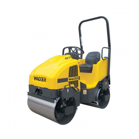
RD 12A Machine Description and Intended Use This machine is a dual drum, ride-on roller. The Wacker Neuson Ride- On Roller consists of an articulated frame onto which is mounted a gasoline or diesel engine, a fuel tank, a hydraulic tank, a water tank, a hydrostatic drive system, two steel drums containing internal eccentric weights, and an operator’s platform with a ROPS (Roll Over Protective... - Page 11 RD 12A Safety Information • Crushing hazards from improper operation (feet, legs, or arms extending outside of the operator work station) and for other persons in the work zone • Line of sight blockage by the ROPS To protect yourself and others, make sure you thoroughly read and understand the safety information presented in this manual before operating the machine.
- Page 12 Safety Information RD 12A 1.2.5 Do not use accessories or attachments that are not recommended by Wacker Neuson. Damage to equipment and injury to the user may result. 1.2.6 Never leave the machine running unattended. 1.2.7 NEVER operate the machine with the fuel cap loose or missing.
-
Page 13: Operator Safety While Using Internal Combustion Engines
RD 12A Safety Information Operator Safety while Using Internal Combustion Engines WARNING Internal combustion engines present special hazards during operation and fueling. Failure to follow the warnings and safety standards could result in severe injury or death. Read and follow the warning instructions in the engine owner’s manual and the safety guidelines below. -
Page 14: Service Safety
Safety Information RD 12A Service Safety A poorly maintained machine can become a safety hazard! In order for the machine to operate safely and properly over a long period of time, periodic maintenance and occasional repairs are necessary. WARNING Personal Protective Equipment (PPE) - Page 15 RD 12A Safety Information 1.4.12 DO NOT open the hydraulic lines or loosen the hydraulic connections while the engine is running! Before dismantling the hydraulic connectors or hoses, ensure that all pressure has been bled from the circuit. Hydraulic fluid under pressure can penetrate the skin, cause burns, blind, or create other personal injury hazards.
-
Page 16: Labels
Labels RD 12A Labels Label Locations wc_si000302gb.fm... -
Page 17: Label Meanings
RD 12A Labels Label Meanings Wacker Neuson machines use international pictorial labels where needed. These labels are described below. WARNING! Read and understand the supplied Operator’s Manual before operating the machine. Failure to do so increases the risk of injury to yourself and others. - Page 18 Labels RD 12A WARNING! Hot surface! WARNING! Hot surface! Hydraulic oil reservoir fill tube. Torque nuts to 13.6-14.7 Nm (120-130 in.lbs.) maximum. CAUTION Lifting point. WARNING! To prevent hearing loss, wear hearing protection when operating this machine. WARNING! Disconnect battery before servicing.
- Page 19 RD 12A Labels Grease points: Inspect and lubricate every 100 hours of operation. WARNING! Avoid crushing area. Articulated steering joint locking location. Lock the articulated steering joint before servicing the machine. Read Repair Manual. Engine will stop without operator seated.
- Page 20 Labels RD 12A CAUTION! Electric shock hazard at auxiliary battery positive terminal. Never touch this terminal and a metal portion of the machine simultaneously. WARNING! Read and understand the supplied Operator’s Manual before operating the machine. Failure to do so increases the risk of injury to yourself and others.
-
Page 21: Lifting And Transporting
RD 12A Lifting and Transporting Lifting and Transporting Lifting the Machine See Graphic: wc_gr003454 Stop the engine. Locking the articulated joint lockarm (a) Before lifting the machine, make sure the articulated joint lockarm is in the LOCKED position. Refer to section Articulation Joint Lockarm for information. -
Page 22: Tying Down And Transporting The Machine
Lifting and Transporting RD 12A Tying Down and Transporting the Machine See Graphic: wc_gr003455 Lock the articulated joint lockarm. Refer to section Articulation Joint Lockarm for information. When transporting the machine, place blocks in front of and behind each drum and use the front and rear tie-down points (a) provided to securely fasten the machine to the trailer (two places). - Page 23 RD 12A Lifting and Transporting Notes: wc_tx001556gb.fm...
-
Page 24: Operation
Operation RD 12A Operation Features and Controls See Graphic: wc_gr002946 Ref. Description Ref. Description Air cleaner Operator’s platform Articulated joint Engine oil filter Hand holds Rear drum fill/drain plug Control panel Rear drum—static Dipstick Scraper bar (4 places) Drain hose—hydraulic tank Sightglass—hydraulic tank... - Page 25 RD 12A Operation 5 13 25 2 wc_gr002946 wc_tx001071gb.fm...
-
Page 26: Control Panel
Operation RD 12A Control Panel See Graphic: wc_gr004114 Ref. Description Ref. Description Hour meter Low fuel indicator Vibration ON indicator Water spray switch - ON and OFF Lights switch - ON and OFF Water spray dial (if equipped) Throttle switch - HIGH and LOW... -
Page 27: Preparing The Machine For First Use
4.3.2 Check the machine and its components for damage. If there is visible damage, do not operate the machine! Contact your Wacker Neuson dealer immediately for assistance. 4.3.3 Take inventory of all items included with the machine and verify that all loose components and fasteners are accounted for. -
Page 28: Roll Over Protection Structure (Rops)
Operation RD 12A Roll Over Protection Structure (ROPS) The machine is equipped with a Roll Over Protection Structure (ROPS). The machine is normally delivered to the customer with the ROPS folded forward to facilitate transport. Do not use the machine without the ROPS in place. The ROPS is designed to protect the operator in a rollover accident. -
Page 29: Foldable Roll Over Protection Structure (Rops) (If Equipped)
RD 12A Operation Foldable Roll Over Protection Structure (ROPS) (if equipped) See Graphic: wc_gr002957 The machine is equipped with a Roll Over Protection Structure (ROPS). The machine is normally delivered to the customer with the ROPS folded forward to facilitate transport. -
Page 30: Rotating Beacon (If Equipped)
Operation RD 12A If the ROPS has been removed from the machine, it must be reinstalled before the machine is used. When reinstalling the ROPS, use the original nuts and bolts and tighten the bolts to the specified torques. Do not weld or drill into the ROPS. Drilling or welding on the ROPS will nullify the ROPS certification. -
Page 31: Lighting Equipment (If Equipped)
RD 12A Operation 4.10 Lighting Equipment (if equipped) See Graphic: wc_gr005892 When working in the dark or in bad visibility, use all the lights available. Replace broken bulbs immediately. Only replace bulbs when the machine is turned off. Remember that your safety and the safety of... -
Page 32: Operator Presence System
Operation RD 12A 4.12 Operator Presence System See Graphic: wc_gr002962 The machine is equipped with an “operator presence system”. This system is part of the driver's seat and senses the weight of an operator in the seat. If the operator is not sitting in the driver's seat, the roller will NOT drive. -
Page 33: Scraper Bars
RD 12A Operation 4.13 Scraper Bars See Graphic: wc_gr003447 Scraper bars, located in front of and behind each drum, are used to prevent dirt and asphalt from sticking to and accumulating on the drum surface. These scrapers are spring loaded. They may be set in the travel position (a) or the scraping position (b) by flipping the bar up or down. -
Page 34: Anti-Vandalism Protection And Machine Access
Operation RD 12A 4.14 Anti-Vandalism Protection and Machine Access Parts of the machine which may be subject to theft or vandalism when the vehicle is parked unattended can be padlocked to prevent unauthorized access or use. Lockable parts are: •... -
Page 35: Articulation Joint Lockarm
RD 12A Operation 4.15 Articulation Joint Lockarm See Graphic: wc_gr002956 A lockarm (23), located below the articulated joint, is provided to secure the front and rear halves of the roller together. Once secured, the lockarm prevents the two halves from swinging together. -
Page 36: Machine Stability
Operation RD 12A 4.16 Machine Stability WARNING Crushing hazards. Certain job site conditions or operating practices may adversely affect machine stability. Follow the instructions below to reduce the risk of tipping or falling incidents. Surface conditions Pay attention to changing surface conditions while operating the machine. -
Page 37: Before Starting
RD 12A Operation • Reduce travel speed and watch the drum position carefully when operating along the edge of an elevated surface. • Keep as much of the drum on the elevated surface as possible. Vibrating on a compacted surface... -
Page 38: Starting
Operation RD 12A • Hydraulic fluid level • Condition of fuel lines • Condition of air cleaner • Operation of the brake system • Fuel level • Water level • Condition of safety belt • Scraper bars—clean and properly adjusted Note: All fluid levels should be checked with the machine on a level surface. - Page 39 RD 12A Operation Note: The ignition switch has an anti-restart feature. If the engine does not start, the switch will need to be turned to the OFF position before it will allow the engine to be cranked again. 4.18.6 Gradually place the choke lever in the OPEN position as the engine warms up.
- Page 40 Operation RD 12A wc_gr002951 wc_tx001071gb.fm...
-
Page 41: Stopping/Parking
RD 12A Operation 4.19 Stopping/Parking See Graphic: wc_gr002953 4.19.1 Stop the machine on a flat surface with a suitable load bearing capacity. 4.19.2 Turn the vibration off by pressing the vibration control button (10) on the forward/reverse lever (15). 4.19.3 Press the water spray switch to the OFF position (61). -
Page 42: Emergency Shutdown Procedure
Operation RD 12A 4.20 Emergency Shutdown Procedure See Graphic: wc_gr001677 Activate the emergency stop switch (63) by pushing the red button in. Pushing the emergency stop switch opens the main circuit breaker and the fuel solenoid, and results in the engine shutting down. The switch will remain activated until the button is pulled out. -
Page 43: Parking Brake
RD 12A Operation 4.21 Parking Brake See Graphic: wc_gr002953 To hold the machine in a stopped position (parked), there is a mechanical parking brake on the rear drive motor. The engine will automatically shut off when the operator leaves the seat, but the parking brake must be set manually. -
Page 44: Parking Brake Adjustment
Operation RD 12A 4.22 Parking Brake Adjustment See Graphic: wc_gr002953 The parking brake is located on the rear drive motor drum support, and is used to prevent the roller from moving when the engine is turned off. Adjust brake for proper holding force as follows: 4.22.1 Unscrew brake lever knob (42) until brake can be applied with... -
Page 45: Direction And Speed
RD 12A Operation 4.23 Direction and Speed See Graphic: wc_gr002953 The forward/reverse control (15) controls both the direction and speed of the roller. Use the control lever, rather than the throttle, to control the speed of the machine while compacting. -
Page 46: Transmission
Operation RD 12A 4.24 Transmission See Graphic: wc_gr002953 Both roller drums are fitted with hydraulic motors which are driven by an infinitely variable displacement pump and hydrostatic transmission. Forward and reverse travel are selected using a forward/reverse control (15) located next to the driver’s seat. In order to comply with... -
Page 47: Vibration
RD 12A Operation 4.25 Vibration See Graphic: wc_gr005893 The vibration is turned ON or OFF by a push button (10) located on the forward/reverse control (15). Press the button to turn vibration ON; press it again to turn it OFF. The vibration ON indicator (50) will light when vibration is on. -
Page 48: Water Spray System
Operation RD 12A 4.26 Water Spray System See Graphic: wc_gr002946, wc_gr003638 Water from the tank is fed to the spray bars by an electric pump. The flow of the water is controlled by a switch and a rotary dial. Press the upper half of the water spray switch (61) to turn the water pump on. -
Page 49: Auxiliary Battery Positive Terminal
RD 12A Operation 4.27 Auxiliary Battery Positive Terminal This machine is equipped with an auxiliary battery positive terminal (45) located on top of the hydraulic tank. CAUTION! Electric shock hazard. Never touch this terminal and a metal portion of the machine simultaneously. -
Page 50: Panel Indicator Lights
Operation RD 12A 4.28 Panel Indicator Lights See Graphic: wc_gr004118 Vibration on indicator (50) This indicator light illuminates to indicate that the vibration is on. Low fuel indicator (56) This indicator light illuminates to indicate that the fuel level is low. -
Page 51: Adding Ballast To Rear Drum
RD 12A Operation 4.29 Adding Ballast to Rear Drum See Graphic: wc_gr002961 The rear drum can be filled with ballast to provide additional weight. Add ballast through plug opening (26). Drum Capacity: 114 liters (30.2 gal.) Added Weight (water ballast): 113 Kg (250 lbs.) If water is used as ballast in areas where temperatures are below freezing, add antifreeze or drain drum after use. -
Page 52: Maintenance
Maintenance RD 12A Maintenance Engine Maintenance Schedule The table below lists basic engine maintenance. Tasks designated with check marks may be performed by the operator. Tasks designated with square bullet points require special training and equipment. Refer to the engine manufacturer’s Operation Manual for additional information. -
Page 53: Roller Maintenance Schedule
RD 12A Maintenance Roller Maintenance Schedule The table below lists basic machine maintenance. Tasks designated with check marks may be performed by the operator. Tasks designated with square bullet points require special training and equipment. Daily Every Every Every 1200 hrs. -
Page 54: Rear Frame Access
Maintenance RD 12A Rear Frame Access See Graphic: wc_gr004333 The operator’s platform is mounted on hinges and can be lifted open to provide access to the water pump, the water filter, the battery, the hydraulic hoses, and the fuel tank. The platform has lifting cylinders that hold the platform in the open position. -
Page 55: Battery
RD 12A Maintenance Battery See Graphic: wc_gr002565 Before servicing this machine, make sure the ingnition switch is in the OFF position and that the battery is disconnected. Attach a “DO NOT START” sign to the machine. This will notify other personnel that the unit is being serviced and will reduce the chance of someone inadvertently trying to start the unit. - Page 56 Maintenance RD 12A Inspect the battery periodically. Keep the battery terminals clean and connections tight. When necessary, tighten the cables and grease the cable clamps with petroleum jelly. Maintain the battery at full charge to improve cold weather starting. NOTICE: Observe the following to prevent serious damage to the machine’s electrical system:...
-
Page 57: Fuel Filter
RD 12A Maintenance Fuel Filter See Graphic: wc_gr000163 5.5.1 Change the in-line fuel filter (a) once a year or every 300 hours of operation. Check the fuel lines and fittings daily for cracks or leaks. Replace as needed. Gasoline is extremely flammable! Turn the engine off and allow the engine to cool before replacing the fuel filter. -
Page 58: Engine Oil And Filter
Maintenance RD 12A Engine Oil and Filter Drain oil while engine is still warm. 5.6.1 Remove oil fill cap (a), drain plug (b), and washer (c) to drain oil. wc_gr007589 Note: In the interests of environmental protection, place a plastic sheet and a container under the machine to collect any liquid which drains off. -
Page 59: Spark Plug
RD 12A Maintenance Spark Plug See Graphic: wc_gr000028 Clean or replace the spark plug as needed to ensure proper operation. Refer to the engine owner’s manual. The exhaust manifold becomes very hot during operation and remains hot for a while after stopping the engine. Do not touch the exhaust manifold while it is hot. -
Page 60: Engine Air Cleaner
Maintenance RD 12A Engine Air Cleaner NEVER use gasoline or other types of low-flash point solvents for cleaning the air cleaner. A fire or explosion could result. WARNING NOTICE: NEVER run the engine without the air cleaner. Severe engine damage will occur. -
Page 61: Grease Fittings
RD 12A Maintenance Grease Fittings See Graphic: wc_gr003457 See section Technical Data for oil quantity and type. Articulation Joint Lockarm: The articulated joint is equipped with grease fittings (a) for lubrication. To avoid being pinched by the machine halves, set the lockarm before... -
Page 62: Hydraulic System Cleanliness
Maintenance RD 12A 5.10 Hydraulic System Cleanliness Keeping the hydraulic oil clean is a vital factor affecting the service life of hydraulic components. Oil in hydraulic systems is used not only to transfer power, but also to lubricate the hydraulic components used in the system. -
Page 63: Hydraulic Oil Requirements
RD 12A Maintenance 5.11 Hydraulic Oil Requirements Wacker Neuson recommends the use of a good petroleum-based, anti-wear hydraulic oil in the hydraulic system of this equipment. Good anti-wear hydraulic oils contain special additives to reduce oxidation, prevent foaming, and provide for good water separation. -
Page 64: Hydraulic Oil Level
Maintenance RD 12A 5.12 Hydraulic Oil Level See Graphic: wc_gr005894 A hydraulic oil level sightglass (29) is located on the side of the hydraulic fluid reservoir. While the machine is turned off, check that the hydraulic oil level is visible at the middle level or higher in the sightglass. If it is not, add oil through the filler port (20) inside the engine compartment. -
Page 65: Changing The Hydraulic Oil & Filter
RD 12A Maintenance 5.14 Changing the Hydraulic Oil & Filter All oils eventually shear or thin out with use, reducing their lubricating ability. In addition, heat, oxidation, and contamination may cause the formation of sludge, gum, or varnish in the system. For these reasons, it is important to change the hydraulic oil at specified intervals. - Page 66 Maintenance RD 12A • Drain the fuel tank and drain the water tank. If ballast was added to the rear drum, also drain the rear drum. • Change the engine oil. • Remove the spark plugs and pour approximately 3 ml (1 ounce) of SAE 30W oil into each engine cylinder through the spark plug opening.
-
Page 67: Towing Bypass Valve
RD 12A Maintenance 5.17 Towing Bypass Valve See Graphic: wc_gr002960 The drive circuit is equipped with a towing valve (43) to allow oil to bypass the drive motors and let the roller freewheel for towing. The towing valve should be used in emergency cases where the machine has become bogged down in loose or muddy soil, or cannot be driven due to an engine or hydraulic system failure. -
Page 68: Towing
Maintenance RD 12A 5.18 Towing Improper hookup and towing is hazardous and could result in injury or death to yourself or others. The towing connection must be rigid, or towing must be done by two WARNING machines of the same size or larger than the towed machine. Connect a machine on each end of the towed machine. - Page 69 RD 12A Maintenance Attach the towing device and machine before you release the brakes. If the engine is running, the machine can be towed for a short distance under certain conditions. The power train and steering system must be operable.
-
Page 70: Basic Troubleshooting
Basic Troubleshooting RD 12A Basic Troubleshooting Problem / Symptom Reason / Remedy ENGINE DOES NOT • Fuel tank empty. START • Wrong type of fuel. • Old fuel. Drain tank, change fuel filter and fill with fresh fuel. • Fuel system not primed. -
Page 71: Schematics
RD 12A Schematics Schematics Electrical Schematic PACKARD WEATHERPACK PACKARD WEATHERPACK PACKARD WEATHERPACK 2 PIN PACKARD WEATHERPACK 2 PIN OPTIONAL OPTIONAL 1201 0973 1201 0973 1201 5792 1201 5792 #202 RED (14 AWG) #202 RED (14 AWG) 165478 165478 #203 GREEN (14 AWG) -
Page 72: Electrical Schematic Components
Schematics RD 12A Electrical Schematic Components Ref. Description Ref. Description Work light switch Rear light (optional) Throttle switch Left head light (optional) Pump switch Right head light (optional) Key switch To magneto kill Vibration indicator light (green) Crank relay Low fuel indicator light (amber) -
Page 73: Hydraulic Schematic
RD 12A Schematics Hydraulic Schematic Hydraulic Schematic Components Ref. Description Ref. Description Steering cylinder Return filter Steering unit Tank Drive motor Suction strainer Bypass lever Vibration solenoid valve Charge pump Exciter motor Main pump Pressure relief valve Exciter pump wc_tx001559gb.fm... - Page 74 Schematics RD 12A Notes...
-
Page 75: Technical Data
RD 12A Technical Data Technical Data Engine Engine Power Rating Net power rating per SAE J1349. Actual power output may vary due to conditions of specific use. Item no. RD 12A Engine Engine type 4-stroke, 2 cylinder, air cooled Engine make... -
Page 76: Roller
Technical Data RD 12A Roller Item No. RD 12A Roller Dry Weight kg (lb.) 985 (2171) Curb Clearance: Right mm (in.) 399 (15.7) Left 208 (8.2) Water Tank Capacity l (gal.) 100 (26.4) Outside Turning Radius m (ft.) 2.45 (8.0) Forward / Reverse km/hr. -
Page 77: Dimensions
RD 12A Technical Data Dimensions mm (in.) 2300 (90.6) (22) 1265 (49.8) (35.4) 1035 1824 (40.8) (71.8) Sound Measurements The operating sound level is: • the sound pressure level at operator’s location (L 85.6 dB(A) wc_td000411gb.fm... -
Page 78: Vibration Measurements
Technical Data RD 12A Vibration Measurements The operator of this machine should expect to be exposed to vibration levels listed below when using the machine in performance of its normally intended function: • Maximum hand/arm vibration levels are: 1.4 m/s (4.6 ft/s... - Page 79 KE40246P2 6/9/05 3:16 PM Page i SAFETY ALERT SYMBOL This Safety Alert Symbol means ATTENTION is involved! Why is SAFETY important to YOU? 3 BIG REASONS : The Safety Alert Symbol identifies important safety messages on machines, safety signs, in manuals, or •...
- Page 80 WORD OF EXPLANATION................FOREWORD......................A WORD TO THE USER ..................FOLLOW A SAFETY PROGRAM ..............PREPARE FOR SAFE OPERATION..............START SAFELY....................WORK SAFELY ....................PARK & SHUTDOWN SAFELY ..............LOAD & UNLOAD MACHINE SAFELY ............TRANSPORTING SAFELY ................PERFORM MAINTENANCE SAFELY ............SPECIAL OPERATING AND MAINTENANCE PRECAUTIONS....
-
Page 81: Word Of Explanation
WORD OF EXPLANATION This Safety Manual covers many different types of Manufacturers produce machines with many roller compactors … including steel wheel rollers, built-in safety features. Employers provide vibratory rollers, rubber-tired rollers, segmented accident prevention programs.Yet, the ultimate pad/sheepsfoot soil compactors and landfill responsibility to operate and maintain your compactors.These may be either self-propelled machine with the skill, care and knowledge... -
Page 82: A Word To The User
A WORD TO THE USER It is your responsibility to read and understand this safety manual and the manufacturer's manual(s) before operating your machine.This safety manual takes you step-by-step through your working day. Remember that YOU are the key to safety. Good safety practices not only protect you but also protect the people around you. - Page 83 FOLLOW A SAFETY PROGRAM KNOW WHAT IT IS? Consult your supervisor for specific instructions on a job, and the personal safety equipment required. For instance, you may need: • Hard Hat • Safety Shoes • Eye Protection • Face Protection •...
- Page 84 PREPARE FOR SAFE OPERATION LEARN TO BE SAFE NEVER operate a machine which is new to you without first being instructed in its proper operation. READ the operator’s manual. If one has not been provided, GET ONE AND STUDY IT BEFORE CHECK IT OUT! OPERATING THE MACHINE.
- Page 85 PREPARE FOR SAFE OPERATION FIRE PREVENTION Because ether or other starting fluids are flammable, do not smoke when using them. Always follow the Never allow flammable fluids or materials to instructions on the container and in the operator’s contact hot surfaces. manual for your machine.
- Page 86 PREPARE FOR SAFE OPERATION Before starting, carefully inspect your machine for A stalled or faltering engine can result in a real any evidence of physical damage such as cracking, hazard when operating on grades, in traffic or in bending or deformation of plates or welds. Check for heavily congested areas.
- Page 87 START SAFELY Walk around your machine once more just prior to mounting it – checking for people and objects that might be in the way – then MOUNT PROPERLY USING STEPS AND HANDHOLDS PROVIDED. Always use seat belts if your machine is equipped with a ROPS.
-
Page 88: Work Safely
START SAFELY COLD WEATHER OPERATION BOOSTER CABLE INSTRUCTIONS Consult the engine manufacturer’s operation manual 1. Connect positive (+) cable to positive post of for proper cold weather starting procedure. discharged battery. When using cold weather starting aids, be sure to 2. - Page 89 WORK SAFELY For maximum safety on machines with more than one operator’s position, operate from the position giving the greatest visibility of potential hazards. NEVER allow unqualified or unauthorized personnel to operate your machine. NEVER allow other personnel to ride on your machine unless appropriate seating is provided …...
- Page 90 WORK SAFELY Avoid operating your machine too close to an overhang, deep ditch or hole. If your machine inadvertently gets close to a tipping condition or drop-off, STOP and get off the machine after applying the parking brake … plan your moves carefully before proceeding.
- Page 91 PARK AND SHUT DOWN SAFELY PARK SAFELY angles to the slope. Make sure the machine is on a firm footing, and that there is no danger of sliding. Park in an off the road area, out of traffic, or as Do NOT leave your machine until you are sure it is instructed.
- Page 92 LOAD AND UNLOAD MACHINE SAFELY Loading and unloading machines always involves • The ramp surface must provide adequate traction. potential hazards. EXTREME CAUTION SHOULD Be sure the surface is clean and free of grease, oil, ice, and loose material. BE USED. •...
- Page 93 TRANSPORTING SAFELY TOWING NEVER allow anyone to ride on a trailer or towed machine. (FIG. 28) ALWAYS use EXTRA care when towing a trailer or machine… when maneuvering in tight places, when backing When necessary to disconnect and park a trailer or (visibility is reduced, and jackknifing must be avoided), and towed machine, ALWAYS select a location that is level when towing on steep grades.
- Page 94 PERFORM MAINTENANCE SAFELY CLOTHING AND PERSONAL machinery. (FIG. 31) Heavy gloves should be worn PROTECTIVE ITEMS for many operations. Keep hands and clothing well away from engine EXHAUST FUMES fan and moving parts while engine is running. Engine exhaust fumes can cause sickness or death. ALWAYS wear appropriate safety glasses, goggles If it is necessary to run an engine in an enclosed or face shield when working.
- Page 95 PERFORM MAINTENANCE SAFELY Before beginning welding or burning operations, drain JACKING AND BLOCKING fuel lines and tank and move all flammable material to a ALWAYS lower all movable attachments to the ground safe distance, and be certain a fire extinguisher is readily or to their lowest position before servicing a machine.
- Page 96 PERFORM MAINTENANCE SAFELY FIRE PREVENTION CHECKLIST (FIG. 36) • Remove debris such as rags, coal dust, oil, leaves, pine needles. • Check and repair fuel and hydraulic leaks. • Check and repair damaged wiring. • Prevent hose and electrical wire harness abrasion.
- Page 97 PERFORM MAINTENANCE SAFELY SERVICING COOLING SYSTEM When checking coolant level: • Stop the engine and let the engine and radiator cool before checking. (FIG. 38) If an overheated engine requires a shutdown: • Wait for the radiator to cool. The hot pressurized coolant can cause burn injuries.
- Page 98 PERFORM MAINTENANCE SAFELY BATTERY SERVICING To prevent a battery explosion: (Fig. 40) • Maintain the electrolyte at the recommended level. Check level frequently. Add distilled water to batteries only before starting up, never when shutting down.With electrolyte at the proper level, less space is available for gases to accumulate in the battery.
- Page 99 PERFORM MAINTENANCE SAFELY HYDRAULIC SYSTEMS (CONT’D) Keep hydraulic relief valve settings set to the manufacturer’s recommendations. Excessive If you are struck by escaping hydraulic fluid pressures could result in structural or under pressure, serious injury can occur if hydraulic failures. Low pressure could result in proper medical treatment is not administered loss of control.
- Page 100 PERFORM MAINTENANCE SAFELY TIRE PRESSURE Check tire pressure before starting operation. An air pressure rise during operation is normal and should NOT be reduced. Overloads or over- speeds may produce increased tire pressures due to heat. Never bleed tires. Reduce your load – or speed –...
- Page 101 SPECIAL OPERATING AND MAINTENANCE PRECAUTIONS PARKING AND TRANSPORTING Extreme care should be exercised when loading or unloading a walk-behind roller. It is generally ALWAYS select a level area to park in and, if best to stand behind and to one side rather than possible, one where children are unlikely to be directly behind a machine being propelled up or present.
- Page 102 SPECIAL OPERATING AND MAINTENANCE PRECAUTIONS FOR LANDFILL COMPACTORS General Operators of landfill compactors should carefully handle fill materials that could be picked up and thrown by the wheels, become lodged in the machine, or that are highly flammable. Frequent checks should be made for wire, cable or other material wound around the axle members.
-
Page 103: Test Your Knowledge
TEST YOUR KNOWLEDGE Do you understand this AEM SAFETY MANUAL AND • Proper operating procedures? ITEMS SUCH AS … • Proper parking, shutdown, and dismounting procedures? • Your safety program? • Proper maintenance procedures? • Your machine manufacturer’s manual(s)? • Proper loading and unloading procedures for •... - Page 104 KE40246P1 6/9/05 3:14 PM Page 1...
- Page 106 Fax: +49 - (0)89-3 54 02-390 Wacker Neuson Corporation · N92W15000 Anthony Ave. · Menomonee Falls, WI 53051 · Tel. : (262) 255-0500 · Fax: (262) 255-0550 ·Tel. : (800) 770-0957 Wacker Neuson Limited - Room 1701–03 & 1717–20, 17/F. Tower 1, Grand Century Place, 193 Prince Edward Road West, Mongkok, Kowloon, Hongkong.
Need help?
Do you have a question about the RD 12A and is the answer not in the manual?
Questions and answers