Table of Contents
Advertisement
I
N
S
T
R
U
C
T
I
O
N
M
A
N
U
A
L
M
T
M
T
ODELING
HE
ODELING
HE
C
JN-4D J
C
JN-4D J
URTISS
ENNY
URTISS
ENNY
1917
1917
!
!
!
!
PREPARED BY BEN LANKFORD
Technical Characteristics
SCALE: 3/4" = 1' 0" (1:16)
WINGSPAN: 32-1/2" (826 mm)
FUSELAGE LENGTH: 20-1/2" (521 mm)
Manufactured by Model Airways
A Division of Model Expo, Inc., Hollywood, FL
http://www.modelexpo-online.com
Model Airways Kit No. MA1010
Advertisement
Table of Contents

Related Manuals for Model Airways CURTISS JN-4D JENNY


Summary of Contents for Model Airways CURTISS JN-4D JENNY
- Page 1 1917 PREPARED BY BEN LANKFORD Technical Characteristics SCALE: 3/4" = 1' 0" (1:16) WINGSPAN: 32-1/2" (826 mm) FUSELAGE LENGTH: 20-1/2" (521 mm) Manufactured by Model Airways A Division of Model Expo, Inc., Hollywood, FL http://www.modelexpo-online.com Model Airways Kit No. MA1010...
-
Page 2: History
HISTORY Jenny biplane was introduced in 1916 and manufactured by aircraft used a wheel for controlling the rudder, but the D model Jenny’s the Curtiss Aeroplane and Motor Corporation in Hammondsport, used sticks. Quite a few have been restored and are still Jenny New York. -
Page 3: Table Of Contents
5. Mounting the Vertical Stabilizer...........16 Bibliography ................38 Stage 3: Building the Basic Fuselage ......16 Photos of Model Airways’ Jenny ........39 1. Building the Fuselage Jig............16 2. Building the Sides of the Fuselage........17 3. Placing the Sides in the Building Jig........17 4. -
Page 4: Introduction And Credits
Model Airways may not Ken answered many questions that had me puzzled while devel- represent any one particular aircraft. Most modifications oping the kit design. -
Page 5: Before You Begin
G. Glue packaging parts list. Each of these have been double scale, and designated 2X (1-1/2" = assigned a Model Expo (Model Airways) WP 1'0"). Most dimensions can be lifted directly stock part number. These parts must be cut off the plans by using draftsman dividers or White glue, Carpenter’s wood glue (yel-... -
Page 6: Kit Lumber
However, it is recommended that what, you could accidentally glue the protec- another. Model Airways supplies enough you stain the wood parts and seal the britan- tive sheet to the model parts, or even to the extra wood to complete the model before nia castings for protection. -
Page 7: Stage 1: Building The Wings
STAGE 1: BUILDING THE WINGS Plan Sheet 2 shows all the details for con- Front beam web between first two ribs shown on the plan. These stiffeners prevent structing the wings, wing struts, and rigging inboard and center section – 3/32" x rib cracking on the real aircraft. -
Page 8: Installing The Wing Ribs
Since the wing ribs have undercamber, jig FIG. 1-2 WING RIB JIG SETUP shims are required to correctly locate the beam flanges at their proper angles. The shims are laser-cut parts. TYPICAL WING RIB The leading edge is a rectangular spar and is 3/32"... -
Page 9: Installing The Wing Tips, Trailing Edge, And Upper Beam Flanges
The web blocks to be described in Option: FIG. 1-5 WEB BLOCKS AT COMPRESSION RIBS the next paragraph can be glued to the beam WING RIB W4 OR W6 webs before the beam webs are glued between the ribs. At each compression Installing web blocks: rib, add the web blocks on each side of the ribs. -
Page 10: Adding Miscellaneous Stiffeners And Lower Wing Walk
ommended). Fit the stringers in the precut FIG. 1-8 WING TRAILING EDGE notches in the ribs. Fix with glue. The stringers are rather delicate, so be careful handling the strips. Out at the wing tips the stringers angle toward the wing tip strip as seen in Figure 1-7 You should be able to slide the lower strip... -
Page 11: Installing Wing Strut, Kingpost, And Wing Skid Support Pads And Fittings
10.Installing Wing Strut, Kingpost, and Wing Skid Support Pads and FIG. 1-13 STRUT SUPPORT PADS & WING WIRE FITTING Fittings PHOTO-ETCHED FITTING W22 – BEND EYES TO WING WIRE ANGLES. CUT OFF EYES NOT NEEDED The support pads are fitted on each side of AT A GIVEN LOCATION. -
Page 12: Installing The Drag Wires
of the wings (Figure 1-16 and plan Detail 2- FIG. 1-16 AILERON CONTROL CABLE SHEAVES . Actual rigging of the aileron control wires CASTING C3 will be discussed in a later stage. CASTING C4 On the right side of the upper wing center sec- BRASS ROD tion add a similar U pin that will serve as a fair- FITTING AT TOP AND... -
Page 13: Building The Upper Wing Center Section
are at the lower end at the wing and at top of FIG. 1-19 WING SKIDS the kingpost for the fore and aft wires. LEADING EDGE The kingposts are perpendicular to hori- Note: zontal and not at an angle like the wing struts. SUPPORT PADS UNDERSIDE 17. -
Page 14: Stage 2: Building Vertical And Horizontal Stabilizers, Rudder, And Elevator
STAGE 2: BUILDING VERTICAL & HORIZONTAL STABILIZERS, RUDDER, & ELEVATOR Plan Sheet 4 provides all the details for FIG. 2-1 VERTICAL STABILIZER ASSEMBLY constructing the tail surfaces. The plan also BRACE WIRE FITTINGS R1 shows the landing gear, but this will be dis- LOCATE THIS STIFFENER ON CENTERLINE cussed in a later stage. -
Page 15: Building The Horizontal Stabilizer
joint that intersects with the steel rod. FIG. 2-3 HORIZONTAL STABILIZER ASSEMBLY On the third rib from the top, add the two filler COPPER TAPE AT RIBS AND STIFFENERS CENTERLINE blocks above and below the rib at the leading .020" X 1/16" CAP STRIPS BOLTING BLOCK edge. -
Page 16: Mounting The Vertical Stabilizer
top and bottom of the ribs like the stringers hinges in the leading edge, then assemble stabilizer is bolted on. of the wing ribs. These notches are not the elevator to the horizontal stabilizer using You can install the brace wires at this time laser-cut into the elevator ribs for fear the brass strip as fake hinges. -
Page 17: Building The Sides Of The Fuselage
(F27 through F32) and glue. These dowels FIG. 3-4 COMPLETED FUSELAGE SIDE are used for rubber banding the fuselage sides to the formers. Fit each former in the slots in the center piece. Check with a square to see if they are LONGERONS perpendicular to the center piece and board. -
Page 18: Longeron Splices
the front seat back. At the bottom of the tion 11, which is the same as the longerons). (F15) from top to bottom longerons. The 5. Longeron Splices fuselage the struts are 3/16" square. This is front nose plate is also a photo-etched copper strictly a model item. -
Page 19: Installing The Cockpit Floor Board Supports And Floor Boards
bearers are parallel to each other, so posi- FIG. 3-11 INSTALLING NOSE & NOSE SIDE PLATES tion them thus. Glue the bearers at both ends. On the real aircraft the engine bearers are held to the support beam by U bolts over BEND THESE TABS DOWN the bearers. -
Page 20: Installing The Fuselage Strut Clips
for the copper fake tubing to be added later. FIG. 3-14 INSTALLING SEAT RAILS Glue the panel on top of the longerons just aft of the Station 4 horizontal strut in the loca- tion shown on the plan. Add a small chock at 1/16"... -
Page 21: Installing Cross Brace Wires
through illustrate the Figures 3-18 3-20 FIG. 3-17 CLIPS AT STATIONS 6 TO 11 FIG. 3-18 CLIPS AT STATION 2 strut clips at Stations 2 through 5. The side brace wires from Stations 1 to 5 are BEND TAB OVER double on the real aircraft, side to side. -
Page 22: And Additional Rigging
STAGE 4: INSTALLING COCKPIT CONTROLS AND SEATS, AND ADDITIONAL RIGGING Throttles: Install a throttle (E8) in both and leave it in the fuselage. You can attach it to Plan Sheet 5 illustrates all the details for cockpits on the right longeron. While you the rudder control horns later installing cockpit controls. -
Page 23: Building And Installing The Seat Supports, Seats, And Rail Cross Strut
FIG. 4-4 JOYSTICK ASSEMBLY FIG. 4-5 ELEVATOR BAR ASSEMBLY TURNBUCKLE R3A CONNECTING LINK C7D STATION 6 SEE FIG. 4-5 COIL ENOUGH LINE FOR HOOKUP LATER CONNEC- CONNECTING TION TO LINK C7C ELEVATOR JOYSTICKS SHAFT CASTING C9 END CASTING C11 AILERON CONTROL QUADRANT C8 CUT THIS... -
Page 24: Radiator, Fuel Tank,And Prop, And Final Rigging Of Cross Brace Wires
STAGE 5: BUILDING AND INSTALLING THE OX-5 ENGINE, RADIATOR, FUEL TANK, AND PROP , AND FINAL RIGGING OF CROSS BRACE WIRES Plan Sheet 5 covers all the details for the FIG. 5-1 FUEL TANK ASSEMBLY engine and engine component installation. A propeller detail is also shown on Sheet 5. -
Page 25: Building The Ox-5 Engine
The fuel tank is supported by two brass FIG. 5-3 BLOCK ASSEMBLY straps, one end hanging off the rear ends of the engine bearers and the other ends hang- ing on the top horizontal strut at Station 4. This is just one method of supporting the UPPER BLOCK E15A tank. - Page 26 you drilled on each side of the rear face of FIG. 5-5 V INTAKE MANIFOLD & CARBURETOR the lower engine block. Drill a hole into the carburetor filter for the fuel line wire, and add the fitting and hole HOLES DRILLED IN for the throttle arm wire coming from the BACK OF BLOCK cockpit.
- Page 27 one or more of the pipes or manifolds to FIG. 5-9 WATER INLET PIPING hold the alignment, then glue the four cylinders at once. Anyway you choose will be acceptable. The important issue is that all these parts fit together properly. Adjust- E32 LONG (RIGHT SIDE) ments would be difficult with a cylinder out...
-
Page 28: Installing The Engine And Radiator
of the manifolds. This pin is for the flex air FIG. 5-12 INSTALLING EXHAUST MANIFOLDS heater tubing between the exhaust manifold and carburetor. Since the manifold casting is identical for both sides, cut the top pin off REAR LEFT CYLINDER each casting. -
Page 29: Installing Engine Piping, Tubing, And Control Linkages
attach to the upper fuselage strut fittings at FIG. 5-16 OIL & WATER LINES TO COCKPIT GAUGES Station 2 and are secured at the clips molded into the sides of the radiator. Cut a rabbet in OIL PRESSURE GAUGE WATER the end of the strut to accept the clip on the TEMPERATURE OIL PRESSURE GAUGE... -
Page 30: Rigging Final Fuselage Cross Brace Wires
6. Building and Installing the Prop sides of the water pump and the lower on the plans. Before carving the shape of the holes you drilled in the sides of the V intake prop, mark the leading and trailing edges, The prop shown on the plans is patterned manifold. -
Page 31: Building And Installing The Landing Gear
a protective metal strip for the wooden skid. FIG. 6-2 LANDING GEAR STRUTS Fit the support fitting in the fuselage, gluing CASTING (or pinning) the upper end under the fuse- CASTING FITTING R1 ON INSIDE OF STRUTS L7L (LEFT) L8L (LEFT) lage Station 11 upper horizontal strut, and FOR CROSS BRACE WIRES L7R (RIGHT) - Page 32 to hold the gear rigid. The turnbuckles for FIG. 6-5 INSTALLING GEAR PLATES FIG. 6-6 AXLE INSTALLATION the landing gear are the long ones, R3B, and are located at the fuselage end. Refer to Plan Sheet 6 for wire details. Completing the details (Figure 6-5): FRONT STRUT REAR STRUT...
-
Page 33: Stage 7: Installing The Cockpit Cowl, Wings
STAGE 7: INSTALLING THE COCKPIT COWL, WINGS, STABILIZERS, RUDDER, AND ELEVATOR, AND COMPLETING THE RIGGING Plan Sheet 6 shows the aileron, rudder, and FIG. 7-1 INSTALLING THE COCKPIT COWL elevator control line rigging, and the struc- tural rigging. In addition, refer to Sheet 3 for FORMING THE COWL COPPER TAPE –... -
Page 34: Rigging The Rudder And Elevator Control Wires
Installing the horizontal stabilizer (Figure FIG. 7-3 INSTALLING HORIZONTAL STABILIZER Set the horizontal stabilizer, which 7-3): already has the vertical stabilizer and elevators TRAILING EDGE attached, to top of the fuselage at the tail. Block up each end of the horizontal stabilizer so it’s SPAR EYE BOLT (BOTH SIDES) an equal distance above the building board on... -
Page 35: Installing The Lower Wings
this point, so it is best to install the fore and aft FIG. 7-6 INSTALLING THE UPPER WING CENTER SECTION brace wires. The had several arrange- Jenny ments for the strut wiring. The one we select- COMPLETED CENTER SECTION ed is most common. First, rig the forward cross wires from the top of the struts across W22 FITTINGS UNDER the fuselage to the R1 fitting on the inside top... -
Page 36: Rigging The Interplane Strut Cross Brace Wires, Flying Wires, Landing Wires, Drag Wires, And Kingpost Wires
FIG. 7-10 INTERPLANE STRUT FIG. 7-11 FLYING & LANDING WIRES BRACE WIRES LANDING WIRE – PASS FLYING WIRES BETWEEN FLYING WIRES SINGLE LANDING WIRES W22 ON CENTER SECTION TWO R1 EYES DOUBLE DOUBLE FLYING WIRES FLYING WIRES .010" .010" GRAY CORD GRAY R3B LONG NYLON... -
Page 37: Rigging The Aileron Control Wires
structed the upper wing, do it now. With the lage and are in a straight line. You don’t want wing rigging completed, you can remove the any sweep back or up with the wings. When support blocks under the lower wings, or all is correct and secured to the blocks, glue leave them in place for now in the fuselage the fake hinge pins in the fuselage. -
Page 38: Bibliography
BIBLIOGRAPHY Resurrection of a Jenny WWI Aero: The Journal of the Early Jenny Was No Lady: The Story of the by Chester Peek. Airplane JN-4D Three Peaks Publishing, Norman, OK, 1995. A quarterly journal published by Jack R. Lincke. W.W. Norton by Leonard E. -
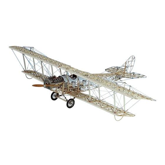
Page 39: Photos Of Model Airways' Jenny
PHOTOS OF MODEL AIRWAYS’ JENNY... - Page 40 OTHER FINE KITS FROM MODEL AIRWAYS 1:16 Scale Open Framework Laser-Cut Wood and Metal Kits Detailed wood, Britannia metal, copper, aluminum, steel, and rubber parts mean uncompromising quality. NIEUPORT 28, 1917 Model Airways Kit No. MA1002 Open framework kits show the intricacies of construction.
Need help?
Do you have a question about the CURTISS JN-4D JENNY and is the answer not in the manual?
Questions and answers