Table of Contents
Advertisement
INSTRUCTION MANUAL
M
T
M
T
ODELING
HE
ODELING
HE
S
C
F.1
S
C
F.1
OPWITH
AMEL
OPWITH
AMEL
, 1917
W
W
I B
F
A
, 1917
W
W
I B
F
A
CRAFT
ORLD
AR
RITISH
IGHTER
IR
!
CRAFT
ORLD
AR
RITISH
IGHTER
IR
!
!
!
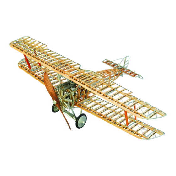
Technical Characteristics
Scale: 3/4" = 1' (1:16)
Wingspan: 21" (534 mm)
Fuselage Length : 14-1/16""
(584.2 mm)
Instructions and prototype by Kenneth H. Goldman
Manufactured by Model Shipways, Inc. dba Model Expo • Hollywood, Florida
Sold by Model Expo, a division of Model Shipways, Inc.
http://www.modelexpo-online.com
Model Airways Kit No. MA1030
Advertisement
Table of Contents

Subscribe to Our Youtube Channel
Related Manuals for Model Airways SOPWITH CAMEL F.1


Summary of Contents for Model Airways SOPWITH CAMEL F.1
- Page 1 Fuselage Length : 14-1/16"" (584.2 mm) Instructions and prototype by Kenneth H. Goldman Manufactured by Model Shipways, Inc. dba Model Expo • Hollywood, Florida Sold by Model Expo, a division of Model Shipways, Inc. http://www.modelexpo-online.com Model Airways Kit No. MA1030...
-
Page 2: Table Of Contents
Italian were developed by Luigi Volonté. The text was rewritten in English and expanded by Kenneth H. Gold- man, who also built the model. Copyright 2006 by Model Airways, Inc., a division of Model Shipways, Inc., dba Model Expo • Hollywood, Florida INDEX INDEX Stage 4: Building The Fuselage......13-15... -
Page 3: Before You Begin
E. Miscellaneous Before You Begin Parts 1. Tweezers (a few) 2. Small fine pointed scissors A parts list is included in each of the construc- The SOPWITH CAMEL kit is intended as a 3. Miniature pliers tion stages, noting the parts required for that structural, non-flying, model without any fab- particular stage. -
Page 4: Painting & Staining The Model
intricacy of the finished model, this is best tings, such as turnbuckles and instruments Getting Started done as you go. Using carpenter’s glue on castings, can be painted black. Varying the raw wood allows the strongest bond, but tones on the various parts will add a nice Before commencing each stage of construc- inevitable glue smears and runs leave the contrast to the finished model. - Page 5 Slip the induction box (CLE-07) onto the Glue the igniter ring (CLE-08) to the induc- Complete the engine group by attaching the brass tube at the rear of the engine. Referring tion box so that the holes line up between ignition wires (WP1218) from the igniter to Engine Photograph 2, holding an induc- each pair of cylinders and the small gear faces...
-
Page 7: Stage 2: Building The Wings
Propeller group: Referring to Fig.05, laminate the propeller layers (CLE17). Take care to stack the layers in the correct order. When viewed from the front in a vertical position, the stack goes from longest to shortest with the shortest layer closest to you. Curved edges would then be upper left and lower right. - Page 8 Parts List For Stage 2 (continued) Rib Pins WP3671 Leading edges 5/32" x 3/16" basswood strips WP3648 Front spars 5/32" x 5/32" basswood strips WP3631 Rear spars 1/8" x 1/8" basswood strips WP3625 Front aileron spars 3/32" x 3/32" basswood strips WP3618 Rear aileron spars 1/16"...
- Page 9 glue. The procedure basically is the same ailerons – Plan 03. Finish off the trailing horns angle forward and are placed atop the for the lower wing, except each half is edge by wrapping the joints with 1/2" upper wing and below the bottom wing. rigged separately.
-
Page 12: Stage 3: Building The Empennage
STAGE 3: BUILDING THE EMPENNAGE Parts List For Stage 3 CAW09 Horizontal stabilizer ribs 8 laser-cut plywood CAW10 Stabilizer nose ribs 6 laser-cut plywood CAW32 Elevator and rudder hinges 7 Britannia castings CAW33 Horizontal stabilizer rim 1 Britannia casting CAW34 Elevator 1 Britannia casting CAW35... -
Page 13: Stage 4: Building The Fuselage
STAGE 4: BUILDING THE FUSELAGE Although it is possible to construct the fuselage atop the full-size you lay out the vertical frame members for one side along the left plans, as you did with the wings, several construction jigs are depict- edge of the vertical frames in the drawing make sure you do the ed on plan sheet 05 to facilitate assembly. -
Page 16: Stage 5: Building The Engine Mount
STAGE 5: BUILDING THE ENGINE MOUNT AND PLUMBING Preparation: Parts List For Stage 5 Cut two 1" lengths of WP129K-1.5 to CAF38 Engine Mount Britannia casting make the air intake tubes, then file a 106º CAF39 Oil pump Britannia casting angle to one end of each tube. -
Page 17: Stage 6: Building The Cockpit & Controls
STAGE 6: BUILDING THE COCKPIT AND CONTROLS Parts List For Stage 6 CAF16 Rear machine gun support 1 Britannia casting CAF53 Pulsometer 1 Britannia casting CAF17a&b Oil tank 2 Britannia castings CAF54 Magneto switches 2 Britannia castings CAF18 Main fuel tank 2 Britannia castings CAF56 Clock... - Page 18 * Note that Fig.F10 is a schematic that does the longerons, behind CAF21. Refer to Fig.25. not purport to show the actual piping runs. Use the provided copper wire to pipe both Insert the tail skid (CAF64) into the socket The runs should be kept as short as possible fuel tanks to the fuel tank selector (CAF34) at the tail and, using the gray twine...
-
Page 19: Stage 7: Epennage Installation & Cabling
STAGE 7: EPENNAGE INSTALLATION AND CABLING Empennage assembly: Parts List For Stage 5 Center the horizontal stabilizer on the fuse- W042 Turnbuckles Britannia castings lage top by positioning the spar at Frame WP1205 Rigging and control cables Metal-gray thread “I.” It is recommended that you strengthen the joint by drilling through the spar and WP2839 Cable crimps... -
Page 20: Stage 8: Attaching The Lower Wing
STAGE 8: ATTACHING THE LOWER WING AND UNDERCARRIAGE Tie off the ailerons to avoid damaging them Parts List For Stage 8 and glue the lower wing into the slots under the fuselage. There should be a space CAF69 Axle 1 each Britannia casting forward of the front spar through which the CAF70 L/R... -
Page 23: Stage 9: Attaching The Upper Wing
STAGE 9: ATTACHING THE UPPER WING, CABLING AND BRACING Cabane struts and preparation: Parts List For Stage 9 The tops of the rear undercarriage brackets CAW40 Cabane struts (4 numbered) 1 ea. Britannia castings should protrude slightly above ribs CAW03 CAW41 False bolts Britannia castings... - Page 24 Lower Wings...
- Page 25 Wing Tip...
-
Page 26: Stage 10: Finishing Touches
STAGE 10: FINISHING TOUCHES Cockpit coaming: Parts List For Stage 10 Form the cockpit coaming (CAF59) from A011 Outer wheel halves Britannia castings the provided 14 AWG insulated copper A012 Inner wheel halves Britannia castings wire. The overall shape is roughly the outline of a potato chip. - Page 27 COLOR PHOTOS CAN BE VIEWED ON OUR WEBSITE - WWW.MODELEXPO-ONLINE.COM...
-
Page 28: More Great Model Airways Kits
Scale 1:16 (3/4" = 1 ft.) Buy direct from our website www.modelexpo-online.com for current prices and other great Model Airways, Model Shipways and Guns of History kits. We also carry Guillow’s balsa airplane kits, hobby tools, books, glues, paints, & much more!
Need help?
Do you have a question about the SOPWITH CAMEL F.1 and is the answer not in the manual?
Questions and answers