Table of Contents
Advertisement
Quick Links
SERVICE MANUAL
COMPACT COMPONENT SYSTEM
STANDBY/ON
SUBWOOFER
SOUND
LEVEL
MODE
ON SCREEN V.INTRO
1
2
3
HIGHLIGHT
SLOW
4
5
6
AUX
7
8
9
FM MODE/
STILL
KEY CONTROL
10
+10
SLEEP
RETURN
KARAOKE
ECHO
FM/AM
TAPE
FADE
TAPE A/B
MUTING
CD
DISC SKIP
SELECT
+
VOLUME
PREV .
NEXT
VOLUME
–
RM–SMXG65VU REMOTE CONTROL
SP-MXG65V
CA-MXG68V
CA-MXG65V
Contents
Safety precautions
Preventing static electricity
Important for laser products
Disassembly method
Wiring connection
Adjustment method
MX-G68V
MX-G65V
STANDBY
STANDBY/ON
PLAY & EXCHANGE
COMPACT
MX-G65V
COMPACT COMPONENT SYSTEM
DIGITAL VIDEO
PHONES
SELECT
CLOCK
/ TIMER
DISPLAY
REPEAT
PROGRAM
RANDOM
REC START
CD
PBC
RETURN
VCD NUMBER
/STOP
REC START
DUBBING
EJECT
A
FULL - LOGIC CONTROL
PLAY
CA-MXG65V
Model
Shanpagne-gold
Silver
1-2
1-3
1-4
1-5
1-18
1-19
COPYRIGHT
2001 VICTOR COMPANY OF JAPAN, LTD.
DISC CHANGE
CD-R / RW PLAYBACK
SOUND
MODE
VIDEO CD
SUBWOOFER
LEVEL
PRESET
NEXT
PREV
SET
CANCEL
/DEMO
TUNING
TAPE A
TAPE B
EJECT
B
CD SYNCHRO RECORDING
REC/PLAY
SP-MXG65V
Color
Flow of functional operation
until TOC read
Maintenance of laser pickup
Replacement of laser pickup
Troubleshooting
Description of major ICs
MX-G68V/MX-G65V
Area Suffix
US
Singapore
Saudi Arabia
UX
VIDEO CD
PlayBack
Control
1-23
1-24
1-24
1-25
1-33~52
No.20995
Jul. 2001
Advertisement
Table of Contents

Related Manuals for JVC MX-G68V


Summary of Contents for JVC MX-G68V
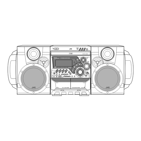
- Page 1 MX-G68V/MX-G65V SERVICE MANUAL COMPACT COMPONENT SYSTEM MX-G68V MX-G65V Area Suffix Singapore Saudi Arabia DISC CHANGE STANDBY STANDBY/ON VIDEO CD CD-R / RW PLAYBACK PLAY & EXCHANGE SOUND MODE VIDEO CD SUBWOOFER LEVEL PRESET NEXT PREV COMPACT MX-G65V COMPACT COMPONENT SYSTEM...
- Page 2 MX-G68V/MX-G65V 1. This design of this product contains special hardware and many circuits and components specially for safety purposes. For continued protection, no changes should be made to the original design unless authorized in writing by the manufacturer. Replacement parts must be identical to those used in the original circuits. Services should be performed by qualified personnel only.
-
Page 3: Preventing Static Electricity
MX-G68V/MX-G65V Preventing static electricity 1. Grounding to prevent damage by static electricity Electrostatic discharge (ESD), which occurs when static electricity stored in the body, fabric, etc. is discharged, can destroy the laser diode in the traverse unit (optical pickup). Take care to prevent this when performing repairs. -
Page 4: Important For Laser Products
MX-G68V/MX-G65V Important for laser products 1.CLASS 1 LASER PRODUCT 5.CAUTION : If safety switches malfunction, the laser is able to function. 2.DANGER : Invisible laser radiation when open and inter 6.CAUTION : Use of controls, adjustments or performance of lock failed or defeated. Avoid direct exposure to beam. -
Page 5: Disassembly Method
MX-G68V/MX-G65V Disassembly method Metal cover <Main body> Removing the metal cover (See Fig.1 and 2) Remove the three screws A attaching the metal cover on the back of the body. Remove the six screws B attaching the metal cover on both sides of the body. - Page 6 MX-G68V/MX-G65V RCW6 UCW3 Front panel assembly FLdispaly & system Rear panel control board Fig.4 Fig.5 Adhesive card wire strap CD changer unit CD changer unit Rear panel Rear panel Fig.6a Fig.6b Front panel assembly Removing the front panel assembly Front panel assembly (See Fig.7 to 9 )
- Page 7 MX-G68V/MX-G65V Front panel assembly Joint b Joint b Main board Bottom side Joint c Fig.8 Removing the heat sink & amplifier Fig.9 board (See Fig.10 to 12) Prior to performing the following procedure, remove the metal cover and the CD changer unit.
- Page 8 MX-G68V/MX-G65V Removing the tuner board (See Fig.11 and 13) Rear panel Prior to performing the following procedure, remove CON01 the metal cover and CD changer unit. Disconnect the card wire from connector CON01 on the tuner board. Main board Remove the two screws L attaching the tuner board.
- Page 9 MX-G68V/MX-G65V Removing the power ICs Heat sink (See Fig.16 and 17) Prior to performing the following procedure, remove the metal cover, CD changer unit, heat sink & amplifier board . Remove the four screws P attaching the power ICs to the heat sink.
- Page 10 MX-G68V/MX-G65V <Front panel assembly> UCW1 Power switch board Prior to performing the following procedure, remove Tab c the metal cover, the CD changer unit and the front panel assembly. Removing the power switch board UCW2 FLdiplay & system control board (See Fig.19)
- Page 11 MX-G68V/MX-G65V <CD changer unit> CD tray Prior to performing the following procedure, remove Loading pulley gear the CD changer unit. Removing the CD tray (See Fig.1 to 3) Disconnect the card wire from connector SW1 of the video CD board.
- Page 12 MX-G68V/MX-G65V Removing the sensor board / the turn table motor assembly (See Fig.6 to 8) Prior to performing the following procedure, remove Tab b the CD tray. Remove the screw A attaching the sensor board and release the two tabs b attaching the sensor board on the under side of the CD tray.
- Page 13 MX-G68V/MX-G65V Video CD board Tabs f Soldered points Tabs f Tab e Motor board connector Fig.10 Removing the CD mechanism holder assembly (mechanism included) CD mechanism holder assembly (See Fig.11 to 13) Disconnect the card wire from pickup unit connector...
-
Page 14: Cassette Mechanism Section
MX-G68V/MX-G65V <Cassette mechanism section> Prior to performing the following procedure, removing the cassette mechanism. Removing the R/P head. (Fig.1 to 3) Remove the screw A attaching the R/P head right side. Remove the screw B attaching R/P head left side. - Page 15 MX-G68V/MX-G65V Removing the pinch roller unit. (Fig. 4) Prior to performing the following procedure, removing the cassette mechanism. Remove the two screws E attaching the pinch roller unit. Attention: The pinch roller cap is forcefully fitted to the shaft of the pinch roller unit. If the pinch roller cap is taken out by force, the shaft will be broken.
- Page 16 MX-G68V/MX-G65V Removing the flywheel. (Fig.5 to 7) Cassette mechanism Prior to performing the following procedure, removing the cassette mechanism. Remove the cut washers at a and b from the capstan shaft. Then remove the flywheel. When reassembling the flywheel, be sure to use new cut washers as they cannot be reused.
- Page 17 MX-G68V/MX-G65V < Speaker section > Removing the side panel (See Fig. 1) Side panel Remove the five screws A and B attaching the side panel, then remove the side panel. Fig.1 Side speaker Removing the side speaker (See Fig. 2 and 3)
-
Page 18: Wiring Connection
MX-G68V/MX-G65V Wiring connection Color codes are shown below. Brown Orange Yellow Green Blue Violet Gray White Black 3809-001185 CW302 CW301 AH39-00022A AH39-00202A AH39-00246A 1-18... -
Page 19: Adjustment Method
MX-G68V/MX-G65V Adjustment method 1. Tuner * Adjustment Location of Tuner PCB LW OSC AM(MW) RF AM(MW) RF AM(MW) OSC Adjustment Adjustment Adjustment Adjustment ITEAM (Except for J/C) Received FREQ. 531~1602 KHz 594 KHz 146~290 KHz 150 KHz (9kHz step) 530~1600 KHz... - Page 20 MX-G68V/MX-G65V FM THD Adjustment Output Antenna SSG FREQ. Terminal 98 MHz Oscilloscope FM S.S.G Adjustment Input point FM DETECTOR COIL Speaker (FM DET) Terminal output Input 60 dB Output Distortion Meter Minumum Distortion (0.4% below) (Figure 1-1) Figure1-1 IF CENTER and THD Adjustment...
- Page 21 MX-G68V/MX-G65V 2 Cassette Deck To adjust tape speed Notes Cassette Deck Frequency Counter 1) Measuring tape: i) VT-712 (Tapes recorded with 3kHz) SPK OUT ii) AC-225 output 2) Connect the cassette deck to the frequency counter as in figure 1-5.
- Page 22 MX-G68V/MX-G65V To adjust plabyback level/REC Notes 1) Before the actual adjustment, clean the play/recording head. 2) Measuring tape : i) VT-703 (10kHz AZIMUTH control) ii) AC-225 3) The cassette deck is connections as shown in figure 1-7. 1. Adjust Deck A Play Level...
-
Page 23: Flow Of Functional Operation Until Toc Read
MX-G68V/MX-G65V Flow of functional operation until TOC read Check Point Play Key Power ON RESET a CD LSI Confirm that the voltage at the pin17 of KB9226(IC101) is "L" "H". Confirm that the voltage at the pin33 LIMIT SW ON of KB9226(IC101) is "H"... - Page 24 MX-G68V/MX-G65V Replacement of laser pickup Maintenance of laser pickup (1) Cleaning the pick up lens Before you replace the pick up, please try to Turn off the power switch and,disconnect the clean the lens with a alcohol soaked cotton power cord from the ac outlet.
-
Page 25: Troubleshooting
MX-G68V/MX-G65V Troubleshooting 1.Amplifier Power Malfunction : COMMON 1-25... - Page 26 MX-G68V/MX-G65V <No Output> 1-26...
- Page 27 MX-G68V/MX-G65V 2. Tuner malfunction (FM/AM) 1-27...
- Page 28 MX-G68V/MX-G65V 3. Tape 1-28...
- Page 29 MX-G68V/MX-G65V 4. Video CD < No DISC> 1-29...
- Page 30 MX-G68V/MX-G65V <No VIDEO> • Check the Voltage (+5V, +3.3V) No SamSung Logo Display Check for VIDEO signal Check the Connection of CW7 at PIN 11 of MIC3 (W9952Q) Check for signal at PIN 1, 32, 29, 21~28 Check MIC3 Sodering or Replace IC of MIC3 (W9952Q) Check for 40.5MHZ signal...
- Page 31 MX-G68V/MX-G65V <No sound of CD Play> • Check 16.9344MHz OSC at pin38 of MIC1 • Check Voltage (+5, ±12) • Check all Connection between VCD pack PCB and Main, Front PCB NO SOUND Check the Connection line of CW2 Check pin 1 , 7 of AIC3...
- Page 32 MX-G68V/MX-G65V <3CD Tray does not close/open> TRAY DOES NOT CLOSE/OPEN Check the pin 5, 6 of SIC4 when open Button is pressed Check the MIC1 and Resoldering Check the Pulse pin 2, 10 of SIC4 Replace SIC4 Check the OP/CL Motor...
-
Page 33: Description Of Major Ics
MX-G68V/MX-G65V Description of major ICs 74HCU04 (OIC1) : Optical 1A 1 14 Vcc 1. Pin layout 1Y 2 13 6A 2A 3 12 6Y 2Y 4 11 5A 3A 5 10 5Y 3Y 6 9 4A GND 7 8 4Y BA4560 (AIC3,AIC4,AIC5,AIC6,AIC7, FIC2,FIC4,HIC1, JIC2,UIC3) : Dual op. - Page 34 MX-G68V/MX-G65V KS9290 (IC201) : Digital signal processor for CD player 1. Pin layout VSSA_PLL BCKO VCO1LF LRCKO VSSD_PLL SADTO VDDD_PLL DATX VDDD1_5V C2PO KS9290 JITB DSP+DAC SBCK XOUT 48-LQFP-0707 VSSD1_5V VDDD3-5V EFMI VSSD2-3V LOCK VDDD2-3V SMEF MUTE SMON SQDT 2. Block diagram...
- Page 35 MX-G68V/MX-G65V 3. Pin function KS9290 Pin No. Symbol Function VSSA_PLL Analog Ground for DPLL VCO1LF Pump out for VCO1 VSSD_PLL Digital Ground Separated Bulk Bias for DPLL VDDD_PLL Digital Power Separated Bulk Bias for DPLL (3V Power) VDDD1-5V Digital Power (5V Power, I/O PAD) X'tal oscillator input (16.9344MHz)
- Page 36 MX-G68V/MX-G65V BA3837 (IC301) : MIC Mixer 1.Block diagram ROUT LOGIC LOUT BIAS 2.Pin function Symbol Function Pin No. Power supply Microphone mixing input MIC IN Channel L output LOUT Non connect Non connect Channel L input Signal bias BIAS Connect to GND...
- Page 37 MX-G68V/MX-G65V KA22291 (JIC1) : Cassette amp. MUTE MUTE NF(2) PR IN(2) (IN2) ALC RECOUT(2) 22 21 18 15 100K 100K REC NF(2) PBOUT(2) INPUT INPUT REC IN(2) REC.BIAS RECORD LREF PB.BIAS MODE CONTROL PLAYBACK /BIAS CIRCUIT LREF REC GND INPUT...
- Page 38 MX-G68V/MX-G65V KB9226 (IC101) : RF amp. & Servo signal processor 1. Pin layout PDAC PDBD LOCK WDCK S1L9226X CLVI RESET DCCI DCCO MDATA VREF ISTAT 2. Block diagram Center Tracking Error RF & Focus RF AGC & EQ Voltage (RW)
- Page 39 MX-G68V/MX-G65V 3. Pin function KB9226 Pin No. Symbol Function RF summing amp. inverting input RF summing amp. output RFO DC eliminating input(use by MIRROR, FOK ,AGC & EQ terminal) RF equalizer output EFMI EFM slice input. (input impedance 47K) Main power supply...
- Page 40 MX-G68V/MX-G65V KA9259D (SIC3) : 5-ch Motor driver 1. Pin layout (GND) KA9259D (GND) 2. Block diaguram (GND) − − − − Level Level Level shift shift shift COMP − 2.5V Regulator Mute Level Level shift shift − − (GND) 3. Pin function Pin No.
- Page 41 MX-G68V/MX-G65V L4959 (RIC1) : Voltage regulator 1.Pin layout OUT 12V(a) OUT 8.6V EN 8.6V EN 12V(a) EN 12V(b) N.C. OUT 5.6V OUT 12V(b) TAB CONNECTED TO PIN 6 D97AU716A 2.Block diagram 2/10 5.6V, 250mA OUT 5.6V REGULATOR 8.6V, 600mA OUT 8.6V...
- Page 42 MX-G68V/MX-G65V LA1837 (IC01) : FM IF/DET AM RF/IF/DET 1-42...
- Page 43 MX-G68V/MX-G65V LC72131M (IC02) : PLL frequency synthesizer 1. Pin layout XOUT AOUT FMIN AMIN IFIN 2. Block diagram Phase Reference Detector Driver Charge Pump Swallow Counter Swallow Counter 1/16,1/17 4bit 1/16,1/17 4bit Unlock Detector 12bit Programmable DriverS Universal Data Shift Register & Latch...
- Page 44 MX-G68V/MX-G65V TDA7442D (FIC1) : Audio processor 1.Pin layout R_IN3 R_IN4 R_IN2 LOUT R_IN1 ROUT L_IN1 AGND L_IN2 L_IN3 CREF L_IN4 MUXOUTL IN(L) DIG-GND MUXOUT(R) TREBLE(R) IN(R) TREBLE(L) BIN(R) BOUT(R) BIN(L) BOUT(L) 2.Block diagram 5.6K 5.6nF 100nF 100nF 100nF 2.2 F...
- Page 45 MX-G68V/MX-G65V M65855FP (EIC1) : Sound processor 2. Pin function 1. Pin layout Pin No. Symbol Function CLOCK Echo level control with external DC voltage ECHOVOL ECHOVOL ECHOMUTE To connect 1/2 Vcc output and filter capacitor V CC OP2 IN Uses external C to from an D/A conversion...
- Page 46 MX-G68V/MX-G65V MSM66587 (MIC1) : Microprocessor 1.Pin layout 12_0 P9_6 P9_5 P12_1 P9_4 INT2/P12_2 P9_3/A19 INT3/P12_3 P9_2/A18 P12_4 P9_1/A17 P12_5 P9_0/A16 P12_6 P12_7 P1_7/A15 (GND) AGND P1_6/A14 (TEST0) AI0 P1_5/A13 P1_4/A12 (TEST1) AI1 P1_3/A11 (TEST2) AI2 P1_2/A10 (TEST3) AI3 P1_1/A9 P1_0/A8...
- Page 47 MX-G68V/MX-G65V 3.Pin function MSM66587 Symbol Function Pin No. P12_0~P12~2 Input or output can be specified for each bit with the port 12 Mode Register INT2/P12_2 Input or output can be specified for each bit with the port 12 Mode Register...
- Page 48 MX-G68V/MX-G65V W9923QF (MIC4) : VCD driver 1. Pin layout 1 9 9 9 9 9 9 9 9 9 9 8 8 8 8 8 8 8 8 8 0 9 8 7 6 5 4 3 2 1 0 9 8 7 6 5 4 3 2 1 IRQ# MD<15>...
- Page 49 MX-G68V/MX-G65V (2/2) KB9226 type Pin No. Pin Name Function 5V power supply VDD5V 28~34 MA<2~8> DRAM address bus MA<0~1> 37~38 DRAM address bus Column address strobe output, falling edge active Write enableoutput, active LOW to indicate write operation to DRAM...
- Page 50 MX-G68V/MX-G65V W9952QP (MIC3) : TV encoder 1. Pin layout FSADJ COMP P[7] P[6] VREF_OUT P[5] W9952QP VREF_IN P[4] P[3] CVBS_C P[2] AGND P[1] SLEEP P[0] 2. Block diagram. Sync/ Blank/ Pedestal FSADJ VREF_IN P[7:0] COMP Color 1.3 MHz Space Modu -...
- Page 51 MX-G68V/MX-G65V 3. Pin function W9952QP Function Pin No. Symbol 21-28 P[7:0] YCrCb pixel inputs. They are latched on the falling edge of CLK. YCrCb input data conform to CCIR 601. 2x Pixel clock input for 8-bit YCrCb data. VSYNCN Vertical sync input/output. VSYNCN is latched/output following the rising edge of CLK.
- Page 52 MX-G68V/MX-G65V W24257 (MIC2) : CMOS static RAM 1. Pin layout I/O5 I/O8 I/O7 I/O6 I/O4 20 19 26 25 24 16 15 10 11 12 A14 A12 A7 A6 A5 A4 A3 A2 A1 A0 I/O1 I/O2 I/O3 VSS 3. Truth table 2.
- Page 53 MX-G68V/MX-G65V < M E M O > 1-53...
- Page 54 MX-G68V/MX-G65V VICTOR COMPANY OF JAPAN, LIMITED PERSONAL & MOBILE NETWORK BUSINESS UNIT. 10-1,1chome,Ohwatari-machi,Maebashi-city,371-8543,Japan (No.20995) 200107(V)
- Page 55 MX-G68V/MX-G65V Block diagram Video CD block AIC3 AUDIO OUT 4558 KS9290 KB9226 KA9259 TO TUNER M66Q587 W9923 (RDS) MICON LC86654V-5V32 FIC4/ HIC1/ JIC2 BA4560 SOURCE SELECTOR & E. VOL TDA7442D FIC1 Only U version RF ANAL 5L9290 SSP KB9226 4CH D...
- Page 56 MX-G68V/MX-G65V MX-G68V/MX-G65V Standard schematic diagrams Main section SHEET 2/5 RSW1 MAIN signal TUNER signal CD signal TAPE P.B. signal TAPE REC signal MIC signal Parts are safety assurance parts. When replacing those parts make sure to use the specified one.
- Page 57 MX-G68V/MX-G65V Amplifier section MAIN signal Parts are safety assurance parts. When replacing those parts make sure to use the specified one. SHEET 2/6...
- Page 58 MX-G68V/MX-G65V MX-G68V/MX-G65V Display & system control SHEET 4/6 MIC signal SHEET 3/6...
- Page 59 MX-G68V/MX-G65V VCD servo section DIGITAL signal SOUND signal CD signal SHEET 4/6...
- Page 60 MX-G68V/MX-G65V MX-G68V/MX-G65V VCD MPEG & micom section SHEET 5/6...
- Page 61 MX-G68V/MX-G65V Tuner section TUNER signal SHEET 6/6...
-
Page 62: Printed Circuit Boards
MX-G68V/MX-G65V MX-G68V/MX-G65V Printed circuit boards Main board... - Page 63 MX-G68V/MX-G65V Amplifier board...
- Page 64 MX-G68V/MX-G65V MX-G68V/MX-G65V Front board Power / CD switch board FL display & system control board Front key switch board 2-10...
- Page 65 MX-G68V/MX-G65V Vido CD board 2-11...
- Page 66 MX-G68V/MX-G65V MX-G68V/MX-G65V Tuner board Front side Voice board Headphone board Reverse side Power supply board Primary part Secondary parts 2-12...
-
Page 67: Table Of Contents
MX-G68V/MXG65V PARTS LIST [ MX-G68V ] [ MX-G65V ] * All printed circuit boards and its assemblies are not available as service parts. Area suffix US ---------------------- Singapore UX ------------------- Saudi Arabia - Contents - 3- 3 Exploded view of general assembly and parts list (Block No.M1) 3- 5 CD changer mechanism assembly and parts list (Block No.MA) -
Page 68: Mx-G68V/Mxg65V
MX-G68V/MXG65V < M E M O >... -
Page 69: Exploded View Of General Assembly And Parts List
MX-G68V/MX-G65V Exploded view of general assembly and parts list Block No. CD changer unit Tuner board Front key switch board Front / display board CD key switch board H.phone Voltage Selector Voice Cancel board J.board Trans. board L/Caution MIC J.board... - Page 70 HEAT SINK 4959 AH64-01141A DOOR WINDOW AH68-50275D CD STICKER AH64-01142A DOOR WINDOW AH68-00897E RATING LABEL MX-G68V AH64-01128D CASSETTE DOOR A MX-G68V AH68-00897F RATING LABEL MX-G68V AH64-01128B CASSETTE DOOR A MX-G65V AH68-00897C RATING LABEL MX-G65V AH64-01129D CASSETTE DOOR B MX-G68V AH68-00897D...
-
Page 71: Cd Changer Mechanism Assembly And Parts List (Block No.ma)
MX-G68V/MXG65V CD changer mechanism assembly and parts list Block No. Base main Tray stopper VCD board... - Page 72 MX-G68V/MXG65V Parts list (CD changer mechanism) Block No. MAMM Item Parts number Parts name Q'ty Description Area AH66-80022A SLIDE CAM ABS HF-380 NTR AH66-60034A BELT LOAD AH66-20186A GEAR PULLEY POM (M90-44)WHT AH66-20187A GEAR-LOAD POM (M90-44)BLK AH66-20188A GEAR-CAM POM(M90-44)WHT AH66-20189A GEAR-TRAY...
-
Page 73: Cd Mechanism Assembly And Parts List (Block No.mb)
MX-G68V/MXG65V CD mechanism assembly and parts list Block No. Parts list( CD mechanism ) Block No. M2MM Item Parts number Parts name Q'ty Description Area AH30-00007A OPTICAL PICK-UP SOH-AD3 CMS-D73SG6U AH91-60150C CDP-DECK ASS'Y... -
Page 74: Cassette Mechanism Assembly And Parts List (Block No.mp)
MX-G68V/MXG65V Cassette mechanism assembly and parts list Block No. Note: Parts listed on the Parts List below can be supplied. However, parts that are not listed below cannot be supplied individually but only by purchasing the whole Cassette Mechanism Assembly Unit. (When ordering, use the Parts No. - Page 75 MX-G68V/MXG65V Parts list (Cassette machanism) Block No. MPMM Item Parts number Parts name Q'ty Description Area AH81-00472A PB HEAD TC881CB067P AH81-00472B E HEAD TC2131 AH81-00472W MOTOR ASS'Y SHU2L61 AH81-00472C MAIN BELT B 02-084-4204 AH81-00472D MAIN BELT A 02-084-4202 AH81-00472X FR BELT...
-
Page 76: Electrical Parts List (Block No.01~05)
MX-G68V/MXG65V Block No. 01 Electrical parts list (Main board) Item Parts number Parts name Remarks Area Item Parts number Parts name Remarks Area 3722-000377 RCA JACK FC2L 2401-001912 E.CAPACITOR EC 1 2202-000148 C.CAPACITOR FC2R 2401-001912 E.CAPACITOR EC 2 2202-000817 C.CAPACITOR... - Page 77 MX-G68V/MXG65V Electrical parts list (Main board) Block No. 01 Item Parts number Parts name Remarks Area Item Parts number Parts name Remarks Area FR15R 2001-000591 CARBON RESISTOR JC1R 2301-000370 M.CAPACITOR FR2L 2001-000411 CARBON RESISTOR JC10L 2201-000368 C.CAPACITOR FR2R 2001-000411 CARBON RESISTOR...
- Page 78 MX-G68V/MXG65V Electrical parts list (Main board) Block No. 01 Item Parts number Parts name Remarks Area Item Parts number Parts name Remarks Area JQ5L 0501-000407 TRANSISTOR JR41R 2001-000008 CARBON RESISTOR JQ5R 0501-000407 TRANSISTOR JR42L 2001-000429 CARBON RESISTOR JR 4 2001-000522...
- Page 79 MX-G68V/MXG65V Electrical parts list (Front board) Block No. 02 Electrical parts list (Main board) Block No. 01 Item Remarks Item Parts number Parts name Remarks Area Parts number Parts name Area RFS 7 3601-000282 FUSE CARTRIDGE MC 1 2401-001975 E.CAPACITOR...
- Page 80 MX-G68V/MXG65V Block No. 02 Electrical parts list (Front board) Item Parts number Parts name Remarks Area Item Parts number Parts name Remarks Area UCW 6 3708-001488 CONNECTOR UR 27 2001-000734 CARBON RESISTOR UCW 7 3708-000181 CONNECTOR UR 28 2001-000786 CARBON RESISTOR...
- Page 81 MX-G68V/MXG65V Electrical parts list (Front board) Block No. 02 Item Remarks Item Parts number Parts name Remarks Area Parts number Parts name Area UR 94 2001-000221 CARBON RESISTOR USW27 3404-000165 TACT SWITCH USW28 3404-000165 TACT SWITCH UR 95 2001-000522 CARBON RESISTOR...
- Page 82 MX-G68V/MXG65V Block No. 03 Electrical parts list (Amp board) Item Parts number Parts name Remarks Area Item Parts number Parts name Remarks Area AC 3 2301-000375 M.CAPACITOR AC7R 2401-000240 E.CAPACITOR AC 4 2301-000375 M.CAPACITOR AC8L 2401-000459 E.CAPACITOR AC 8 2201-000368 C.CAPACITOR...
- Page 83 MX-G68V/MXG65V Block No. 03 Electrical parts list (Amp board) Item Parts number Parts name Remarks Area Item Parts number Parts name Remarks Area AR 42 2001-000008 CARBON RESISTOR AR300 2001-000429 CARBON RESISTOR AR 43 2001-000331 CARBON RESISTOR AR310 2001-000786 CARBON RESISTOR...
- Page 84 MX-G68V/MXG65V Block No. 04 Electrical parts list (Voice cancel board) Electrical parts list (VCD board) Block No. 05 Item Parts number Parts name Remarks Area Parts number Parts name Remarks Area C 301 2401-000907 E.CAPACITOR AC 5 2202-000791 C.CAPACITOR C 302 2401-000438 E.CAPACITOR...
- Page 85 MX-G68V/MXG65V Electrical parts list (VCD board) Block No. 05 Item Parts number Parts name Remarks Area Item Parts number Parts name Remarks Area C 212 2401-000244 E.CAPACITOR DR 46 2001-000281 CARBON RESISTOR C 213 2202-000797 C.CAPACITOR DR 47 2001-000281 CARBON RESISTOR...
- Page 86 MX-G68V/MXG65V Electrical parts list (VCD board) Block No. 05 Item Remarks Parts number Parts name Area Item Parts number Parts name Remarks Area MQ 2 0501-000610 TRANSISTOR R 211 2001-000281 CARBON RESISTOR MQ1A 1203-001543 78R33 R 212 2001-000281 CARBON RESISTOR...
- Page 87 MX-G68V/MXG65V < M E M O > 3-21...
-
Page 88: Packing Materials And Accessories Parts List (Block No.m3,M5)
MX-G68V/MXG65V Packing materials and accessories parts list Block No. Block No. A1 A7 3-22... -
Page 89: Parts List
MX-G68V/MXG65V Parts list (Packing) Block No. M3MM Item Parts number Parts name Q'ty Description Area AH69-00351G PACKING CASE MX-G65V AH69-00351H PACKING CASE MX-G68V AH69-00343A CUSHION-L FOR SET AH69-00344A CUSHION-R FOR SET AH69-30012T POLY BAG FOR SET 18654-101-00 POLY BAG FOR ACCESSORIES...
Need help?
Do you have a question about the MX-G68V and is the answer not in the manual?
Questions and answers