Exalt EX-2.4i Installation And Management Manual
I-series digital microwave radios
Hide thumbs
Also See for EX-2.4i:
- Installation and management manual (160 pages) ,
- Installation and maintenance manual (49 pages) ,
- Quick start manual (4 pages)

Subscribe to Our Youtube Channel
Related Manuals for Exalt EX-2.4i


Summary of Contents for Exalt EX-2.4i
- Page 1 Digital Microwave Radios Installation and Management Guide Models included: EX-2.4i EX-2.4i-16 EX-4.9i EX-5i EX-5i-16 Part Number: 50000001 Date: 2007-01-03 (draft)
-
Page 3: Legal Notice
Any brand names and product names included in this manual are trademarks, registered trademarks, or trade names of their respective holders. The contents of this document are current as of the date of publication. Exalt reserves the right to change the contents without prior notice. -
Page 4: About This Document
Exalt i-Series Installation and Management Guide About this Document This manual provides a complete description of the Exalt i-Series of Digital Microwave Radios and related software. This manual provides planners, engineers, installers, system administrators, and technicians general and specific information related to the planning, installation, operation, management, and maintenance of these devices. -
Page 5: General Compliance And Safety
Exalt or your Exalt authorized dealer for assistance. Do not modify this device in any way without the express written consent of Exalt. Modification voids the manufacturer warranty, and may also be illegal in accordance to government regulations. -
Page 6: Safety Notices
Exalt Communications, Inc. Exalt i-Series Installation and Management Guide Safety Notices Review this entire guide for important installation instructions BEFORE attempting to install this product. This product is intended to be installed, used, and maintained by experienced telecommunications personnel only. -
Page 7: Exalt Limited Hardware Warranty
Product for two (2) years from the date of tender of Product by Exalt from FOB point designated by Exalt (the “Warranty Period”). Proof-of-purchase in the form of an invoice, payment of invoice, or delivery waybill must be supplied, if requested by Exalt, in case of any dispute of warranty start date. -
Page 8: Rma Procedures
Exalt Communications, Inc. Exalt i-Series Installation and Management Guide RMA Procedures A return material authorization (RMA) is required prior to returning Product to Exalt for warranty or out-of-warranty repair/evaluation. As such, Purchaser must use the following procedure: Contact Exalt and request an RMA number. Please be prepared to provide the serial number of the Product, the date of purchase, and a description of the failure that is as complete as possible. - Page 9 PAID BY PURCHASER THAT IS THE SUBJECT OF A CLAIM. ANY CLAIM ARISING OUT OF OR RELATING TO THIS AGREEMENT MUST BE BROUGHT WITHIN ONE (1) YEAR AFTER THE OCCURRENCE OF THE EVENT GIVING RISE TO SUCH CLAIM. IN ADDITION, EXALT DISCLAIMS ALL LIABILITY OF ANY KIND OF EXALT’S SUPPLIERS. 5000001...
-
Page 10: Table Of Contents
Exclusions ........................5 RMA Procedures......................6 Introduction........................15 Related Documentation and Software ................15 The Exalt i-Series of Digital Microwave Radios............16 Basic Features ....................... 18 Pre-installation Tasks......................21 Link Engineering and Site Planning ................21 Familiarization with i-Series Radios................22 Shipping Box Contents ..................... - Page 11 Exalt Communications, Inc. Exalt i-Series Installation and Management Guide LEDs ......................... 32 System Installation and Initiation Process ................ 33 Record Keeping ......................34 Installation......................... 35 Mechanical Configuration and Mounting..............35 Rack Mounting......................35 Table or Rack Shelf Mounting the System ............... 37 Radio Ports and Indicators ....................
- Page 12 Exalt Communications, Inc. Exalt i-Series Installation and Management Guide Quick-Start........................57 Navigating the GUI....................... 58 Summary Status Section ................... 59 Navigation Panel....................... 60 Radio Information Page ....................61 Administration Settings Page..................62 System Configuration Page................... 64 Ethernet Interface Configuration Page................68 T1/E1 Configuration Pages...................
- Page 13 Exalt Communications, Inc. Exalt i-Series Installation and Management Guide Insufficient Link Margin....................95 Moisture in the Transmission System................95 Specifications........................96 Physical Specifications ....................96 Common System Specifications ................... 96 EX-2.4i System Specifications ..................97 EX-4.9i System Specifications ..................98 EX-5i System Specifications, 5.3 GHz Band ...............
- Page 14 4.9 GHz Model........................ 127 United States Compliance....................128 Canada Compliance ......................129 EX-2.4i EIRP for the USA and Canada................131 EX-4.9i EIRP for the USA and Canada................131 EX-5i EIRP for the US and Canada................132 Region 2 Specifics ......................134 Europe/ITU (ETSI and CE Mark)................
- Page 15 Figure 11 Front projection mount configuration............36 Figure 12 Rear-mount locations ..................36 Figure 13 Front panel (EX-2.4i, EX-4.9i or EX-5i)............37 Figure 14 Front panel (EX-2.4i-16 or EX-5i-16) ............37 Figure 15 Primary front panel connectors (standard models) ........38 Figure 16 DC connector ....................
- Page 16 Table 10 EX-2.4i supported antennas ................ 124 Table 11 EX-5i supported antennas ................125 Table 12 Region 2 Country Specific Power Levels for EX-2.4i Series..... 139 Table 13 Region 2 Country Specific Power Levels for EX-5i Series......142 5000001 2007-06-25...
-
Page 17: Introduction
Exalt i-Series Installation and Management Guide Introduction Exalt Communications, Inc. thanks you for your purchase. Our goal is to build the highest quality, highest reliability digital microwave radio products. This commitment to quality and reliability extends to our employees and partners alike. We appreciate any comments on how we can improve our products, as well as your sales and Customer Care experience. -
Page 18: The Exalt I-Series Of Digital Microwave Radios
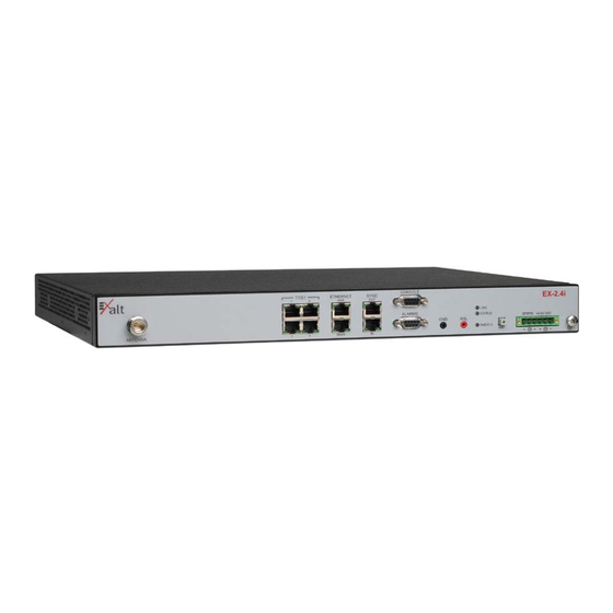
The Exalt i-Series of Digital Microwave Radios The Exalt i-Series of Digital Microwave Radios are the most advanced carrier-class point-to-point terrestrial radio communications devices operating in the 2400 to 2483.5 MHz, 4940 to 4990MHz and 5250 to 5850MHz frequency bands, respectively. Figure 1 shows the EX-2.4i Digital Microwave Radio. - Page 19 Planning of Terrestrial Wireless Links, for detailed information on these activities. The EX-2.4i models utilize radio frequencies in the range of 2400 to 2483.5MHz. The EX-5i models utilize radio frequencies in the range of 5250 to 5850 MHz. In most countries these frequency bands are considered as ‘license-exempt’...
-
Page 20: Basic Features
In almost all cases, either for license-exempt or other designation, the product itself must be authorized for use in your country. Either Exalt or Exalt’s agent must have applied for certification or authorization to allow the sale and deployment of the system within the country. -
Page 21: Figure 2 Indoor Mount Interconnection
Exalt Communications, Inc. Exalt i-Series Installation and Management Guide ANTENNA PRIMARY TRANSMISSION LINE RF LIGHTNING ARRESTOR (GROUNDED) STRUCTURE PENETRATION SECONDARY TRANSMISSION LINE RADIO POWER/DATA/INTERFACES ANTENNA RF LIGHTNING ARRESTOR (GROUNDED) RADIO CABINET GROUNDED POWER/DATA/INTERFACES POWER/DATA/INTERFACES LIGHTNING ARRESTOR(S) STRUCTURE PENETRATION POWER/DATA/INTERFACES Figure 2... - Page 22 Exalt Communications, Inc. Exalt i-Series Installation and Management Guide The i-Series radios feature a wide-mouth direct DC connection (24V or 48V), and are also provided with an external AC adapter. All models provide the following primary features and benefits: • Low-latency optimization and control for voice and data connections •...
-
Page 23: Pre-Installation Tasks
Exalt Communications, Inc. Exalt i-Series Installation and Management Guide Pre-installation Tasks This section describes the steps necessary to prepare a site for the installation of the Exalt Digital Microwave Radio. Link Engineering and Site Planning Design all terrestrial wireless links prior to purchase and installation. Generally, professional wireless engineering personnel are engaged to determine the viability and requirements for a well-engineered link to meet the users’... -
Page 24: Familiarization With I-Series Radios
-16 models). Use the front panel DIP switch, in case of emergency (-16 models only). Exalt recommends using the Exalt GUI for radio configuration. This interface requires a computer with an Ethernet port and web browser software, such as Microsoft Internet Explorer 5.0 or above. -
Page 25: Shipping Box Contents
• Quick-start guide Inspect the outer packaging and the contents of the boxes upon receipt. If you suspect any shipping damage or issues with the contents, contact Exalt Customer Care. Note: Register your system as soon as possible. A 2-year Warranty period applies to products registered within 90 days of purchase. -
Page 26: Back-To-Back Bench Test And Configuration
Exalt i-Series Installation and Management Guide Back-to-Back Bench Test and Configuration Every Exalt digital microwave radio goes through extensive quality testing and performance evaluation over the full operating temperature range prior to shipment. However, before installation, it is strongly advised to perform several tests and tasks that are much more difficult to perform once the radio link endpoints are distant from one another. -
Page 27: Rf Output Power Setting
Exalt Communications, Inc. Exalt i-Series Installation and Management Guide Detailed performance measurements are usually not required for pre-installation, but can be easily performed at this stage and may be helpful for later troubleshooting efforts or for internal records. During troubleshooting, there may often be a point at which a back-... -
Page 28: Link Orientation And Synchronization
Exalt Communications, Inc. Exalt i-Series Installation and Management Guide • Number of supported T1/E1 channels • Ethernet throughput • System latency (delay) Use the ExaltCalc calculator to determine optimum settings for the above parameters to meet the needs of your application. -
Page 29: Radio A/B Configuration
Use the Exalt GUI to configure the radio terminals for Radio A and Radio B orientation. Since many other parameters also need to be set, and the Exalt GUI is needed for these configurations, this is the best way to completely configure the radio terminals. -
Page 30: Radio Synchronization
Radio Synchronization The radio synchronization feature improves the performance of Exalt radios operating in the same frequency band and that are collocated (such as in repeater and hub configurations). Radio synchronization ties radio systems together to operate off of a... -
Page 31: Synchronization Modes
(A) radio. A Global Positioning System (GPS) kit from Exalt is required to implement external source synchronization. GPS synchronization is not available on all radio models. -
Page 32: Figure 5 Collocated Radios, One In Auto Sync Mode To Provide Redundancy
Multiple-link site configuration, using AUTO SYNC for redundancy Note: The configuration shown in Figure 6 is not supported in all models at the time of this writing. Consult your Exalt representative for details. Virtually any combination of hubs and repeater sites, star configurations, and/or backbones can be implemented with synchronization using these configurations. -
Page 33: External Synchronization
This is helpful when Exalt radios are near other devices operating in the same frequency band that also use a timing source, such as GPS. The timing source to the Exalt radios can be adjusted to match the other radio system timing source mechanism. -
Page 34: When Sync Is Lost
This condition is temporary and all interconnected radios re-synchronize to the sync source, as necessary. For GPS synchronization, the wiring inside the Exalt radio carries the GPS signal to the next radio cabled in the system, even when power is removed from the SYNC SOURCE radio or during radio failures. -
Page 35: System Installation And Initiation Process
Exalt Communications, Inc. Exalt i-Series Installation and Management Guide System Installation and Initiation Process The tasks required for radio installation and initiation are outlined in the following figure. Transmission System Tasks Radio Preparation Tasks Read This Path & Site Manual... -
Page 36: Record Keeping
Exalt Communications, Inc. Exalt i-Series Installation and Management Guide Record Keeping After installation, record the following items for ongoing maintenance and future troubleshooting. Keep a record for each end of the radio link and store a copy of these records at the radio location, at the opposite end radio location, and a central record storage location. -
Page 37: Installation
Exalt Communications, Inc. Exalt i-Series Installation and Management Guide Installation This section presents all tasks required to install the Exalt Digital Microwave Radio. Mechanical Configuration and Mounting The i-Series radios are one-piece radio designs intended for deployment in a telecom equipment rack indoors or in an appropriate environmental enclosure. -
Page 38: Figure 11 Front Projection Mount Configuration
Exalt Communications, Inc. Exalt i-Series Installation and Management Guide • Front projection mount (front panel extended forward from the rack mounting surface) Figure 11 Front projection mount configuration • Rear flush mount (rear panel even with the rack mounting surface) •... -
Page 39: Radio Ports And Indicators
This section provides a brief overview of the connectors, controls, and indicators on the device. Details about each item are in other sections of this document. The EX-2.4i front panel is shown in Figure 13. The EX-4.9i and EX-5i front panels are identical, except for the model number shown in the upper-right corner. -
Page 40: Figure 15 Primary Front Panel Connectors (Standard Models)
Exalt Communications, Inc. Exalt i-Series Installation and Management Guide Figure 15 Primary front panel connectors (standard models) Table 2 Connectors Label Type Gender Function Antenna Transmission line connection to GPS antenna. T1/E1 RJ-48C Primary ports for User T1 or E1 circuits to traverse link. -
Page 41: Led Indicators
Exalt Communications, Inc. Exalt i-Series Installation and Management Guide LED Indicators Table 3 provides details of the LED indicators on all models. Table 3 LED indicators Location/Label Type Function LINK 3-color Indicates RF link status: Green Solid = Error-free connection (BER<10e-6) Yellow Solid = Errored connection (10e-3>BER >10e-6) - Page 42 Exalt Communications, Inc. Exalt i-Series Installation and Management Guide Location/Label Type Function T1/E1 Green Solid = Connection present (clocking confirmed) Left Corner Fast Flash = Connection present; coding/clock problem Slow Flash = Connection present, but unexpected Off = No connection/clock...
-
Page 43: Rmt (Remote) Button
Exalt Communications, Inc. Exalt i-Series Installation and Management Guide RMT (Remote) Button The RMT button is the only external control on the radios. This button allows easy and quick evaluation of the status of the remote-end radio. Press and hold the button and, while held, all local-end status LEDs (LINK, STATUS, Radio A) represent the status of the LEDs on the remote-end radio. -
Page 44: Ac Power
RF transmission line. The attenuator must be at least 30dB as specified at the operating frequency (~2400 MHz for the EX-2.4i; ~4950 MHz for the EX-4.9i, ~5700 MHz for the EX-5i), and rated for a minimum of 1W input power. -
Page 45: Dc Power
Exalt Communications, Inc. Exalt i-Series Installation and Management Guide kind of signal interface, the opportunity for damage to the device, loss of communications and property is significant. In some cases, there can also be a risk to human life by not protecting against lightning entering a building through wiring or improper grounding. -
Page 46: Reset To Critical Factory Settings
Exalt Communications, Inc. Exalt i-Series Installation and Management Guide Warning: Consult a qualified electrician if uncertain about how to properly ground the system and connect power. Figure 16 DC connector Once the wires are connected to the mating connector, do not connect to the radio. First test the DC connection to the connector from the DC supply. -
Page 47: Antenna/Transmission System
RF energy. To comply with FCC and Industry Canada regulations, the minimum safe distance from the antenna for continuous human exposure for the EX-2.4i models is 10 feet (3m), 39 inches (1m) for the EX-4.9i, and 10.5 feet (3.2m) for the EX-5i models. -
Page 48: Transmission Line From Antenna To Egress
(generally) of the far end radio, and then slightly tighten the azimuth and elevation adjustments so that the antenna maintains its general position and is safe to be left without additional securing. Refer to the Exalt white paper, Antenna Alignment, for more information on antenna alignment techniques. - Page 49 However, for extremely long transmission lines and/or extremely long radio paths, it may be necessary to use waveguide transmission line instead of coaxial transmission line. In these cases, waveguide type EW20 is recommended for EX-2.4i models (0.45dB/100ft. loss at 2.4GHz), and type EW52 for the EX-4.9i and EX-5i models (1.2dB/100ft.
-
Page 50: Rf Lightning Arrestor
Exalt Communications, Inc. Exalt i-Series Installation and Management Guide The manufacturers of transmission line typically offer instruction and certification for transmission line termination, and may also provide videos illustrating the process. There is no amount of extra care, education, precision, and effort that can be overstated for this process. -
Page 51: Transmission Line From Egress To Radio
Exalt Communications, Inc. Exalt i-Series Installation and Management Guide The following lightning arrestors are examples of proper devices for Exalt Digital Microwave Radios: • Polyphaser AL-LSXM • Andrew BB-BNFNFE-26 Mount and ground the RF lightning arrestor in accordance to the manufacturer’s recommendations. -
Page 52: Antenna Alignment
Antenna Alignment Antennas must be installed at both ends of the planned link to commence precision alignment. Refer to the Exalt white paper, Antenna Alignment. Antennas are typically aligned using the radio hardware for precise alignment. However, there are many very useful tools available to aid in this process, inclusive of devices specifically designed for the purpose of aligning antennas. - Page 53 Only use the browser-based GUI for antenna alignment if there is no other means available. If this method is required, refer to Exalt Graphical User Interface (GUI) on page 54. The RSL reading can be read on a PC or any handheld computing device that supports an HTML browser and Ethernet connectivity.
-
Page 54: Configuration And Management
(GUI). Command Line Interface (CLI) Exalt Digital Microwave Radios provide a CLI to set key parameters on the system. Use the Console port for serial devices, or use the Ethernet MAIN or AUX ports for a Telnet session over a network connection. -
Page 55: Cli Screens And Menus
Exalt Communications, Inc. Exalt i-Series Installation and Management Guide CLI Screens and Menus Use CLI or Telnet when prompted, and enter the administration level login and password. The default administration login is admin and password is password (or admin for early firmware releases). -
Page 56: Exalt Graphical User Interface (Gui)
Exit Exalt Graphical User Interface (GUI) The Exalt GUI is the primary user interface for configuring and troubleshooting the radio and radio system. A computer or hand-held device with a conventional HTML browser and Ethernet port is required. Microsoft Internet Explorer is the preferred browser. -
Page 57: Make Connections
Microsoft Internet Explorer is the recommended browser. Netscape, Mozilla, and Firefox are also supported. If there are issues with your browser, please report it to Exalt Customer Care. You may be required to use a different browser to immediately overcome issues. -
Page 58: Login Privileges
Exalt Communications, Inc. Exalt i-Series Installation and Management Guide The following window displays after pressing the Enter key or clicking the Go button in the browser window. Figure 19 Browser Login screen Login Privileges There are two levels of login privileges: •... -
Page 59: Quick-Start
Exalt Communications, Inc. Exalt i-Series Installation and Management Guide Figure 20 Radio Information page Quick-Start To establish a link on the bench, apply the following basic configurations to the radio terminal. Use the steps in the Quick Start Guide included with the radio. A summary of the items that need to be configured are: •... -
Page 60: Navigating The Gui
Exalt Communications, Inc. Exalt i-Series Installation and Management Guide • Set one radio as Radio A. The radio selected as Radio A must be configured. Radio A/B selection is the Endpoint Identifier parameter on the System Configuration page. Even though both radios are set as Radio B by default, confirm this configuration on the radio intended to be Radio B. -
Page 61: Summary Status Section
Figure 21 Exalt GUI window description Summary Status Section This section of the Exalt GUI provides a review of the system status. Figure 22 Minimized browser windows for summary status of multiple radios In the screens in Figure 22, the top bar illustrates the alarm condition of the link. The background color of this bar is equivalent to the color of the LINK LED on the radio front panel(s) (see Table 3 on page 39). -
Page 62: Navigation Panel
The Summary Status Section allows the Exalt GUI to be a rudimentary management system. Minimize the browser window to display just the top bar or the top bar and radio information, and open several browsers on the desktop. -
Page 63: Radio Information Page
Exalt Communications, Inc. Exalt i-Series Installation and Management Guide Radio Information Page This page provides general information about the local radio terminal. This information is helpful for troubleshooting and for record keeping. Figure 23 Radio Information page 5000001 2007-06-25... -
Page 64: Administration Settings Page
Exalt Communications, Inc. Exalt i-Series Installation and Management Guide Administration Settings Page This page allows contains general parameters for the radio system. The Current Value column lists entries actual settings. Desired changes are entered in the New Value column. After all desired changes are entered, click the Update button to accept and enable changes. - Page 65 • The License Key is set to all zeros. Enter the license key provided by Exalt to access extended features or diagnostic capabilities. Click Update to accept the changes and enable the new features.
-
Page 66: System Configuration Page
Exalt Communications, Inc. Exalt i-Series Installation and Management Guide System Configuration Page This page contains several critical system parameters. Figure 25 System Configuration Page Most entries on this page are self-explanatory. The following lists unique or important parameters: • Set the Radio Transmit Power parameter to the designed level. The professional installer sets this value or dictates the value of this setting to the system administrator following the system design and local regulations. - Page 67 Exalt Communications, Inc. Exalt i-Series Installation and Management Guide Do not adjust the Radio Transmit Power parameter to a value higher than is legally allowed. Do not adjust the Radio Transmit Power parameter lower than the link budget and fade margin can afford.
- Page 68 The frequency selection section includes the ability to select from either the complete list of frequencies (“All”) that can be tuned for the selected band and bandwidth, or a pre-selected list of non-overlapping center frequencies (“Preferred”) that Exalt determined provides the most flexible collocation opportunities for large networks of...
- Page 69 Exalt Communications, Inc. Exalt i-Series Installation and Management Guide • Set the Link Distance parameter to the range that is equal to or greater than the actual link distance. The value of this setting is determined in the design/engineering stage.
-
Page 70: Ethernet Interface Configuration Page
Exalt Communications, Inc. Exalt i-Series Installation and Management Guide Ethernet Interface Configuration Page This page allows the administrator to set the muting, alarm, and duplex settings of both the ETHERNET MAIN and AUX connections. It also allows determination of the management information for in-band (carried over the air and available from both the MAIN and AUX connectors on either end of the link) or out-of-band (not carried over the air and only available from the local AUX connector). -
Page 71: T1/E1 Configuration Pages
Exalt Communications, Inc. Exalt i-Series Installation and Management Guide T1/E1 Configuration Pages These pages allow the administrator to selectively enable or disable the T1 or E1 circuits, one at a time. For enabled T1/E1 circuits, additional configuration, including loopback functions, are available. Disable the unused T1 or E1 so that the alarms are turned off and more throughput is allocated to the Ethernet interface. -
Page 72: E1 Interface Configuration Page
Exalt Communications, Inc. Exalt i-Series Installation and Management Guide Figure 27 T1 Interface Configuration page (standard models) E1 Interface Configuration Page This page allows the administrator to enable/disable each individual E1 channel. The AIS can also be enabled and disabled for each input. If enabled, the radio places an AIS code on the output of the associated interface if and when the link fails or when there is no E1 signal available from the far end to provide the user at the local end. -
Page 73: T1/E1 Loopback
Exalt Communications, Inc. Exalt i-Series Installation and Management Guide Figure 28 E1 Interface Configuration page (standard models) T1/E1 Loopback Loopback is provided for any enabled T1 or E1 port. As shown in Figure 29 and Figure 30, the choices are: •... -
Page 74: Figure 29 External (Remote) Loopback
Exalt Communications, Inc. Exalt i-Series Installation and Management Guide LOCAL REMOTE Figure 29 External (remote) loopback LOCAL REMOTE Figure 30 External (local) loopback When a local T1/E1 port is configured for External (remote) loopback, it is the same as configuring the remote radio for External (local) loopback. -
Page 75: File Transfer Page
Exalt Communications, Inc. Exalt i-Series Installation and Management Guide File Transfer Page This page allows the administrator to upload and download files to and from the radio. Two types of files can be uploaded: configuration and radio firmware. When uploading Configuration Files, current configuration parameters are immediately overwritten, and the unit automatically reboots. -
Page 76: Figure 33 File Transfer Page-Download File Link
A copy of the configuration file can also help restore radio settings. In addition, a copy of the Exalt default configuration file is helpful to restore the radio to factory settings. Note: Do not change the name of any downloaded file. The configuration file must be named config.nv. - Page 77 Exalt Communications, Inc. Exalt i-Series Installation and Management Guide The following parameters can cause problems or confusion if they match at each of a link: • Radio Name • Endpoint Identifier • IP Address • IP Subnet Mask • Default Gateway The following parameters can match at both ends of the link: •...
-
Page 78: File Activation Page
Exalt Communications, Inc. Exalt i-Series Installation and Management Guide File Activation Page Use this page to move stored or uploaded files for use on the radio. The page indicates which file is currently in use, and which file is available for use. Click the Swap button to place the file in the Alternative File column into the active state and move the file in the Current File column to the Alternative File column. -
Page 79: Simple Network Management Protocol (Snmp) Configuration
Dropped links or management control issues do not occur with every parameter change. Many configuration changes do not impact traffic or management access. Exalt radios utilize SNMPv3, a high security version of SNMP, to ensure secure access to and storing of management data. The SNMPv3 security string matches the admin and user passwords. -
Page 80: Alarms Page
Exalt Communications, Inc. Exalt i-Series Installation and Management Guide Alarms Page This page provides an easy-to-read summary of the alarm status of both local and remote radios. The colors on this page reflect the color of the alarms displayed on the radio front panel. - Page 81 Exalt Communications, Inc. Exalt i-Series Installation and Management Guide • The Temperature alarm monitors the internal temperature of the unit based on specific points inside the radio chassis. It is normal for the internal temperature to be above the ambient temperature, so the temperature reading may be higher than the highest specified ambient temperature.
-
Page 82: Performance Page
Exalt Communications, Inc. Exalt i-Series Installation and Management Guide Performance Page This page provides statistical information about the performance of the system in relation to the integrity of the user data and the RF link. Figure 36 Performance page • The Current BER field indicates the current bit error rate of the link. If the link is operating perfectly, this should indicate zero. - Page 83 Exalt Communications, Inc. Exalt i-Series Installation and Management Guide • Current RSL is the measurement of the received signal level at the radio antenna port. This is the measured level of the RF signal coming from the opposite end of the radio link.
- Page 84 Exalt Communications, Inc. Exalt i-Series Installation and Management Guide • Maximum RSL indicates the best (highest) RSL that occurred since the last counter reset. This indicates the best performance of the radio link, which is normally equal to the installed value, and is usually the designed value.
-
Page 85: Event Log Page
Exalt Communications, Inc. Exalt i-Series Installation and Management Guide Event Log Page Use this page to review a list of the events logged by the radio. The following items are listed in the event log: • Alarms • Alarms clearing (Normal) •... - Page 86 Exalt Communications, Inc. Exalt i-Series Installation and Management Guide Every event is tagged with the time that the event occurred, and a severity and type. The event log also allows filtering to limit the view of the log to the lowest level of desired information.
-
Page 87: Diagnostic Charts Page
Exalt Communications, Inc. Exalt i-Series Installation and Management Guide Diagnostic Charts Page Use this page as an aid in troubleshooting. This page illustrates the historical (and current) performance for three parameters: RSL, Radio Temperature, and BER. The horizontal scale illustrates 120 points of time measurement and is synchronized on all three graphs. -
Page 88: Figure 38 Diagnostic Charts Page
Exalt Communications, Inc. Exalt i-Series Installation and Management Guide Figure 38 Diagnostic Charts page Use the cursor to point to any spot on any of the three charts, and all three charts illustrate the measurements taken for that time interval in the upper-left corner of each chart. The time interval is indicated by T=(value). -
Page 89: Spectrum Analyzer Page
Exalt Communications, Inc. Exalt i-Series Installation and Management Guide Changes in RSL often have an impact on BER, and this can be confirmed by looking for synchronized events. When BER events occur without corresponding changes in RSL, this normally indicates interference, atmospheric changes, transmission system issues (such as problems with cables, connectors or antennas), or possibly radio hardware problems. -
Page 90: Reboot Page
Exalt Communications, Inc. Exalt i-Series Installation and Management Guide Reboot Page Use this page to reboot the radio. The function may never be required, but can be used in emergencies. All configurations that require a reboot automatically reboot on administrator confirmation. -
Page 91: Manual Page
Exalt Communications, Inc. Exalt i-Series Installation and Management Guide Manual Page The manual (this document or the version that matches the installed firmware) is available within the GUI. Adobe Acrobat Reader 5.5 or higher is required (go to www.adobe.com to download Acrobat Reader). Click the Manual link and the manual displays within the browser window. -
Page 92: Troubleshooting
The GUI provides information to aid in troubleshooting (see Diagnostic Charts Page on page 85). Contact Exalt Customer Care for further assistance with issues with your Exalt radio and with suggestions on how the radio and documentation can be improved. -
Page 93: Typical Indications Of Issues
Exalt Communications, Inc. Exalt i-Series Installation and Management Guide If the radio link has been operating without issues and is exhibiting new poor performance behavior or becomes completely inoperative, the troubleshooting process should pay close attention to any conditions that may have changed between the time when the system was working without issue and the time when the issues started. -
Page 94: Improper Rf Cable Termination
Exalt Customer Care for assistance. Exalt Customer Care is primarily motivated to determine if the radio hardware is faulty and require return for repair, and to help execute an effective and efficient repair and return process for radio terminals believed to be faulty. -
Page 95: Multipath Propagation
Microwave ovens and wireless communication devices used near the equipment or cabling are examples of electronic equipment interference. Note: The EX-2.4i and EX-5i operate in license-exempt bands. Microwave ovens, wireless Internet devices and cordless phone technology may also use this frequency band. It may be necessary to separate the radio chassis, cabling system and antenna from these devices. -
Page 96: Path Obstruction
– especially if the radio system has low fade margin or is using a high order modulation. The EX-2.4i and EX-5i families provide considerable flexibility to tune to different frequencies across the bands within which they operate. This is the easiest method to use to try to avoid existing interference. -
Page 97: Improper Grounding
Exalt Communications, Inc. Exalt i-Series Installation and Management Guide Improper Grounding In addition to being a potential human safety issue, improper system grounding is a somewhat common condition that can cause continuous bit errors or bit errors when metal objects come in contact with the radio, transmission system, or racking system. If touching the radio causes errors, grounding is the cause. -
Page 98: Specifications
-13° +149°F /-25° to +65°C Altitude 15,000'/4.6 km Humidity 95% non-condensing Safety EN 60950-1, IEC 60950-1 EN 301 489-17 (EX-5i and EX-2.4i series), FCC Part 15, IC Part 15 Common System Specifications Tuning Resolution 1MHz (5MHz for EX-4.9i) Power Control Resolution 0.5dB Selectable Modulation Modes Mode 1 (QPSK);... -
Page 99: Ex-2.4I System Specifications
9M9W7D 16MHz 17M3W7D 19M0W7D 32MHz 34M7W7D 36M0W7D 64MHz* 60M7W7D 61M3W7D * For the EX-2.4i, a firmware option is required to enable 64MHz BW. For the EX-2.4i- 16, 64MHz BW is enabled when the 16xT1/E1 license key is enabled. 5000001 2007-06-25... -
Page 100: Ex-4.9I System Specifications
Exalt Communications, Inc. Exalt i-Series Installation and Management Guide EX-4.9i System Specifications Frequency Band 4940 to 4990 MHz Tunable Range 4945 to 4985 MHz Output Power (at full power, Mode 1) +24dBm (20MHz BW) +22dBm (10MHz BW) Output Power (at minimum power) -
Page 101: Ex-5I System Specifications, 5.3 Ghz Band
Exalt Communications, Inc. Exalt i-Series Installation and Management Guide EX-5i System Specifications, 5.3 GHz Band Frequency Band 5250 to 5350 MHz Tunable Range 5260 to 5332 MHz Output Power (at full power) +13dBm (0.02W) Output Power (at minimum power) -7dBm... -
Page 102: Ex-5I System Specifications, 5.4 Ghz Band
Exalt Communications, Inc. Exalt i-Series Installation and Management Guide EX-5i System Specifications, 5.4 GHz Band Note: Presently this band is not enabled. This band will be enabled through a free software upgrade on regulatory approval. Frequency Band 5470 to 5725 MHz... -
Page 103: Ex-5I System Specifications, 5.8 Ghz Band
Exalt Communications, Inc. Exalt i-Series Installation and Management Guide EX-5i System Specifications, 5.8 GHz Band Frequency Band 5725 to 5850 MHz Tunable Range 5731 to 5844 MHz Output Power (at full power) +24dBm (0.25W), Mode 1 +21dBm (0.13W), Mode 2... -
Page 104: Interfaces
Exalt Communications, Inc. Exalt i-Series Installation and Management Guide Interfaces Connector N-type female Impedance 50 Ohms T1/E1 (x4 or x16) Connector RJ-45 (RJ48C), female T1 Impedance 100 Ohms, balanced T1 Line Codes AMI, B8ZS, selectable T1 LBO Settings (in ft.) - Page 105 Exalt Communications, Inc. Exalt i-Series Installation and Management Guide Sync (In and Out) Connector RJ45, female Signal 1 pps (GPS) Power Connector 6-pin barrier strip Input Voltage (standard models) 20–60VDC Consumption (standard models) <38.5W (0.8A @ 48V; 1.6A @ 24V) Input Voltage (-16 models) 20–60VDC...
-
Page 106: Back-To-Back Bench Testing
Exalt Communications, Inc. Exalt i-Series Installation and Management Guide Back-to-back Bench Testing Use back-to-back bench testing to test the radio before installation, pre-configure the radio and connected equipment before installation, or in the troubleshooting process to identify if the radio hardware is the source of a system issue. It is a critical process, and often required or highly desirable for any installation or troubleshooting exercise. -
Page 107: Specification Performance Verification
Exalt Communications, Inc. Exalt i-Series Installation and Management Guide RF PORTS CONSOLE PORT ATTENUATION RADIO B RADIO A (60-90DB) SERIAL PORT POWER COMPUTER POWER (CONNECT LAST) (CONNECT LAST) Figure 41 Basic back-to-back bench test configuration After connecting and powering on, observe the front panel LEDs to verify that the LINK and STATUS LEDs are green. - Page 108 (including cable losses) that adds to roughly 5 to 15dB less than the system gain. For example, for the EX-2.4i, if the threshold for your measurement is -85dBm, the output power is +27dBm, so the system gain is 112dB. Choose a value of total attenuation in the range of roughly 100–105dB.
-
Page 109: Dc Coupler For Antenna Alignment
Exalt Communications, Inc. Exalt i-Series Installation and Management Guide DC Coupler for Antenna Alignment One challenge associated with an all-indoor radio construction is the alignment of the antennas. It can sometimes be challenging to place the radio near the antenna alignment personnel, and can also be challenging to run a separate set of wires for the voltmeter to be in view of the alignment personnel. -
Page 110: Figure 42 Dc Coupler Interconnection
Exalt Communications, Inc. Exalt i-Series Installation and Management Guide COUPLER (DC SIDE TOWARD RADIO) ANTENNA PRIMARY TRANSMISSION LINE JUMPER CABLE OR ADAPTER (IN PLACE OF LIGHTNING ARRESTOR) STRUCTURE PENETRATION SECONDARY TRANSMISSION LINE RADIO COUPLER (DC SIDE TOWARD ANTENNA) TO RSL PORT... -
Page 111: Interface Connections
Exalt Communications, Inc. Exalt i-Series Installation and Management Guide Interface Connections This section provides the pin number assignment and wiring information for the connectors on the i-Series radios. All connectors are shown as viewed from the radio front panel. T1/E1 Connections There are two orientations of T1/E1 connections. -
Page 112: Ethernet Connections
Exalt Communications, Inc. Exalt i-Series Installation and Management Guide Ethernet Connections There are two orientations of Ethernet connections. AUX has the securing tab towards the top of the connector while MAIN has the securing tab towards the bottom of the connector. -
Page 113: Sync Connections
Exalt Communications, Inc. Exalt i-Series Installation and Management Guide Sync Connections There are two sync connectors: Sync In and Sync Out. The Sync In connector is normally connected to a (custom) GPS antenna system, or to the Sync Out connector of a collocated radio. -
Page 114: Alarm Connector
Exalt Communications, Inc. Exalt i-Series Installation and Management Guide Alarm Connector The Alarm connector provides two alarm outputs that can be connected to external alarm collection equipment. The connector also allows connection of up to two external alarm sources, where the radio will report the status of these connections through the radio network management. -
Page 115: Console Connector
Exalt Communications, Inc. Exalt i-Series Installation and Management Guide Console Connector The Console connector provides a serial interface for the Command Line Interface (CLI) functions. Typically, a straight-through serial cable is used between a computer’s serial port and the Console connector. -
Page 116: Dip Switch Settings (-16 Models Only)
Only use the DIP switch for temporary purposes, for the purpose of a bench test or antenna alignment. Use the Exalt GUI for complete system configuration, as required before final system deployment. -
Page 117: Table 7 Standard Factory Defaults (-16 Models)
Exalt Communications, Inc. Exalt i-Series Installation and Management Guide Table 7 provides the standard factory defaults for the ‘-16’ models. Table 7 Standard Factory Defaults (-16 Models) Parameter EX-2.4i-16 EX-5i-16 Frequency 2441 MHz 5788 MHz Transmit Power +7 dBm +4dBm Link Distance <10 miles... - Page 118 Exalt Communications, Inc. Exalt i-Series Installation and Management Guide Change TDM interfaces to E1 1x1xxxxx Choose the desired reset function using position 4. Reset both radios with position 3 up to configure E1 at each end. One radio must be Radio B, and the other Radio A (using position 2).
-
Page 119: Copyright Notices
Exalt Communications, Inc. Exalt i-Series Installation and Management Guide Copyright Notices This section present copyright notices for third-party software licensed to Exalt Communications, Inc. Net-SNMP The following copyright notice applies to the open-source licensing agreement for Net-SNMP. Copyright 1989, 1991, 1992 by Carnegie Mellon University... - Page 120 Exalt Communications, Inc. Exalt i-Series Installation and Management Guide Network Associates Technology, Inc. Copyright (c) 2001-2003, Networks Associates Technology, Inc All rights reserved. Redistribution and use in source and binary forms, with or without modification, are permitted provided that the following conditions are met: * Redistributions of source code must retain the above copyright notice, this list of conditions and the following disclaimer.
- Page 121 Exalt Communications, Inc. Exalt i-Series Installation and Management Guide TO, THE IMPLIED WARRANTIES OF MERCHANTABILITY AND FITNESS FOR A PARTICULAR PURPOSE ARE DISCLAIMED. IN NO EVENT SHALL THE COPYRIGHT HOLDER BE LIABLE FOR ANY DIRECT, INDIRECT, INCIDENTAL, SPECIAL, EXEMPLARY, OR CONSEQUENTIAL DAMAGES (INCLUDING, BUT NOT LIMITED TO, PROCUREMENT OF SUBSTITUTE GOODS OR SERVICES;...
- Page 122 Exalt Communications, Inc. Exalt i-Series Installation and Management Guide Sparta, Inc. Copyright (c) 2003-2005, Sparta, Inc All rights reserved. Redistribution and use in source and binary forms, with or without modification, are permitted provided that the following conditions are met: * Redistributions of source code must retain the above copyright notice, this list of conditions and the following disclaimer.
- Page 123 Exalt Communications, Inc. Exalt i-Series Installation and Management Guide THIS SOFTWARE IS PROVIDED BY THE COPYRIGHT HOLDERS AND CONTRIBUTORS ''AS IS'' AND ANY EXPRESS OR IMPLIED WARRANTIES, INCLUDING, BUT NOT LIMITED TO, THE IMPLIED WARRANTIES OF MERCHANTABILITY AND FITNESS FOR A PARTICULAR PURPOSE ARE DISCLAIMED.
-
Page 124: Table 9 Product Approvals
Exalt i-Series Installation and Management Guide Appendix A - Regulatory Compliance As of this printing, Exalt Communications, Inc. has approvals for the products that are covered by this manual as indicated in Table 11. If your application or country is not listed, please check with your Sales Representative for the current status. -
Page 125: General Regulatory Notices
Exalt Communications, Inc. Exalt i-Series Installation and Management Guide Romania Slovak Republic Slovenia Spain Sweden Switzerland Turkey United States General Regulatory Notices Dynamic Frequency Selection Dynamic Frequency Selection (DFS) may be required by regional legislation in some frequency bands in order to avoid causing interference to radar systems. Prior to the start... -
Page 126: Table 10
Exalt Communications, Inc. Exalt i-Series Installation and Management Guide Table 10 EX-2.4i supported antennas Manufacturer Model # Description Mid-band 3dB (Azimuth/Elevation) Gain Beamwidth (dBi) (degrees) Andrew 19T-2440-1 16-inch Solid Parabolic Dish 16/17 Andrew 21T-2441-1 24-inch Solid Parabolic Dish 10/11 Andrew... -
Page 127: Table 11 Ex-5I Supported Antennas
Exalt Communications, Inc. Exalt i-Series Installation and Management Guide Table 11 lists antennas supported by the EX-5i family of Digital Microwave Radios. Table 11 EX-5i supported antennas Manufacturer Model # Description Mid-band Gain dBi 3dB (Azimuth/Elevation) Beamwidth (mid-band) (degrees) Andrew... - Page 128 Exalt Communications, Inc. Exalt i-Series Installation and Management Guide Manufacturer Model # Description Mid-band Gain dBi 3dB (Azimuth/Elevation) Beamwidth (mid-band) (degrees) SDF6-52A 6-foot HP Dish 37.4 MA0528-19AN 7.5-inch Panel 19.0 18.0 MA0528-23AN 1-foot Panel 23.0 MA0528-28AN 2-foot Panel 28.0 5000001...
-
Page 129: Region 1 Specifics
Exalt Communications, Inc. Exalt i-Series Installation and Management Guide Region 1 Specifics Region 1 is designated for USA and Canada installations. Note: The professional installer is responsible to ensure that RF output power is properly adjusted to not exceed the regulatory limit. -
Page 130: Industry Canada (Ic), Canada
See RF Output Power Setting on page 25 in this Appendix for details. The antenna associated with EX-2.4i family shall be mounted in a location that is at least 10 feet away from humans that may be subject to long-term or continuous exposure. The antenna associated with the EX-5i family shall be mounted in a location that is at least 10’/3m away from humans that may be subject to long-term or continuous exposure. -
Page 131: Antennas Supported In Canada
Antennas Supported in Canada The EX-2.4i is designed to operate with the antennas listed in Table 10, which have a maximum gain of 30.3 dBi. Antennas not included in the list or having a gain greater than 30.3dBi are prohibited for use with this device. - Page 132 A complete list of allowed antennas can be found in United States Compliance The EX-2.4i and EX-5i product families operate under FCC Rule Parts 15.247 and/or 15.407 as a license-exempt device. The EX-4.9i products operate under FCC Rule Part 90 as a licensed device.
-
Page 133: Ex-2.4I Eirp For The Usa And Canada
Industry Canada (IC), Canada on page 128. EX-2.4i EIRP for the USA and Canada For the EX-2.4i models, the maximum EIRP allowed is +52.2 dBm. The maximum conducted power of the radio is +27 dBm for Mode 1 and +24 dBm for Mode 2. The following formula is used to determine the output power: P = CP –... -
Page 134: Ex-5I Eirp For The Us And Canada
Exalt Communications, Inc. Exalt i-Series Installation and Management Guide EX-5i EIRP for the US and Canada 5250-5350 MHz Band For the EX-5i models within the 5250–5350 MHz band, the maximum transmit power is 30 dBm. The maximum output of the radio is +13 dBm. - Page 135 Exalt Communications, Inc. Exalt i-Series Installation and Management Guide 5725-5850 MHz Band For the EX-5i models within the 5725–5850 MHz band, the maximum EIRP allowed is 61.9 dBm. The maximum output power of the radio is +24 dBm in Mode 1 and +21 dBm in Mode 2.
-
Page 136: Region 2 Specifics
Europe/ITU (ETSI and CE Mark) The EX-2.4i family complies with ETS 300 328 for license-exempt use for most countries recognizing ETSI or ITU band assignments. This band is not yet harmonized for all countries recognizing ETSI or ITU band assignments. There is a +20dBm EIRP limit applied to this band. -
Page 137: Declaration Of Conformity To The R&Tte Directive 1999/5/Ec
EU market after 13 August 2005. Exalt products that are within the scope of the Directives are labeled with a crossed-out "wheelie-bin" symbol as required by the Directives. This indicates that the product was placed on the market after 13 August 2005 and that end-users should segregate the product from other wastes at end-of-life. -
Page 138: Eu Rohs
EU, many of which require presence in the EU. As a result, Exalt’s WEEE compliance approach is to require the distributors and/or resellers in the EU to comply with each country’s national legislation by registration of the distributor or reseller as the producer and for the reseller/distributor to carry out and fulfill the legislative requirements of each national compliance scheme. - Page 139 Exalt Communications, Inc. Exalt i-Series Installation and Management Guide • Use only parabolic dish antennas or directional flat-panel antennas. No other types of antennas (omni-directional, yagi, and so on) are authorized. Parabolic dishes of either grid or solid type are allowed. Maximum mid-band gain of each type of antenna certified is: EX-2.4i models:...
-
Page 140: Ex-2.4I Eirp By Country
Exalt i-Series Installation and Management Guide EX-2.4i EIRP by Country For the EX-2.4i models within the 2400-2483.5 MHz band, the maximum EIRP allowed is 20 dBm and the countries are summarized in Table 12. The maximum output power of the radio is +13 dBm. -
Page 141: Table 12 Region 2 Country Specific Power Levels For Ex-2.4I Series
Exalt Communications, Inc. Exalt i-Series Installation and Management Guide Table 12 Region 2 Country Specific Power Levels for EX- 2.4i Series Country Maximum EIRP Output Power Austria 20 dBm Belgium 20 dBm Cyprus 20 dBm Czech Republic 20 dBm Denmark... -
Page 142: Ex-5I Eirp By Country
Exalt Communications, Inc. Exalt i-Series Installation and Management Guide EX-5i EIRP by Country Table 13 summarizes the maximum power by band and country for Exalt’s EX-5i series products. 5250–5350 MHz band For the EX-5i models within the 5250–5350 MHz band, the maximum transmit power is 23 dBm. - Page 143 EIRP regulations is determined based on the channel bandwidth. The EIRP power limit is 33 dBm for 10 MHz channels and 36 dBm for 20 MHz channels. The Exalt EX-5i series maximum transmitter conducted power is +24 dBm. Use the following equation to determine the EIRP: P = CP –...
-
Page 144: Table 13 Region 2 Country Specific Power Levels For Ex-5I Series
Exalt Communications, Inc. Exalt i-Series Installation and Management Guide Table 13 Region 2 Country Specific Power Levels for EX-5i Series Country Maximum EIRP Output Maximum EIRP Output Maximum EIRP Output Power, 5.3 GHz band Power, 5.4 GHz band Power, 5.8 GHz band... -
Page 145: Index
Exalt Communications, Inc. Exalt i-Series Installation and Management Guide Index main menu, 53 menu options, 53 clock, 32 AC adapter, 41, 42 configuration file, 73 accessory kit contents, 23 connectors Administration Settings page, 62 40-60VDC, 38 administrator privileges, 56 Alarm, 112... - Page 146 Exalt Communications, Inc. Exalt i-Series Installation and Management Guide Ethernet interface, 102 throughput settings, 69 Ethernet Interface Configuration page, 68 interfaces ETHERNET MAIN/AUX LED, 39 alarm, 102 Event Log page, 83 Ethernet, 102 ExaltCalc tool, 26, 91 power, 103 External Alarm Inputs parameter, 67...
- Page 147 Exalt Communications, Inc. Exalt i-Series Installation and Management Guide Minimum RSL field, 81 radio mount Minimum RSL Timestamp field, 81 enclosure, 18 Mode parameter, 65 connections, 19 modes indoor, 18 AUTO SYNC, 29 connections, 19 multi-link backbone, 30 Radio Name parameter, 75...
- Page 148 Exalt Communications, Inc. Exalt i-Series Installation and Management Guide System Configuration page, 64 temperature, 85, 96 system latency, 21 Temperature alarm, 79 system parameters temporary hardware configuration key, 22, 28, 54 default settings, 44 testing, 104 system performance, 80 back-to-back bench, 24...
- Page 149 Exalt Communications, Inc. Exalt i-Series Installation and Management Guide © 2007 Exalt Communications Inc. 580 Division St. Campbell, CA 95008 USA 5000001 2007-05-31...
Need help?
Do you have a question about the EX-2.4i and is the answer not in the manual?
Questions and answers