Exalt EX-2.4i Installation And Management Manual
Ex-i series
digital microwave radios
Hide thumbs
Also See for EX-2.4i:
- Installation and management manual (149 pages) ,
- Installation and maintenance manual (49 pages) ,
- Quick start manual (4 pages)
Table of Contents
Advertisement
Advertisement
Table of Contents

Related Manuals for Exalt EX-2.4i


Summary of Contents for Exalt EX-2.4i
- Page 1 Exalt Installation and Management Guide EX-i Series (TDD) EX-i Series (TDD) Digital Microwave Radios Installation and Management Guide Models: EX-2.4i/EX-2.4i Lite EX-2.4i-16/EX-2.4i-16 K EX-4.9i EX-5i/EX-5i Lite EX-5i-16/EX-5i-16 K EX-5i-DS3 206501-019 2016-05-24...
-
Page 2: Open-Source License Information
Third Party Licenses, which licenses give you at least the license rights licensed to you in the Exalt End User Agreement and may give you additional license rights as to the Third Party Software, but only with respect to the particular Third Party Software to which the Third Party License applies. -
Page 3: Table Of Contents
The Exalt i-Series Digital Microwave Radios ........ - Page 4 Exalt Graphical User Interface (GUI) ........
- Page 5 EX-2.4i System Specifications ........
- Page 6 EX-2.4i EIRP for the USA and Canada ........
-
Page 7: List Of Figures
Front panel (EX-2.4i, EX-4.9i, or EX-5i) ........ - Page 8 Table 13 Regulatory Domain Keys ..........119 Table 14 EU and ITU Country-Specific EIRP Levels for the EX-2.4i Series ....122 Table 15 EU and ITU Country Specific EIRP Levels for EX-5i Series .
-
Page 9: About This Document
EX-i Series (TDD) Digital Microwave Radios About this Document This manual provides a complete description of the EX-i Series (TDD) of Exalt Digital Microwave Radios and related software. This manual provides planners, engineers, installers, system administrators, and technicians general and specific information related to the planning, installation, operation, management, and maintenance of these devices. -
Page 10: Icons
Exalt Installation and Management Guide EX-i Series (TDD) Digital Microwave Radios Icons The following icons denote specific types of information: Note: This symbol means take note. Notes contain helpful suggestions or references to materials not contained in the manual. Warning! This symbol means there is a risk of electric shock or bodily injury. Before working on any equipment, be aware of the hazards involved with electrical circuitry and be familiar with standard practices for preventing accidents. -
Page 11: Introduction
EX-i Series (TDD) Digital Microwave Radios Introduction Exalt Wireless, Inc. thanks you for your purchase. Our goal is to build the highest quality, highest reliability digital microwave radio products. This commitment to quality and reliability extends to our employees and partners alike. We appreciate any comments on how we can improve our products, as well as your sales and Customer Care experience.f... - Page 12 With license-key upgrade for 4xT1/E1 – With license-key upgrade for FIPS-197 compliant 128-bit or 256-bit AES encryption • EX-2.4i-16 (or EX-2.4i-16 K, exclusively for Korea), 10/100 Ethernet + 16xT1/E1 – Configured for 4xT1/E1, 100Mbps (32MHz/Mode2) – With license-key upgrade for 8xT1/E1, 100Mbps (32MHz/Mode2) –...
- Page 13 The EX-2.4i models utilize radio frequencies in the range of 2400 to 2483.5MHz. The EX-5i models utilize radio frequencies in the range of 5250 to 5850 MHz. In most countries these frequency bands are considered as ‘license-exempt’...
-
Page 14: Figure 2 Indoor Mount Interconnection
Exalt or your authorized Exalt representative for information pertaining to your country. Note: It is the professional installer’s responsibility to ensure that the radio system is implemented in a legal fashion. Exalt is not liable for any unsafe or illegal installations. Figure 2 Indoor mount interconnection... - Page 15 Exalt Installation and Management Guide EX-i Series (TDD) Digital Microwave Radios • 10/100BaseT Ethernet • Up to 16xT1/E1 interfaces for synchronous voice traffic (number of TDM interfaces is determined by specific model and license-key configuration) • Up to 1xDS-3 interface for synchronous voice traffic The i-Series radios feature a wide-mouth direct DC connection (24V or 48V), and are also provided with an external AC adapter.
-
Page 16: Pre-Installation Tasks
Exalt Installation and Management Guide EX-i Series (TDD) Digital Microwave Radios Pre-installation Tasks This section describes the steps necessary to prepare a site for the installation of the Exalt Digital Microwave Radio. Link Engineering and Site Planning Design all terrestrial wireless links prior to purchase and installation. Generally, professional wireless engineering personnel are engaged to determine the viability and requirements for a well-engineered link to meet the users’... -
Page 17: Shipping Box Contents
Telnet on the AUX port or a Serial connection to the Console port. Use the front panel DIP switch, in case of emergency (EX-2.4i-16 model only). Exalt recommends using the Exalt GUI for radio configuration. This interface requires a computer with an Ethernet port and web browser software, such as Microsoft Internet Explorer 5.0 or above. -
Page 18: Initial Configuration And Back-To-Back Bench Test
Administration Settings Page of the Exalt GUI. The RDK references the unit's serial number and is provided based on the country and/or region where the radio system will be deployed. The RDK is obtained through your Exalt Authorized distributor or reseller. -
Page 19: Rf Output Power Setting
Exalt Installation and Management Guide EX-i Series (TDD) Digital Microwave Radios – Set link distance, occupied channel bandwidth, and frame length • Make detailed radio performance measurements – Measure transmitter output power – Measure receiver threshold performance – Confirm unfaded error-free performance Some of these tasks may not be possible or practical within a bench test environment due to the nature of the remote connectivity of peripheral equipment. -
Page 20: Link Orientation And Synchronization
Note: It is not always necessary to synchronize collocated radios. If antennas are substantially separated or blocked from one another and/or frequency separation tuning is used, the opportunity for near-end interference can be eliminated. Note: The GPS sync feature is not available on all models. Contact your Exalt Wireless representative for details. 206501-019... -
Page 21: Radio A/B Configuration
Use the Exalt GUI to configure the radio terminals for Radio A and Radio B orientation. Since many other parameters also need to be set, and the Exalt GUI is needed for these configurations, this is the best way to completely configure the radio terminals. -
Page 22: Radio Synchronization
EX-i Series (TDD) Digital Microwave Radios Radio Synchronization The radio synchronization feature improves the performance of Exalt radios operating in the same frequency band and that are collocated (such as in repeater and hub configurations). Radio synchronization ties radio systems together to operate off of a common clock system, ensuring that all radios simultaneously transmit and receive, and thus eliminating near-field interference issues and related radio system coupling. -
Page 23: External Synchronization
Bandwidth – It is desirable, but not always necessary, to match the bandwidth for all collocated links. For complex networks, an Exalt engineer should review multi-link networks before deployment as several factors can optimize the network for desired performance. External Synchronization Use an external GPS source as an alternative to the internal synchronization source for system synchronization. -
Page 24: Offset Timing
This is helpful when Exalt radios are near other devices operating in the same frequency band that also use a timing source, such as GPS. The timing source to the Exalt radios can be adjusted to match the other radio system timing source mechanism. -
Page 25: When Sync Is Lost
Exalt’s VLAN communications implementation adheres to the IEEE standard 802.1q. In most cases, an Exalt radio acting as a Layer 2 bridge between two locations is only required to pass traffic with VLAN tagging. Without additional configuration, all Exalt radios support frame sizes in excess of 1900 bytes, which currently supports all defined VLAN packet sizes. -
Page 26: Link Symmetry
WANs. Exalt does not recommend placing two links with asymmetry back-to-back in a serial configuration due to the TDD cycle of the radios. This configuration requires that one radio transmits in an overlapping time period while another radio is receiving. -
Page 27: Simple Network Management Protocol (Snmp)
Exalt radios utilize SNMPv3, a high security version of SNMP, to ensure secure access to and storing of management data. The SNMPv3 security string matches the admin and user passwords. Passwords must be eight characters or longer. -
Page 28: System Installation And Initiation Process
Exalt Installation and Management Guide EX-i Series (TDD) Digital Microwave Radios System Installation and Initiation Process The tasks required for radio installation and initiation are outlined in the following figure. Transmission System Tasks Radio Preparation Tasks Read This Path & Site... -
Page 29: Record Keeping
Exalt Installation and Management Guide EX-i Series (TDD) Digital Microwave Radios Record Keeping After installation, record the following items for ongoing maintenance and future troubleshooting. Keep a record for each end of the radio link and store a copy of these records at the radio location, at the opposite end radio location, and a central record storage location. -
Page 30: Installation
All RF connectors, cables, and adapters must be rated for operation within the radio’s frequency range (2400–2483.5 MHz for EX-2.4i; 4940–4990 MHz for EX-4.9i; 5250–5850 MHz for EX-5i). RF connector losses must be accounted for within the link engineering design and output power settings. -
Page 31: Radio Ports And Indicators
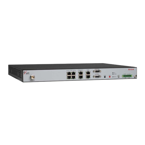
The EX-2.4i front panel is shown in Figure 13. The EX-4.9i and EX-5i front panel are identical to the EX-2.4i model, except for the model number shown in the upper-right corner. -
Page 32: Connector Overview
Exalt Installation and Management Guide EX-i Series (TDD) Digital Microwave Radios The EX-2.4i-16 front panel is shown in Figure 14. The EX-5i-16 front panel is identical, except for the model number shown in the upper-right corner. Figure 14 Front panel (EX-2.4i-16 or EX-5i-16) The EX-5i-DS3 model front panel is shown in Figure 15. -
Page 33: Led Indicators
Exalt Installation and Management Guide EX-i Series (TDD) Digital Microwave Radios Table 2 Connectors (Continued) Label Type Gender Function GND (Ground) Bantam Common (return) volt meter test point for measuring RSL. Bantam Voltmeter test point for measuring received signal level. - Page 34 Exalt Installation and Management Guide EX-i Series (TDD) Digital Microwave Radios Table 3 LED indicators (Continued) Locat i on/ Label Type Funct i on 3-color Indicates DS3 connection status: Green Solid = No alarm conditions (normal operation) Yellow Solid = DS3 signal present, but DS3 is not enabled...
-
Page 35: Rmt (Remote) Button
RF transmission line. The attenuator must be at least 30dB as specified at the operating frequency (~2400 MHz for the EX-2.4i; ~4950 MHz for the EX-4.9i; ~5700 MHz for the EX-5i), and rated for a minimum of 1W input power. Examples include: –... -
Page 36: Ac Power
DC Power The device accepts DC power within the voltage specifications. For some EX-2.4i terminals, the DC voltage is 48 volts, nominal. For all other i-Series models, the DC voltage input accepts either 24 volts or 48 volts, nominal. -
Page 37: Figure 18 Dc Connector
Exalt Installation and Management Guide EX-i Series (TDD) Digital Microwave Radios To connect a DC source, with the power disabled on the DC supply, connect proper gauge wiring to the DC supply. For most (short) power cable runs, 18AWG or 24AWG wire can be typically used. Strip the ends just long enough for enclosure to the DC radio connector (approximately 0.25 inches/6mm). -
Page 38: Reset To Critical Factory Settings
Exalt Installation and Management Guide EX-i Series (TDD) Digital Microwave Radios Power regarding fusing, breakers, lightning protection, surge protection and power conditioning. Follow these recommendations for a DC supply. Reset to Critical Factory Settings If necessary, the radio terminal may be reset to critical factory settings. This may be necessary if the IP address and/or passwords for the system are not known. -
Page 39: Initial Antenna Mounting
Refer to the Exalt white paper, Antenna Alignment, for more information on antenna alignment techniques. -
Page 40: Table 4 Recommended Transmission Line
EX-i Series (TDD) Digital Microwave Radios Consult the path or site engineer(s) to ensure that the proper materials are chosen for the installation and that all factors were considered. Refer to the Exalt white paper, Transmission Line for Exalt Indoor Radio Systems. -
Page 41: Rf Lightning Arrestor
The RF lightning arrestor prevents any associated voltage and current from entering the building or enclosure, where it might harm the radio equipment, other equipment, or humans. The following lightning arrestors are examples of proper devices for Exalt Digital Microwave Radios: 206501-019 2016-05-24... -
Page 42: Transmission Line From Egress To Radio
Antenna Alignment Antennas must be installed at both ends of the planned link to commence precision alignment. Refer to the Exalt white paper, Antenna Alignment. Antennas are typically aligned using the radio hardware for precise alignment. However, there are many very useful tools available to aid in this process, inclusive of devices specifically designed for the purpose of aligning antennas. - Page 43 Exalt Installation and Management Guide EX-i Series (TDD) Digital Microwave Radios – Temporarily connect the radio to the antenna using a short piece of transmission line, so that the radio is very close to the antenna location – Run wires, as necessary, from the RSL test point to the volt meter so that the antenna...
-
Page 44: Configuration And Management
After establishing the serial connection, press ENTER to display the login prompt. Telnet into the Command Line Interface (CLI) Use a Telnet connection to access the CLI in the Exalt Digital Microwave Radios. Use the CLI to set key parameters on the system. -
Page 45: Exalt Graphical User Interface (Gui)
Ctrl+\ (control and backslash keys) = exit session Exalt Graphical User Interface (GUI) The Exalt GUI is the primary user interface for configuring and troubleshooting the radio and radio system. A computer or hand-held device with a conventional HTML browser and Ethernet port is required. -
Page 46: Log In
If the radio supports DHCP and DHCP is enabled (see Ethernet Interface Configuration Page), which is the default setting for a radio shipped from Exalt (for the models with this feature), and your computer’s Ethernet port is set for DHCP addressing, the radio will configure your computer to an IP address value which is either 2 or 10 higher than the radio’s... -
Page 47: Login Privileges
Exalt Installation and Management Guide EX-i Series (TDD) Digital Microwave Radios Figure 21 Browser Login screens–model dependent Note: Some models support SSL/SSH secure browser management, and display the login screen on the right. Browser security can be enabled or disabled for these models. -
Page 48: Quick Start
– RDK references the unit’s serial number and the country/region where the radio will be deployed. – RDK is obtained through your Exalt Authorized reseller or distributor. • Set one radio as Radio A. – The radio selected as Radio A must be configured. -
Page 49: Navigating The Gui
Figure 23 Exalt GUI window description Summary Status Section This section of the Exalt GUI provides a review of the system status. Note: Click the radio IP address link to access that radio for management. In the screens in Figure 23, the top bar illustrates the alarm condition of the link. The information inside the bar is equivalent to the entry of the Link Name set by the administrator in the Administration Settings page. -
Page 50: Navigation Panel
The Summary Status Section allows the Exalt GUI to be a rudimentary management system. Minimize the browser window to display just the top bar or the top bar and radio information, and open several browsers on the desktop. - Page 51 Exalt Installation and Management Guide EX-i Series (TDD) Digital Microwave Radios Note: The ‘local’ radio might be the near-end or the far-end radio, depending on the management interface connection. The terms local and remote refer to the orientation of the radio terminals relative to the IP address you are managing.
-
Page 52: Radio Information Page
Exalt Installation and Management Guide EX-i Series (TDD) Digital Microwave Radios Radio Information Page This page provides general information about the local radio terminal. This information is helpful for troubleshooting and for record keeping. Figure 25 Radio Information page 206501-019... -
Page 53: Administration Settings Page
Exalt Installation and Management Guide EX-i Series (TDD) Digital Microwave Radios Administration Settings Page This page allows contains general parameters for the radio system. The Current Value column lists entries actual settings. Desired changes are entered in the New Value column. - Page 54 The RDK must be typed in to enable ANY functionality for the radio. The RDK is issued to the Exalt Authorized distributor or reseller, and is paired to the specific serial number of the radio.
-
Page 55: Simple Network Management Protocol (Snmp) Configuration
Exalt Installation and Management Guide EX-i Series (TDD) Digital Microwave Radios Simple Network Management Protocol (SNMP) Configuration This page allows the enabling and disabling of the Simple Network Management Protocol (SNMP) functions. Use SNMP to manage networked devices and execute the following functions: •... -
Page 56: Snmp Traps
Exalt Installation and Management Guide EX-i Series (TDD) Digital Microwave Radios Note: Users are encouraged to avoid enabling SNMPv1/V2c support due to known security loopholes in these protocols. Enable the SNMPv3 options to allow entering read and read/write user names and passwords. These entries are de-coupled from the standard radio user names and passwords. - Page 57 • Local/Remote Link Status Trap: This trap is sent when Link is in erroreds state (equivalent to the Link LED on the radio front panel or the Link status bar in the upper-left of the Exalt GUI window). •...
-
Page 58: File Transfer Page
Swap button). The current radio firmware and RDD versions can be viewed on the Radio Information Page. Note: Issues with the RDK may be caused when the Regulatory Domain Database (RDD) is not up to date. Go to the Exalt Web site to download the current RDD. 206501-019 2016-05-24... -
Page 59: Figure 31 File Transfer Page-Download File Link
File download and upload is useful when configuring several radios with similar settings. A copy of the configuration file can also help restore radio settings. In addition, a copy of the Exalt default configuration file is helpful to restore the radio to factory settings. - Page 60 Exalt Installation and Management Guide EX-i Series (TDD) Digital Microwave Radios • IP Subnet Mask • Default Gateway The following parameters can match at both ends of the link: • Link Name • Link Security Key (although each link should be different) •...
-
Page 61: File Activation Page
Exalt Installation and Management Guide EX-i Series (TDD) Digital Microwave Radios File Activation Page Use this page to move stored or uploaded files for use on the radio. The page indicates which file is currently in use, and which file is available for use. Click the Swap button to place the file in the Alternative File column into the active state and move the file in the Current File column to the Alternative File column. -
Page 62: Access Security Page
Exalt Installation and Management Guide EX-i Series (TDD) Digital Microwave Radios Access Security Page Note: As of this writing, this feature is not yet released on all models. This feature allows all radio management interfaces such as HTTP, HTTPS, SSH, Telnet, and serial to be independently disabled/enabled. - Page 63 TDM traffic (T1, E1, DS3), where serial access is sufficient. This feature is not available on all models. Root access is used by Exalt for remote software diagnosis (if the radio is accessible over the Internet to Exalt and login credentials were provided). Root access is enabled by default.
-
Page 64: System Configuration Page
Exalt Installation and Management Guide EX-i Series (TDD) Digital Microwave Radios System Configuration Page This page contains several critical system parameters. Figure 34 System Configuration page Note: For models requiring a Regulatory Domain Key (RDK), you must enter a valid RDK to edit this page. - Page 65 (“All”) that can be tuned for the selected band and bandwidth, or, in some cases, a pre- selected list of non-overlapping center frequencies (“Preferred”) that Exalt determined provides the most flexible collocation opportunities for large networks of Exalt radios The frequency selection section includes a band selection button that must be enabled for the frequency band of operation for which the link was engineered.
- Page 66 Exalt Installation and Management Guide EX-i Series (TDD) Digital Microwave Radios on the active RDK. DFS is automatically enabled for these bands and is selectable for all other bands. Note: Changing RF Frequency will temporarily interrupt traffic. The RF Frequency parameter setting must match at each end.
- Page 67 Exalt Installation and Management Guide EX-i Series (TDD) Digital Microwave Radios Note: Changing the TDD Frame Size parameter will temporarily interrupt traffic. TDD Frame Size parameters must match at each end. Adjust the far-end radio first, and then the near-end radio. If the TDD Frame Size parameter is set to a value that cannot be supported for the link distance, the link may be lost and unrecoverable through GUI control.
-
Page 68: Mhs Configuration Page
Exalt Installation and Management Guide EX-i Series (TDD) Digital Microwave Radios MHS Configuration Page The -16 versions provide the Monitored Hot Standby (MHS) feature. The MHS kit is sold separately and requires a valid license key, which is included with the kit. The radio system can be configured for hardware redundancy at either end or both ends of the radio link. -
Page 69: Ethernet Interface Configuration Page
Exalt Installation and Management Guide EX-i Series (TDD) Digital Microwave Radios Ethernet Interface Configuration Page This page allows the administrator to set the muting, alarm, and duplex settings of both the ETHERNET MAIN and AUX connections. It also allows determination of the management information for in-band (carried over the air and available from both the MAIN and AUX connectors on either end of the link) or out-of-band (not carried over the air and only available from the local AUX connector). -
Page 70: Vlan Configuration Page
VLAN Configuration Page VLAN is disabled as the default setting for Exalt radios. The Exalt radios still pass VLAN and non- VLAN traffic across the link, but do not examine the VLAN traffic or act upon it. Enable VLAN using the Exalt GUI for expanded VLAN support. - Page 71 Exalt Installation and Management Guide EX-i Series (TDD) Digital Microwave Radios the following methods to restore the management connection if a mistake was made assigning the management VLAN and access cannot be restored: • Reset the radio to the critical factory defaults (see Reset to Critical Factory Settings).
-
Page 72: T1/E1 Configuration Pages
Exalt Installation and Management Guide EX-i Series (TDD) Digital Microwave Radios T1/E1 Configuration Pages These pages allow the administrator to selectively enable or disable the T1 or E1 circuits, one at a time. For enabled T1/E1 circuits, additional configuration, including loopback functions, are available. -
Page 73: E1 Interface Configuration Page
Exalt Installation and Management Guide EX-i Series (TDD) Digital Microwave Radios Figure 38 T1 Interface Configuration page E1 Interface Configuration Page This page allows the administrator to enable/disable each individual E1 channel. The AIS can also be enabled and disabled for each input. If enabled, the radio places an AIS code on the output of the associated interface if and when the link fails or when there is no E1 signal available from the far end to provide the user at the local end. -
Page 74: T1/E1 Loopback
Exalt Installation and Management Guide EX-i Series (TDD) Digital Microwave Radios T1/E1 Loopback Loopback is provided for any enabled T1 or E1 port. As shown in Figure 38 and Figure 39, the choices are: • No Loopback (default) • External (local) •... -
Page 75: Ds3 Configuration Page
Exalt Installation and Management Guide EX-i Series (TDD) Digital Microwave Radios DS3 Configuration Page This page allows the administrator to configure the DS3 interface (EX-5i-DS3 model only). The interface should be disabled if there is no DS3 connected. The associated throughput is then allocated to T1/E1 and/or Ethernet. -
Page 76: Gps Information Page
EX-i Series (TDD) Digital Microwave Radios GPS Information Page This page provides information on how many GPS satellites are within the view of the Exalt GPS receiver. This page is active for implementations that include the GPS receiver connection for synchronization. -
Page 77: Alarms Page
Exalt Installation and Management Guide EX-i Series (TDD) Digital Microwave Radios Alarms Page This page provides an easy-to-read summary of the alarm status of both local and remote radios. The colors on this page reflect the color of the alarms displayed on the radio front panel. However, additional detail displays on this page to aid in quick assessment of issues and status. - Page 78 Exalt Installation and Management Guide EX-i Series (TDD) Digital Microwave Radios Table 6 Alarm status indicators (Continued) Label Status Indicates the status of the DS3 interface. Green = Enabled and connection present Yellow = Disabled and connection present Red = Enabled and no connection present Grey = Disabled or unavailable due to configuration Ethernet –...
-
Page 79: Mhs Status Page
Exalt Installation and Management Guide EX-i Series (TDD) Digital Microwave Radios MHS Status Page Note: MHS is a future enhancement. For -16 models with the MHS option, the MHS Status page shows the present alarm status of the MHS functions. Figure 45 shows the MHS Status page. -
Page 80: Performance Page
Exalt Installation and Management Guide EX-i Series (TDD) Digital Microwave Radios Performance Page This page provides statistical information about the performance of the system in relation to the integrity of the user data and the RF link. Figure 46 Performance page •... - Page 81 Exalt Installation and Management Guide EX-i Series (TDD) Digital Microwave Radios • Errored Seconds (ES) indicates the total number of seconds that occurred where there was at least one bit error since the last time that the radio statistics counter was reset. Generally, ES are not a significant concern, so long as they are not continuous or above the anticipated performance based on the original link engineering goals.
-
Page 82: Event Log Page
Exalt Installation and Management Guide EX-i Series (TDD) Digital Microwave Radios Event Log Page Use this page to review a list of the events logged by the radio. The following items are listed in the event log: • Alarms •... -
Page 83: User Throughput Page
Exalt Installation and Management Guide EX-i Series (TDD) Digital Microwave Radios User Throughput Page This page illustrates the user throughput of the radio, as configured. Figure 48 User Throughput page Click the help icon ( ) to go to page on how this information is determined (Figure 49). -
Page 84: Figure 49 Aggregate User Throughput Help Page
Exalt Installation and Management Guide EX-i Series (TDD) Digital Microwave Radios Figure 49 Aggregate User Throughput Help page 206501-019 2016-05-24... -
Page 85: Diagnostic Charts Page
Exalt Installation and Management Guide EX-i Series (TDD) Digital Microwave Radios Diagnostic Charts Page Use this page as an aid in troubleshooting. This page illustrates the historical (and current) performance for three parameters: RSL, Radio Temperature, and BER. The horizontal scale illustrates 120 points of time measurement and is synchronized on all three graphs. - Page 86 Exalt Installation and Management Guide EX-i Series (TDD) Digital Microwave Radios Changes in RSL often have an impact on BER, and this can be confirmed by looking for synchronized events. When BER events occur without corresponding changes in RSL, this normally indicates interference, atmospheric changes, transmission system issues (such as problems with cables, connectors, or antennas), or possibly radio hardware problems.
-
Page 87: Spectrum Analyzer Page
Exalt Installation and Management Guide EX-i Series (TDD) Digital Microwave Radios Spectrum Analyzer Page The spectrum analyzer feature provides a useful pre-planning and troubleshooting tool. This feature is only available on radios with firmware supporting the spectrum analyzer. Perform a spectrum analysis after deployment and just before commissioning to maintain a record of the spectrum at the time of deployment. -
Page 88: Figure 52 Spectrum Analyzer Graph Example
Exalt Installation and Management Guide EX-i Series (TDD) Digital Microwave Radios Note: Enabling the spectrum analyzer interrupts all radio traffic for the duration of the analysis. In addition, access to the radio’s GUI may also be interrupted, depending on the location of the interfaced computer relative to the radio where the spectrum analysis is occurring. -
Page 89: Ethernet Utilization Page
Exalt Installation and Management Guide EX-i Series (TDD) Digital Microwave Radios Ethernet Utilization Page This page shows a chart for each Ethernet interface to illustrate inbound and outbound packet utilization. This is shown as a percentage of the interface configuration (that is, if your interface is set for 100BaseT, then 100% represents 100Mbps. -
Page 90: Reboot Page
Exalt Installation and Management Guide EX-i Series (TDD) Digital Microwave Radios Reboot Page Use this page to reboot the radio. The function may never be required, but can be used in emergencies. All configurations that require a reboot automatically reboot on administrator confirmation. -
Page 91: Manual Page
Exalt Installation and Management Guide EX-i Series (TDD) Digital Microwave Radios Manual Page The manual (this document or the version that matches the installed firmware) is available within the GUI. Adobe Acrobat Reader 5.5 or higher is required (go to www.adobe.com... -
Page 92: Specifications
96-bit Security Code, optional NIST FIPS-197 compliant 128-bit or 256-bit AES encryption. Not all bandwidth and mode combinations are available on all radio models. Some radios may require specific software license keys, which can be purchased from your authorized Exalt representative. 206501-019 2016-05-24... -
Page 93: Ex-2.4I System Specifications
Mode 2 8MHz 10M2W7D 9M9W7D 16MHz 17M3W7D 19M0W7D 32MHz 34M7W7D 36M0W7D 64MHz* 60M7W7D 61M3W7D 64MHz BW is enabled for the EX-2.4i though a firmware option. 64MHz BW is enabled for the EX-2.4i-16 when the 16xT1/E1 license key is enabled. 206501-019 2016-05-24... -
Page 94: Ex-4.9I System Specifications
Exalt Installation and Management Guide EX-i Series (TDD) Digital Microwave Radios EX-4.9i System Specifications Frequency Band 4940 to 4990 MHz Tunable Range 4945 to 4985 MHz Output Power (at full power, Mode 1) +24dBm (20MHz BW) +22dBm (10MHz BW) Output Power (at minimum power) -
Page 95: Ex-5I System Specifications, 5.3Ghz Band
Exalt Installation and Management Guide EX-i Series (TDD) Digital Microwave Radios EX-5i System Specifications, 5.3GHz Band Frequency Band 5250 to 5350 MHz Tunable Range 5260 to 5332 MHz Output Power (at full power) +13dBm (0.02W) Output Power (at minimum power) -
Page 96: Ex-5I System Specifications, 5.4Ghz Band
Exalt Installation and Management Guide EX-i Series (TDD) Digital Microwave Radios EX-5i System Specifications, 5.4GHz Band Frequency Band 5470 to 5725 MHz Tunable Range 5488 to 5715 MHz Output Power (at full power) +13dBm (0.02W) Output Power (at minimum power) -
Page 97: Ex-5I System Specifications, 5.8Ghz Band
Exalt Installation and Management Guide EX-i Series (TDD) Digital Microwave Radios EX-5i System Specifications, 5.8GHz Band Frequency Band 5725 to 5850 MHz Tunable Range 5731 to 5844 MHz Output Power (at full power) +24dBm (0.25W), Mode 1 +21dBm (0.13W), Mode 2... -
Page 98: Interfaces
Exalt Installation and Management Guide EX-i Series (TDD) Digital Microwave Radios Interfaces Connector N-type female Impedance 50 Ohms T1/E1 (x4 or x16) Connector RJ-45 (RJ48C), female T1 Impedance 100 Ohms, balanced T1 Line Codes AMI, B8ZS, selectable T1 LBO Settings (in ft.) - Page 99 1 pps (GPS) Power Connector 6-pin barrier strip Input Voltage (EX-2.4i) 40–60VDC (most EX-2.4i radios conform to the same power as EX-5i below, the front panel of the radio indicates the proper input per the manufacturing date of the radio) Consumption (EX-2.4i) <34W (0.7A @ 48V)
-
Page 100: Interface Connections
Exalt Installation and Management Guide EX-i Series (TDD) Digital Microwave Radios Interface Connections This section provides the pin number assignment and wiring information for the connectors on the i-Series radios. All connectors are shown as viewed from the radio front panel. -
Page 101: Ethernet Connections
Exalt Installation and Management Guide EX-i Series (TDD) Digital Microwave Radios Ethernet Connections There are two orientations of Ethernet connections. AUX has the securing tab towards the top of the connector while MAIN has the securing tab towards the bottom of the connector. Figure 57 illustrates the pin orientation and functionality of these connectors. -
Page 102: Sync Connections
Exalt Installation and Management Guide EX-i Series (TDD) Digital Microwave Radios Sync Connections There are two sync connectors: Sync In and Sync Out. The Sync In connector is normally connected to a (custom) GPS antenna system, or to the Sync Out connector of a collocated radio. -
Page 103: Alarm Connector
Exalt Installation and Management Guide EX-i Series (TDD) Digital Microwave Radios Alarm Connector The Alarm connector provides two alarm outputs that can be connected to external alarm collection equipment. The connector also allows connection of up to two external alarm sources, where the radio will report the status of these connections through the radio network management. -
Page 104: Console Connector
Exalt Installation and Management Guide EX-i Series (TDD) Digital Microwave Radios Console Connector The Console connector provides a serial interface for the Command Line Interface (CLI) functions. Typically, a straight-through serial cable is used between a computer’s serial port and the Console connector. -
Page 105: Dc Power Connector
Exalt Installation and Management Guide EX-i Series (TDD) Digital Microwave Radios DC Power Connector The nominal voltage of the DC connector is 48V for the EX-2.4i, all other i-Series radios accept either 24VDC or 48VDC input. Function Power Return (-) -
Page 106: Dip Switch Settings (-16 Models Only)
Only use the DIP switch for temporary purposes, for the purpose of a bench test or antenna alignment. Use the Exalt GUI for complete system configuration, as required before final system deployment. -
Page 107: Table 9 Common Dip Switch Applications
Exalt Installation and Management Guide EX-i Series (TDD) Digital Microwave Radios Table 8 Standard Factory Defaults (-16 Models) (Continued) Parameter EX-2.4i-16 EX-5i-16 Link Distance <10 miles Bandwidth 8 MHz Mode Mode 1 TDD Frame Size Ethernet Interfaces Enabled, 100/Full AUX port NMS Access... -
Page 108: Antennas
EX-i Series (TDD) Digital Microwave Radios Antennas The following tables list antennas recommended for use with the EX-2.4i Series and EX-5i Series radios. The EX-4.9i may use any antenna. In some countries, antennas exceeding a certain level of gain may be unlawful. Refer to RF Output Power Setting for details on regulatory limits. -
Page 109: Table 11 Ex-5I Supported Antennas
Exalt Installation and Management Guide EX-i Series (TDD) Digital Microwave Radios Table 11 lists antennas supported by the EX-5i family of Digital Microwave Radios. Table 11 EX-5i supported antennas Mid-band Gain dBi 3dB (Azimuth/Elevation) Manufacturer Model # Description (mid-band) Beamwidth (degrees) -
Page 110: Dc Coupler For Antenna Alignment
Exalt Installation and Management Guide EX-i Series (TDD) Digital Microwave Radios DC Coupler for Antenna Alignment One challenge associated with an all-indoor radio construction is the alignment of the antennas. It can sometimes be challenging to place the radio near the antenna alignment personnel, and can also be challenging to run a separate set of wires for the voltmeter to be in view of the alignment personnel. -
Page 111: Figure 64 Dc Coupler Interconnection
Exalt Installation and Management Guide EX-i Series (TDD) Digital Microwave Radios Figure 64 DC coupler interconnection Note: After completing antenna alignment, remove the DC couplers and associated wiring at both radio and antenna ends. 206501-019 2016-05-24... -
Page 112: Troubleshooting
(see Diagnostic Charts Page). Contact Exalt Customer Care for further assistance with issues with your Exalt radio and with suggestions on how the radio and documentation can be improved. General Practices Troubleshooting a microwave radio link can be a complex task. Approach troubleshooting as a process of elimination, and first determine which portions of the system are operating properly. -
Page 113: Typical Indications Of Issues
Exalt Customer Care for assistance. Exalt Customer Care is primarily motivated to determine if the radio hardware is faulty and require return for repair, and to help execute an effective and efficient repair and return process for radio terminals believed to be faulty. -
Page 114: Improper Rf Cable Termination
GUI. In turn, if the professional installer and/or link designer contacts Exalt Customer Care, the process to rectify the system is much more expedient due to the in-depth knowledge related to the implementation and the RF environment. -
Page 115: Path Obstruction
– especially if the radio system has low fade margin or is using a high order modulation. Exalt Digital Microwave Radios provides considerable flexibility to tune to different frequencies across the bands within which they operate. This is the easiest method to use to try to avoid existing interference. -
Page 116: Improper Grounding
Exalt Installation and Management Guide EX-i Series (TDD) Digital Microwave Radios Improper Grounding In addition to being a potential human safety issue, improper system grounding is a somewhat common condition that can cause continuous bit errors or bit errors when metal objects come in contact with the radio, transmission system, or racking system. -
Page 117: Back-To-Back Bench Testing
Exalt Installation and Management Guide EX-i Series (TDD) Digital Microwave Radios Back-to-back Bench Testing Use back-to-back bench testing to test the radio before installation, pre-configure the radio and connected equipment before installation, or in the troubleshooting process to identify if the radio hardware is the source of a system issue. -
Page 118: Specification Performance Verification
For example, for the EX-2.4i, if the threshold for your measurement is -85dBm, the output power is +27dBm, so the system gain is 112dB. Choose a value of total attenuation in the range of roughly 100–... - Page 119 Exalt Installation and Management Guide EX-i Series (TDD) Digital Microwave Radios Once threshold is verified in this direction, repeat the process in the opposite direction by adjusting RF output power of the radio at the opposite end. Return the first radio to its original power setting before adjusting the second radio.
-
Page 120: General Compliance And Safety
Exalt or your Exalt authorized dealer for assistance. Do not modify this device in any way without the express written consent of Exalt. Modification voids the manufacturer warranty, and may also be illegal in accordance to government regulations. In addition, there are no user-serviceable parts or assemblies inside the product housing. -
Page 121: Dynamic Frequency Selection
Exalt Installation and Management Guide EX-i Series (TDD) Digital Microwave Radios Dynamic Frequency Selection Dynamic Frequency Selection (DFS) may be required by regional legislation in some frequency bands to avoid causing interference to radar systems. Prior to the start of any transmission, the device equipped with DFS monitors the spectrum and is not permitted to transmit on a part of the spectrum that is already in use for radar transmissions for a period of 30 minutes. -
Page 122: Safety Notices
Exalt Installation and Management Guide EX-i Series (TDD) Digital Microwave Radios Safety Notices Review this entire guide for important installation instructions BEFORE attempting to install this product. This product is intended to be installed, used, and maintained by experienced telecommunications personnel only. -
Page 123: Regulatory Notices
26 dBi (inclusive of transmission system losses). United States Compliance The EX-2.4i and EX-5i product families operate under FCC Rule Parts 15.247 and/or 15.407 as a license-exempt device. The EX-4.9i products operate under FCC Rule Part 90 as a licensed device. -
Page 124: Canada Compliance
RF Output Power Setting for details. The antenna associated with EX-2.4i family shall be mounted in a location that is at least 10 feet away from humans that may be subject to long-term or continuous exposure. The antenna associated with the EX-5i family shall be mounted in a location that is at least 10’/3m away from humans that may be... -
Page 125: Industry Canada (Ic), Canada
The required antenna impedance is 50 Ohms. The antenna associated with the EX-2.4i family shall be mounted in a location that is at least 10 feet away from humans that may be subject to long-term or continuous exposure. -
Page 126: Europe And Itu Country Compliance
The output power must never exceed that specified in Specifications. The EX-2.4i product family operates under EN 300 328 rules as a license-exempt device. The 2.4 GHz band is not yet harmonized in all countries recognizing ETSI or ITU band assignments. There is a +20dBm EIRP limit applied to this band. -
Page 127: Regulatory Compliance
EX-i Series (TDD) Digital Microwave Radios Regulatory Compliance As of this printing, Exalt Wireless, Inc. has approvals for the products that are covered by this manual, as indicated in Table 12. If your application or country is not listed, check with your Sales Representative for the current status. - Page 128 Exalt Installation and Management Guide EX-i Series (TDD) Digital Microwave Radios Table 12 Product approvals (Continued) EX-5i Series, EX-5i Series, EX-5i Series, Country EX-2.4i Series EX-4.9i Series 5.3 GHz 5.4 GHz 5.8 GHz Romania ...
-
Page 129: Regulatory Domain Keys
EX-i Series (TDD) Digital Microwave Radios Regulatory Domain Keys Exalt radios are designed to allow the professional installer to select frequency bands, determine signal bandwidths, tune center frequencies, limit output power, and enable or disable DFS options as permitted by regional regulations. For models with the Regulatory Domain Key (RDK) feature, the radios ship with the RDK information empty and the radio cannot be enabled without a valid key. -
Page 130: Eirp Limits For The United States And Canada
EX-2.4i EIRP for the USA and Canada For EX-2.4i models, the maximum EIRP allowed is +52.2 dBm. The maximum conducted power of the radio is +27 dBm for Mode 1 and +24 dBm for Mode 2. The following formula is used to determine the output power: P = 30 –... -
Page 131: 5470-5725 Mhz Band
Exalt Installation and Management Guide EX-i Series (TDD) Digital Microwave Radios 5470–5725 MHz Band For EX-5i models within the 5470–5725 MHz band, the maximum EIRP allowed is 30 dBm. The maximum output power of the radio is +13 dBm. P = 30 – G + L where: Maximum transmitter output power of radio, in dBm. -
Page 132: Eirp Limits For The European Union And Itu Countries
Directional flat panel: 28 dBi (~2'/61cm square) EX-2.4i-Series EIRP For EX-2.4i models within the 2400–2483.5 MHz band, the maximum EIRP allowed is summarized in Table 14. The maximum output power of the radio is +27dBm in Mode 1 and +24dBm in Mode 2. -
Page 133: Ex-5I Series Eirp
Exalt Installation and Management Guide EX-i Series (TDD) Digital Microwave Radios Table 14 EU and ITU Country-Specific EIRP Levels for the EX-2.4i Series (Continued) Country Maximum EIRP France 20 dBm Germany 20 dBm Great Britain 20 dBm Hungary 20 dBm... -
Page 134: 5470-5725 Mhz Band
EIRP regulations is determined based on the channel bandwidth. The EIRP power limit is specified in Table 15. The Exalt EX-5i series radios maximum transmitter conducted power is +24 dBm. Use the following equation to determine the maximum transmitter power for the radio: P = ME –... - Page 135 Exalt Installation and Management Guide EX-i Series (TDD) Digital Microwave Radios Table 15 EU and ITU Country Specific EIRP Levels for EX-5i Series (Continued) Maximum EIRP 5.8 GHz band Maximum EIRP Maximum EIRP Country 5.3 GHz band 5.4 GHz band...
-
Page 136: Eirp Limits For Australia
Exalt Installation and Management Guide EX-i Series (TDD) Digital Microwave Radios EIRP Limits for Australia Note: The professional installer is responsible to ensure that RF output power is properly adjusted to not exceed the regulatory limit. EX-5i Series EIRP for Australia 5470–5725 MHz Band... -
Page 137: Declaration Of Conformity To The R&Tte Directive
Exalt Installation and Management Guide EX-i Series (TDD) Digital Microwave Radios Declaration of Conformity to the R&TTE Directive 1999/5/EC English: This equipment is in compliance with the essential requirements and other relevant provisions of Directive 1999/5/EC. Deutsch: Dieses Gerät entspricht den grundlegenden Anforderungen und den weiteren entsprecheneden Vorgaben der Richtlinie 1999/5/EU. -
Page 138: Eu Weee
(EAA) countries through national legislation. This has resulted in considerable variation in the detailed requirements across the EU, many of which require presence in the EU. As a result, Exalt’s WEEE compliance approach is to require the distributors and/or resellers in the EU to comply with each country’s national legislation by registration of the distributor or reseller as the producer and for the... - Page 139 Exalt Installation and Management Guide EX-i Series (TDD) Digital Microwave Radios 206501-019 2016-05-24...
-
Page 140: End User Agreement
(repair parts and products may be either reconditioned or new, but, if reconditioned, shall be of the same quality as new parts or products); or (C) if Exalt determines that it is unable to repair or replace such Hardware Product, Exalt (or its applicable reseller) will refund to Purchaser the amount actually paid by Purchaser for the applicable Hardware Product. - Page 141 This limited warranty will not apply to: (A) any Hardware Product that: (i) has been modified or altered by any party other than Exalt; (ii) has been subject to accident, misuse, neglect, or mistreatment; (iii) has been damaged during installation of the Hardware Product; (iv) has been damaged by failure of Purchaser or its agents to follow Exalt's instructions or specifications;...
- Page 142 Software. Furthermore, except to the extent allowed by applicable law if located in the European Union, and then only with prior written notice to Exalt, You shall not disassemble or reverse engineer the Software in whole or in part or authorize others to do so. No rights to distribute or sublicense the Software are granted herein.
- Page 143 GOVERNMENT RESTRICTIONS You agree that you will not export or re-export the Products without Exalt's prior written consent, and then only in compliance with all requirements of applicable law, including but not limited to U.S. export control regulations. You have the responsibility to obtain any required licenses to export, re-export or import the Products.
- Page 144 Purchaser shall not sell, transfer or assign this Agreement without the prior written consent of Exalt. Any act in derogation of the foregoing shall be null and void, and Purchaser will remain obligated under this Agreement. This Agreement shall benefit and be binding upon the parties to this Agreement and their respective permitted successors and assigns.
-
Page 145: Copyright Notices
Exalt Installation and Management Guide EX-i Series (TDD) Digital Microwave Radios Copyright Notices This section presents copyright notices for third-party software licensed to Exalt Wireless, Inc. Net-SNMP The following copyright notice applies to the open-source licensing agreement for Net-SNMP. Copyright 1989, 1991, 1992 by Carnegie Mellon University... - Page 146 Exalt Installation and Management Guide EX-i Series (TDD) Digital Microwave Radios NEGLIGENCE OR OTHERWISE) ARISING IN ANY WAY OUT OF THE USE OF THIS SOFTWARE, EVEN IF ADVISED OF THE POSSIBILITY OF SUCH DAMAGE. Cambridge Broadband, Ltd. Portions of this code are copyright (c) 2001-2003, Cambridge Broadband Ltd.
- Page 147 Exalt Installation and Management Guide EX-i Series (TDD) Digital Microwave Radios PURPOSE ARE DISCLAIMED. IN NO EVENT SHALL THE COPYRIGHT HOLDERS OR CONTRIBUTORS BE LIABLE FOR ANY DIRECT, INDIRECT, INCIDENTAL, SPECIAL, EXEMPLARY, OR CONSEQUENTIAL DAMAGES (INCLUDING, BUT NOT LIMITED TO, PROCUREMENT OF SUBSTITUTE GOODS OR SERVICES;...
- Page 148 Exalt Installation and Management Guide EX-i Series (TDD) Digital Microwave Radios THIS SOFTWARE IS PROVIDED BY THE COPYRIGHT HOLDERS AND CONTRIBUTORS ''AS IS'' AND ANY EXPRESS OR IMPLIED WARRANTIES, INCLUDING, BUT NOT LIMITED TO, THE IMPLIED WARRANTIES OF MERCHANTABILITY AND FITNESS FOR A PARTICULAR PURPOSE ARE DISCLAIMED.
-
Page 149: Index
Exalt Installation and Management Guide EX-i Series (TDD) Digital Microwave Radios Index menu options 35 AC adapter 25, 26 root menu 35 accessory kit contents 7 clock 15 Administration Settings page 43 connectors administrator privileges 37 Alarm 93 Advance Encryption Standard 44... - Page 150 Exalt Installation and Management Guide EX-i Series (TDD) Digital Microwave Radios alarm 88 factory default settings 28, 49 Ethernet 88 fade margin 6, 106 power 89 File Activation page 51 RF 88 files serial console 88 activating stored 51 Sync (In//Out) 89...
- Page 151 72 Regulatory Domain Key (RDK) 8, 38, 119 system settings regulatory requirements Current BER field 70 Canada 114 Errored Seconds (ES) field 71 EX-2.4i FCC EIRP 120, 122 grounding 106 EX-4.9i FCC EIRP 120 Maximum RSL 71 206501-018 2015-11-06...
- Page 152 Exalt Installation and Management Guide EX-i Series (TDD) Digital Microwave Radios Minimum RSL field 71 VSWR 104 Time Since Reset field 71 Unavailable Seconds field 71 system specifications 82 system synchronization 13 T1 Interface Configuration page 62 T1/E1 circuits 62...
- Page 153 Exalt Installation and Management Guide EX-i Series (TDD) Digital Microwave Radios 206501-018 2015-11-06...
- Page 154 Exalt Installation and Management Guide EX-i Series (TDD) 206501-019 2016-05-24...
- Page 155 Table 13 Regulatory Domain Keys ..........119 Table 14 EU and ITU Country-Specific EIRP Levels for the EX-2.4i Series ....122 Table 15 EU and ITU Country Specific EIRP Levels for EX-5i Series .
- Page 156 Exalt Installation and Management Guide EX-i Series (TDD) 206501-016 2012-01-13...
- Page 157 Front panel (EX-2.4i, EX-4.9i, or EX-5i) ........
- Page 158 Exalt Installation and Management Guide EX-i Series (TDD) Figure 52 Spectrum analyzer graph example ......... . 78 Figure 53 Ethernet Utilization page .
- Page 159 Exalt Installation and Management Guide EX-i Series (TDD) 24i_radio.gif @ 300 dpi 1 24i_radio.gif @ 300 dpi i cover.gif i enclosure_mount.gif @ 150 dpi 4 euro_conformity.gif 128 euro_no_trash.gif 128 Exalt_logo_RGB.gif 143 fig10.jpg @ 300 dpi 20 fig11.jpg @ 300 dpi 20 fig12.jpg @ 300 dpi 21...
- Page 160 Exalt Installation and Management Guide EX-i Series (TDD) GUI_DS3_interface_config_page.gif @ 300 dpi 64 GUI_E1_interface_config_page.gif @ 300 dpi 62 GUI_ethernet_interface_config_page.gif @ 300 dpi 58 GUI_ethernet_utilization_page.gif @ 150 dpi 78 GUI_event_log_page.gif @ 300 dpi 71 GUI_file_activation_page.gif @ 300 dpi 50 GUI_file_transfer_link_page.gif @ 300 dpi 48 GUI_file_transfer_page.gif @ 300 dpi 47...
Need help?
Do you have a question about the EX-2.4i and is the answer not in the manual?
Questions and answers