Table of Contents
Advertisement
Congratulations !
The 90-FL is complete water quality logger in a single portable unit. It combines Dissolved
Oxygen, Conductivity, TDS, pH and Temperature.
Despite its impressive list of features, the 90-FL is a breeze to operate. This manual has been
designed to help you get started, and also contains some handy application tips. If at any stage you
require assistance, please contact either your local TPS representative or the TPS factory in
Brisbane.
The manual is divided into the following sections:
1. Table of Contents
Each major section of the handbook is clearly listed. Sub-sections have also been included to
enable you to find the information you need at a glance.
2. Introduction
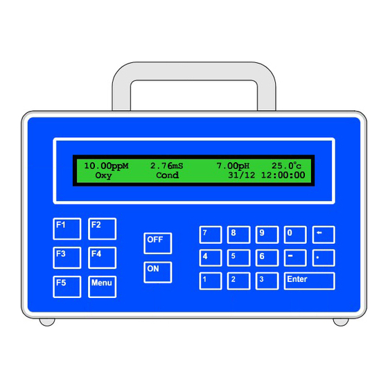
The introduction has a diagram and explanation of the display and controls of the 90-FL. It
also contains a full listing of all of the items that you should have received with unit. Please
take the time to read this section, as it explains some of items that are mentioned in subsequent
sections.
3. Main Section
The main section of the handbook provides complete details of the 90-FL, including operating
modes, calibration, troubleshooting, specifications, and warranty terms.
4. Appendices
Appendices containing background information and application notes are provided at the back
of this manual.
TPS Pty Ltd
4 Jamberoo Street
Springwood, Brisbane,
Australia, 4127
Phone
: (07) 32 900 400
International : 61 7 32 900 400
Fax
: (07) 3808 4871
International : 61 7 3808 4871
E-mail
:
tps@tps.com.au
Web Site
: www.tps.com.au
90-FL
Dissolved Oxygen,
Conductivity, TDS, pH,
Temperature Logger
Date
: 01-Feb-2001
Author : MS
Version : 6.0
Advertisement
Table of Contents
Troubleshooting

Related Manuals for TPS 90-FL


Summary of Contents for TPS 90-FL
- Page 1 Oxygen, Conductivity, TDS, pH and Temperature. Despite its impressive list of features, the 90-FL is a breeze to operate. This manual has been designed to help you get started, and also contains some handy application tips. If at any stage you require assistance, please contact either your local TPS representative or the TPS factory in Brisbane.
-
Page 2: Table Of Contents
Contents Introduction ............................3 1.1 90-FL Display and Controls......................3 1.2 90-FL Rear Panel Connectors ......................3 1.3 Menu and Function Keys ......................... 4 1.4 Numeric Keys..........................4 1.5 Enter Key ............................4 1.6 Delete Key ............................4 1.7 ON and OFF Keys ........................... 4 1.8 80 Character Display ........................ - Page 3 GLP Data Format ........................46 10.8 Importing Data into Microsoft Excel..................47 11. Setting the Clock ..........................49 12. Initialising the 90-FL ........................50 13. Instrument firmware version number ..................... 50 14. Battery Saver Function........................51 15. Moisture Protection ......................... 52 15.1...
-
Page 4: Introduction
1. Introduction 1.1 90-FL Display and Controls 1.2 90-FL Rear Panel Connectors... -
Page 5: Menu And Function Keys
Numeric Keypad. 1.7 ON and OFF Keys Press the relevant key to switch the 90-FL on and off as required. 1.8 80 Character Display 80 character alphanumeric display with user-friendly menu and context-sensitive help system. -
Page 6: Unpacking Information
1.9 Unpacking Information Before using your new 90-FL, please check that the following accessories have been included: Part No Standard Kit… 1. 90-FL Field Lab............. 126103 2. pH6.88 Buffer, 200mL........... 121306 3. pH4.00 Buffer, 200mL........... 121381 4. 2.76 mS/cm Conductivity Standard, 1 Litre.... 122305 5. -
Page 7: Specifications
1.10 Specifications 1.10.1 Dissolved Oxygen Range Resolution Accuracy 0 to 32.00 ppM 0.01 ppM ±0.2% of full scale 0 to 320.0 % Saturation % Saturation ±0.3 % Saturation 0 to 66.0 % Gaseous % Gaseous ±0.1 % Gaseous Note : Full scales are subject to sensor performance. Sensor Type...........Clark type polarographic sensor with in-built ATC. - Page 8 1.10.3 TDS Ranges Resolution Accuracy k=0.1 Sensor 0 to 1.000 ppM 0.001 ppM ±0.5% of full scale of 0 to 10.00 0.01 selected range at 25 0 to 100.0 0 to 1000 k=1.0 Sensor 0 to 10.00 0.01 ±0.5% of full scale of 0 to 100.0 selected range at 25...
- Page 9 1.10.5 Temperature Range Resolution Accuracy -30.0 to 110.0 ±0.2 Note : When using Conductivity/TDS sensor for Temperature readout, sensor is limited to 60 Sensor Type...........Silicon transistor built into tip of Conductivity/TDS sensor, or separate Temperature sensor if Conductivity / TDS sensor is not in use. Calibration ..........Automatic offset and span calibration Sensor Offset Range......-15.0 to 15.0 Sensor Span Range .......93 to 107 %...
-
Page 10: Fl Menu Structure
2. 90-FL Menu Structure A detailed breakdown of the menu system of the 90-FL is shown below. This diagram provides a quick reference for the menu functions available for the 90-FL. → → F1:Calibrate F1:Oxygen F2:Conductivity F2:TDS F3:pH F4:Temperature →... -
Page 11: Dissolved Oxygen Mode
A “∗” will not be removed from the display after a Zero Calibration. 5. Remove the sensor from the Zero solution, rinse well in distilled water and blot dry. The 90-FL will now prompt you to perform an AIR calibration. - Page 12 A “∗” in the display will be replaced by a decimal point after a successful air calibration. 3. The 90-FL is now calibrated and is ready for Dissolved Oxygen measurements. Rinse the Dissolved Oxygen sensor in distilled water and blot dry before placing it into unknown...
- Page 13 This span calibration provides an alternative to calibrating the Dissolved Oxygen sensor in air. It is only available when the 90-FL is in Salinity-corrected ppM mode. Please note that the normal AIR calibration (section 3.2.2) is still available for Salinity-corrected ppM mode.
-
Page 14: Dissolved Oxygen Calibration Notes
Zero=0.5% 2. If a Zero calibration has failed, the 90-FL will display the following message and the failed Zero value of the sensor. The unit will return to normal display mode with a “ ∗ ∗ ” in place of the decimal point in the Dissolved Oxygen reading. -
Page 15: Dissolved Oxygen Stirrer
3.5 Dissolved Oxygen Stirrer The 90-FL is equipped with a 4.5V DC output to power a stirrer for the Dissolved Oxygen sensor. This power output is suitable for the TPS submersible DO stirrer (part number 123306). 3.5.1 Enabling and Disabling the Dissolved Oxygen stirrer output →... -
Page 16: Conductivity Mode
→ → F2:Mode → → F3:Conductivity). 1. Select Conductivity Mode ( 2. The 90-FL now proceeds to Conductivity measurement mode. Note that a “ ∗ ∗ ” is shown in place of the decimal point until a successful calibration has been performed (see section 4.4). -
Page 17: Setting The Conductivity Sensor K Factor
4.3 Setting the Conductivity sensor k factor The 90-FL automatically recognises a k=10 sensor. If a k=10 sensor is being used, go directly to section 4.4. The 90-FL does not automatically recognise k=0.1 or k=1 sensors. When a k=0.1 or k=1 sensor is used, the 90-FL must be set to the correct k factor before use. -
Page 18: Conductivity Calibration
10. The 90-FL is now calibrated for Conductivity and is ready for use in this mode. Ensure that the sensor is immersed at least as deeply as per the diagram in step 7 for all sample... -
Page 19: Conductivity Calibration Notes
3. Conductivity and TDS calibration data is stored separately in memory. Ensure that the 90-FL has been correctly calibrated for the mode in which it will be used. The 90-FL does not require re-calibration when alternating between Conductivity and TDS modes, providing the instrument has been correctly calibrated for each mode on the k factor sensor to be used. -
Page 20: Tds Mode
→ → F2:Mode → → F4:TDS). 1. Select TDS Mode ( 2. The 90-FL now proceeds to TDS measurement mode. Note that a “ ∗ ∗ ” is shown in place of the decimal point until a successful calibration has been performed (see section 5.4). -
Page 21: Setting The Tds Sensor K Factor
5.3 Setting the TDS sensor k factor The 90-FL automatically recognises a k=10 sensor. If a k=10 sensor is being used, go directly to section 5.4. The 90-FL does not automatically recognise k=0.1 or k=1 sensors. When a k=0.1 or k=1 sensor is used, the 90-FL must be set to the correct k factor before use. -
Page 22: Tds Calibration
5.4 TDS Calibration Before attempting a TDS calibration, ensure that the 90-FL has been set up correctly according to sections 5.1 to 5.3. 1. Plug the TDS sensor into the Cond/Sal socket. 2. Rinse the TDS sensor in distilled water. Shake off as much water as possible. Blot the outside of the sensor dry. -
Page 23: Tds Calibration Notes
3. Conductivity and TDS calibration data is stored separately in memory. Ensure that the 90-FL has been correctly calibrated for the mode in which it will be used. The 90-FL does not require re-calibration when alternating between Conductivity and TDS modes, providing the instrument has been correctly calibrated for each mode on the k factor sensor to be used. -
Page 24: Ph Mode
6. pH Mode 6.1 Selecting the pH Buffer Set The 90-FL can be programmed to automatically recognise any of the following buffer sets during pH calibration. All pH values listed below are at 25 1. pH4.00, pH6.88, pH9.22 2. pH4.00, pH6.88, pH10.06 3. -
Page 25: Ph Calibration
The current pH reading is shown on the left. Note the “ ∗ ∗ ”, indicating that pH is currently not calibrated. Wait for this reading to stabilise before attempting to calibrate the 90-FL. The buffer that the 90-FL has attempted to recognise is also displayed with the correct value at the current temperature. -
Page 26: Ph Calibration Notes
Otherwise, enter an alternative buffer using the Numeric Keypad, and then press 10. The 90-FL is now pH calibrated and is ready for use in this mode. Discard the used samples of buffer. Rinse the pH and Conductivity/TDS or Temperature sensors in distilled water and blot them dry before placing them into unknown samples. -
Page 27: Ph Calibration Messages
Asymmetry Calibration Successful +0.10pH Asym 100% Slope 2. If a 1-point calibration has failed, the 90-FL will display the following message and the failed asymmetry value of the electrode. Calibrate Failed, 1.2pH Asymmetry Repeat Cal. or Initialise Calibration 3. -
Page 28: Temperature Mode
The 90-FL is able to take Temperature readings from the Conductivity/TDS sensor or a separate Temperature probe. Only one or the other can be connected at any one time. Ensure that the 90-FL has been calibrated on the correct sensor. -
Page 29: Temperature Calibration Notes
2 Point Calibration Failed, Span=200.0% 6. The 90-FL has an allowable span range of 93.0 to 107.0 %. If calibration fails due to the Span being outside these limits, then please consult the Troubleshooting guide (section 16.5) for... -
Page 30: Manual Temperature Setting
7.4 Manual Temperature Setting If a Conductivity/TDS or Temperature sensor is not connected, the temperature of the sample solution must be set manually for accurate ppM Dissolved Oxygen or pH measurements. A separate thermometer will be required for this. 1. Switch the meter on. 2. -
Page 31: Good Laboratory Practices (Glp)
8. Good Laboratory Practices (GLP) The 90-FL keeps a record of the date and time of the last calibrations for all parameters as part of GLP guidelines. 8.1 To recall GLP information on the display 1. Switch the meter on. - Page 32 GLP Display sequence, continued… TDS k=10.1 31/12/00 13:00 TDS Calibrated F2:Back F4:Next ↑ ↑ ↓ ↓ pH Asymmetry=0.10pH 31/12/00 13:30 pH Calibrated F2:Back F4:Next ↑ ↑ ↓ ↓ pH Slope= 99.0% 31/12/00 13:40 pH Calibrated F2:Back F4:Next ↑ ↑ ↓ ↓ Temperature Offset=1.0 31/12/00 14:30 Temp Probe Calibrated...
-
Page 33: Failed Calibration
RS232 port. 1. Switch the meter on. 2. Connect one end of the RS232 cable to the Charger socket of the 90-FL. The battery charger, optional battery adaptor, or optional solar panel may be connected to the in-line socket on the RS232 cable, if required. -
Page 34: Instrument Serial Number
8.4 Instrument Serial Number In case the serial number that is fitted to the rear of the 90-FL is removed or becomes illegible, it is also available on the 90-FL display. 1. The serial number is displayed at turn-on, for example…... -
Page 35: Datalogging
The Logger memory must be erased before changing the A & Data Input setting. To set the A & B Data Input function… → → F4:Setup → → F3:Set AB). The 90-FL will 1. Select the A & B setup menu ( prompt you to erase the Logger before proceeding, if any data is stored in memory. - Page 36 1. Alternatively, press to quit without recording the reading. 3. The 90-FL now proceeds to the B data entry screen… Data Recorded, Now Input B or Press Menu Enter Data B:0 Use the numeric keypad to key in up to four characters for the “B” data item. The decimal point is available.
- Page 37 1. Alternatively, press to quit without recording the reading. 3. The 90-FL now proceeds to the A data entry screen… Enter Data A:0 Data Recorded, Now Input A or Press Menu Use the numeric keypad to key in up to four characters for the “A” data item. The decimal point is available.
-
Page 38: Automatic Datalogging
• Unit is turned on continuously in this logging mode. • Dissolved Oxygen stirrer is switched on continuously in this logging mode (if Dissolved Oxygen stirrer output is enabled). The automatic datalogging parameters of the 90-FL must first be programmed, then logging can be started and stopped as required. - Page 39 2. If the Dissolved Oxygen stirrer is enabled, it is switched on for 40 seconds before the reading is recorded. 3. The 90-FL is switched on 3 minutes before the next reading is due to ensure that the Dissolved Oxygen sensor is fully polarised. The unit will therefore not automatically log any readings for...
- Page 40 00:00 00:00 00:00 00:00 00:00 00:00 Time 00:00 00:00 00:00 00:00 00:00 00:00 3. Use the Numeric Keypad to set the first time of the day at which the 90-FL will automatically log into memory. 4. Press to move to the next time of the day.
- Page 41 3. The 90-FL now prompts you to enter the sampling period in seconds. The current sampling period is displayed… Enter Sampling Period (secs) : 5 Use the Numeric Keypad to set the 90-FL to log a reading every 1 to 300 seconds. Press to save the new sampling period and move to setting the duration.
-
Page 42: Recalling Readings From The Logger
9.4 Recalling Readings from the Logger To recall records from the Logger onto the 90-FL display… → → F3:Logger) 1. Select the Logger menu ( 2. Select F1:Recall from the menu. Record number 1 is now displayed. The following example shows the display when the A & B Data Input function was switched off during logging…... -
Page 43: Erasing Records From The Logger
2. Connect the other end of the RS232 cable to an RS232 Printer, or to the COM1 or COM2 ports of a PC. 3. Ensure that the baud rate for the printer or PC and the 90-FL are the same. If necessary, alter the baud rate of the 90-FL (see section 10.1). -
Page 44: Rs232 Port
A TPS communication software package for Windows is optionally available (part number 130086). Once the data is saved to disk, the next problem is how to use it. The data sent by the 90-FL is ® ® formatted in fixed-width columns that can be imported by programs such as Microsoft Excel ®... - Page 45 (see section 10.7 for data format and hand-shaking). Enable Rate per Day or Time of ?J<cr> Starts automatic datalogging when the 90-FL is set up for Rate Day automatic datalogging per Day or Time of Day automatic datalogging (see sections 9.3.1 and 9.3.2).
-
Page 46: Data Format
10.6 Data Format Data is returned to the RS232 Port by the 90-FL in the following format. Please note that a “ • ” shown anywhere in this section denotes one space. dd/mm/yyyy•hh:mm:ss•LLLL•DDDDDuuu•CCCCCCCuuu•PPPPPuu•TTTTTuuLaaaaA•bbbbB where…. is the date, month and year data. -
Page 47: Glp Data Format
2. When requested by a PC with the ?D or ?R commands (section 10.5), the data is terminated with a carriage return. 3. When the data is sent by the 90-FL using the Print function (section 9.6) or the Instant Send function (section 10.2), the data ends with a carriage return and a line feed. -
Page 48: Importing Data Into Microsoft Excel
10.8 Importing Data into Microsoft Excel ® The following procedure details the method for importing a 90-FL text data file into Microsoft ® Excel ® ® and select File → Open 1. Start Microsoft Excel 2. In the “Files of type:” pull-down box, choose “Text Files (*prn; *.txt; *.csv)”. - Page 49 Press “Next >” after all the column breaks have been inserted. 6. Simply press “Finish” at step 3 of the Text Import Wizard. TPS recommends that the data format for each column be set once the data is in spreadsheet format.
-
Page 50: Setting The Clock
2. The 90-FL tests that a valid time of the day is entered. If an invalid time is entered (eg. 25:00), the 90-FL displays the message “Invalid Time”, then returns to the time setting screen so that the correct time can be entered. -
Page 51: Initialising The 90-Fl
12. Initialising the 90-FL If the calibration settings of the 90-FL exceed the allowable limits, the unit may need to be initialised to factory default values. This action may be required if a sensor is replaced or if the memory is corrupted. -
Page 52: Battery Saver Function
14. Battery Saver Function The 90-FL is equipped with a battery saver function. If no button has been pressed for 5 minutes or 1 hour , the unit beeps and flashes the display for 20 seconds and then shuts off. This function can also be switched off for continuous use. -
Page 53: Moisture Protection
15. Moisture Protection 15.1 Silica Gel Pack Due to the size of the 90-FL enclosure, it tends to expand in hot environments and contract in cold environments. This process can cause moist air to be drawn into the enclosure, which would then cause corrosion damage to the circuit. -
Page 54: Troubleshooting
16. Troubleshooting 16.1 General Errors Error Message Possible Causes Remedy Factory Calibration The EEPROM chip which The unit must be returned to TPS for Data Failure service. contains the factory calibration information has failed. EEPROM Write User calibration settings have Switch the meter OFF and switch back ON. -
Page 55: Dissolved Oxygen Troubleshooting
5% Ammonia poisoning. solution for 10 minutes. If cleaning is unsuccessful, return the sensor to the TPS factory for cleaning and service. Tarnished or scratched Gold Electrode has been chemically Return to the TPS factory for cleaning and cathode. -
Page 56: Conductivity / Tds Troubleshooting
Unit fails to calibrate, even Calibration settings outside of Check that the k factor is set correctly when with new probe. allowable limits due to previous not using a TPS k=10 sensor. failed calibration. Initialise the unit. See section 12. Unit attempts Span Sensor has Zero error. -
Page 57: Ph Troubleshooting
16.4 pH Troubleshooting Symptom Possible Causes Remedy Unit fails to calibrate, even Calibration settings outside of Switch the unit OFF and then back ON with new pH probe. allowable limits due to previous again and repeat calibration. failed calibration. Initialise the unit. See section 12. 1 Point calibration fails (pH 1. -
Page 58: Temperature Troubleshooting
Return Conductivity or Temperature sensor Temperature sensor, for repair, or replace sensor. whichever is being used. Displays manual 1. Faulty instrument socket. Return the instrument to the TPS factory for temperature setting (eg. service. 25.0 cM)when 2. Faulty Conductivity or... -
Page 59: Appendices
17. Appendices 17.1 Dissolved Oxygen 17.1.1 Dissolved Oxygen Sensor Fundamentals The electrode used is the amperometric type of Clark Electrode and is suitable for the measurement of oxygen pressures in the range 0 to 100 cm of mercury. While the probe actually reads partial pressure of oxygen, the circuit is calibrated to be read in percentage saturation or parts per million (Milligrams/litre). - Page 60 (a) Membrane correction is achieved AUTOMATICALLY ; (b) To provide the mass units (ppM) readout (so popular due to the Winkler process used in the past), the 90-FL Meter has Solubility Correction via an additional temperature sensor in the electrode ;...
- Page 61 17.1.6 Equilibrium Conditions Whilst Saline Water has a lower ppM than does Fresh Water, it does not mean it necessarily has less biologically available oxygen. Both have 100% Saturation (presuming no Chemical Oxygen Demand (C.O.D.), Biological Oxygen Demand (B.O.D.), etc.) because both are in partial pressure equilibrium with air.
-
Page 62: Conductivity/Tds
17.2.1 Care, Cleaning and Maintenance of Conductivity Sensors Care of Conductivity sensors The conductivity section of the sensor supplied with your 90-FL consists of two platinum plates that are plated with a layer of “platinum-black”. This is quite a soft layer and is required for stable, accurate measurements. - Page 63 Replatinising Conductivity Sensors There are several ways to replatinise Conductivity electrodes. 1. The simplest way is to return the electrode to the TPS factory. We can fully clean the electrode, replatinise it and test all aspects of its performance. 2. An automatic replatiniser is available from TPS, along with replatinising solution. This will plate the electrodes for the right amount of time at the correct current.
- Page 64 17.3 pH pH electrodes are generally combination electrodes, where the pH sensing membrane and the reference system are contained in a single body. The sensing membrane is the round or spear shaped bulb at the tip of the electrode. This produces a voltage that changes with the pH of the Solution.
- Page 65 17.3.2 Slope of a pH Electrode As mentioned above, a pH electrode produces 0 mV output at around 7.00 pH. As the pH goes up, an “ideal” pH electrode produces –59.16mV/pH unit at 25 C As the pH goes down, an ideal pH electrode produces +59.16mV/pH unit.
- Page 66 The following test can be performed to determine if the reference junction of a pH electrode is making adequate contact with the sample solution. 1. Calibrate the 90-FL, as per section 6.2. 2. Dilute 1 part of pH6.88 buffer with 9 parts of distilled water.
- Page 67 17.3.5 Determining if an instrument or electrode is faulty The following test can be performed to help determine if the 90-FL or the pH electrode is faulty. 1. Initialise the 90-FL (see section 12). 2. Disconnect the pH electrode from the pH connector.
-
Page 68: Warranty
TPS Pty. Ltd. has a fine reputation for prompt and efficient service. In just a few days, our factory service engineers and technicians will examine and repair your equipment to your full satisfaction.
Need help?
Do you have a question about the 90-FL and is the answer not in the manual?
Questions and answers