Table of Contents
Advertisement
Congratulations !
You have purchased the latest in Handheld, Waterproof pH-mV-
Temperature instrumentation. We trust that your new Aqua-pH will give
you many years of reliable service.
The Aqua-pH is a breeze to operate. This manual has been designed to
help you get started, and also contains some handy application tips. If at
any stage you require assistance, please contact either your local TPS
representative or the TPS factory in Brisbane.
The manual is divided into the following sections:
1. Table of Contents
Each major section of the handbook is clearly listed. Sub-sections
have also been included to enable you to find the information you
need at a glance.
2. Introduction
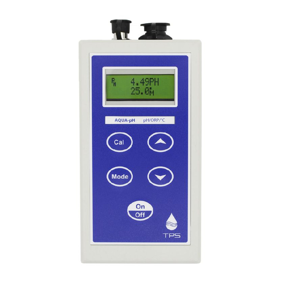
The introduction has a diagram and explanation of the display and
controls of the Aqua-pH. It also contains a full listing of all of the
items that you should have received with your Aqua-pH. Please take
the time to read this section, as it explains some of items that are
mentioned in subsequent sections.
3. Main Section
The main section of the handbook provides complete details of the
Aqua-pH, including operating modes, calibration, troubleshooting,
specifications, and warranty terms.
4. Appendices
Appendices containing background information and application notes
are provided at the back of this manual.
TPS Pty Ltd
4 Jamberoo Street
Springwood, Brisbane,
Australia, 4127
Phone
: (07) 32 900 400
International : 61 7 32 900 400
Fax
: (07) 3808 4871
International : 61 7 3808 4871
Email
: tps@tps.com.au
Web
: www.tps.com.au
Model Aqua-pH
pH-mV-Temp. Meter
Version
: 1.0
Date
: 19/02/2002
Author
: MS
Advertisement
Table of Contents
Troubleshooting

Subscribe to Our Youtube Channel
Related Manuals for TPS Aqua-pH


Summary of Contents for TPS Aqua-pH
- Page 1 2. Introduction The introduction has a diagram and explanation of the display and controls of the Aqua-pH. It also contains a full listing of all of the items that you should have received with your Aqua-pH. Please take the time to read this section, as it explains some of items that are mentioned in subsequent sections.
-
Page 2: Table Of Contents
Page 1 Contents Introduction ....................2 1.1 Aqua-pH Display and Controls................2 1.2 Unpacking Information ..................4 1.3 Specifications....................5 Operating Modes..................6 pH Calibration ..................7 3.1 Calibration ......................7 3.2 pH Calibration Notes ..................9 3.3 pH Calibration Messages................. 10 Millivolt Calibration ................ -
Page 3: Introduction
Page 2 1. Introduction 1.1 Aqua-pH Display and Controls... - Page 4 7. ° ± These keys toggle the Aqua-pH between Large Display mode and Dual Display mode. See section 2. NOTE: The digits in Large Display mode are made by combining the two rows of the display. This results in a small gap...
-
Page 5: Unpacking Information
Page 4 1.2 Unpacking Information Before using your new Aqua-pH, please check that the following accessories have been included: Part No 1. Aqua-pH pH-mV-Temperature Instrument ......121112 2. pH Sensor, Porous Teflon Double Junction, 1m ...... 121207 3. Temperature Sensor, Stainless Steel , 1m....... 121247 4. -
Page 6: Specifications
Page 5 1.3 Specifications Ranges Resolution Accuracy 0 to 14.00 pH 0.01 pH ±0.01 pH 0 to ±1500 mV 1 mV ±1 mV Temperature -10.0 to 120.0 ±0.2 Additional pH Specifications Temperature Compensation....Automatic, 0 to 50.0 Ω pH Input Impedance......>3 x 10 pH Asymmetry Range ......-1.00 to 1.00 pH pH Slope Range.........85.0 to 105.0% Auto pH Buffer Recognition....pH4.00, pH6.88, pH7.00 pH9.23,... -
Page 7: Operating Modes
Page 6 2. Operating Modes Press the key to select the desired operating mode. The sequence is shown in the following table… 7.00pH pH Mode 25.0 pH data is shown on the top line and Temperature data is shown on the bottom line. -
Page 8: Ph Calibration
Temperature sensor into the Temperature socket (this is the 6-pin plastic socket). If the Temperature sensor is not connected, then the Aqua-pH will use manual temperature compensation. Ensure that temperature has already been calibrated, or manually set (see sections 5.1 and 5.4). - Page 9 12. When the reading has stabilised, press and hold the key for 2 seconds to calibrate. The “ ∗ “ will now be replaced by a decimal point, if calibration was successful. 13. The Aqua-pH is calibrated for pH and is ready for use in this mode.
-
Page 10: Ph Calibration Notes
All calibration information is retained in memory when the Aqua-pH is switched off, even when the battery is removed. The Aqua-pH displays the value of the pH buffer that it has attempted to recognise at calibration. Ensure that the buffer value... -
Page 11: Ph Calibration Messages
100.0%. then: 1 point 6.88 Asym= 0.10pH Cal. OK Slope=100.0% If a 1-point calibration has failed, the Aqua-pH will display the following message, then the failed asymmetry value of the sensor. then: 1 point 6.88 Asym= 1.50pH Cal. Failed... -
Page 12: Millivolt Calibration
Page 11 4. Millivolt Calibration The mV section is factory calibrated. There is no user-calibration facility for this mode. -
Page 13: Temperature Calibration
Plug the Temperature sensor into the Temperature socket (this is the 6-pin plastic socket). If the Temperature sensor is not connected, then the Aqua-pH will use manual temperature compensation. In this case, refer to section 5.4 for details on setting manual temperature compensation values. -
Page 14: Calibration Notes
Temperature sensor is replaced or the meter is initialised. 5.3 Calibration Messages If a temperature calibration has been successfully performed, the Aqua-pH will display the offset value of the sensor. For example… Cal. OK Offset=1.0 If a temperature calibration has failed, the Aqua-pH will display the failed offset value of the sensor. -
Page 15: Selecting Buffers For Auto Buffer Recognition
Page 14 6. Selecting Buffers for Auto Buffer Recognition The Aqua-pH is factory set to automatically recognise pH4.00, pH6.88 and pH9.23 buffers. However, some users may prefer to use pH7.00 instead of pH6.88 and pH10.00 instead of pH9.23. The following procedure describes how to set which of these buffers are automatically recognised at calibration. -
Page 16: Battery Saver Function
Page 15 7. Battery Saver Function The Aqua-pH is equipped with a battery saver function. If no button has been pressed for five minutes, the unit beeps and flashes the display for 20 seconds, and then shuts off. This function can be disabled for continuous use. -
Page 17: Initialising The Aqua-Ph
Page 16 8. Initialising the Aqua-pH If the calibration settings of the Aqua-pH exceed the allowable limits, and the unit cannot be re-calibrated, then it may need to be initialised to factory default values. This action may be required if a sensor is replaced. -
Page 18: Troubleshooting
Possible Causes Remedy Message Factory The EEPROM chip which The unit must be returned to Cal. Fail contains the factory TPS for service. calibration information has failed. Handbook Memory User calibration settings Re-calibrate the instrument. Failed have been lost or corrupted. -
Page 19: Ph And Mv Troubleshooting
1. Incorrect primary buffer. Ensure that you are using fails (Slope is less the buffers which the than 85.0%). Aqua-pH has been set to automatically recognise (See section 6). 2. Glass bulb not clean. Clean glass bulb as per instructions supplied with the sensor. -
Page 20: Temperature Troubleshooting
Page 19 pH and mV Troubleshooting, continued... Unstable 1. Reference junction Clean reference junction, as readings. blocked. per instructions supplied with the sensor. 2. Glass bulb not clean. Clean glass bulb as per instructions supplied with the sensor. 3. Bubble in glass bulb. Flick the sensor to remove bubble. -
Page 21: Appendices
Page 20 10. Appendices 10.1 pH Sensor Fundamentals A combination pH sensor is two sensors in one. The sensing membrane is the round or spear shaped bulb at the tip of the sensor. This produces a voltage that changes with the pH of the solution. This voltage is measured with respect to the second part of the sensor, the reference section. - Page 22 Page 21 10.1.2 The Slope of a pH Sensor As mentioned above, a pH sensor produces 0 mV output at around 7.00 pH. As the pH goes up, an “ideal” pH sensor produces -59mV/pH unit at C As the pH goes down, an ideal pH sensor produces +59mV/pH unit.
- Page 23 Page 22 10.1.3 Temperature Compensation The slope of a pH sensor (section 10.1.2) is affected by temperature. This effect is compensated for either by using an Automatic Temperature Compensation (ATC) sensor or by entering the sample temperature manually. Figure 10-3 shows the slope of a pH sensor at various temperatures.
-
Page 24: Checking The Reference Junction Of A Ph Sensor
6. If the value obtained is still outside 7.06 +/-0.05 pH, then the sensor should be replaced. 10.3 Determining if an instrument or sensor is faulty The following test can be performed to help determine if the Aqua-pH or the pH sensor is faulty. 1. Initialise the Aqua-pH (see section 8). -
Page 25: Instrument Software Version Number
Page 24 10.4 Instrument software version number. If you need to phone or fax TPS for any further technical assistance, the version number of your Aqua-pH firmware may of benefit to us. Please obtain the version number before phoning or faxing. -
Page 26: Warranty
TPS Pty. Ltd. has a fine reputation for prompt and efficient service. In just a few days, our factory service engineers and technicians will examine and repair your equipment to your full satisfaction. - Page 27 Page 26 To obtain this service, please follow this procedure Return the instrument AND ALL SENSORS to TPS freight pre-paid and insured in its original packing or suitable equivalent. INSIST on a proof of delivery receipt from the carrier for your protection in the case of shipping claims for transit loss or damage.
Need help?
Do you have a question about the Aqua-pH and is the answer not in the manual?
Questions and answers