Table of Contents
Advertisement
Quick Links
Advertisement
Table of Contents

Subscribe to Our Youtube Channel
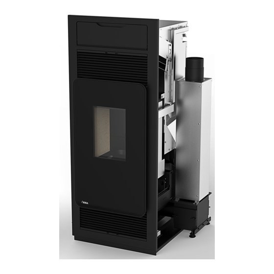
Summary of Contents for RIKA E15883
- Page 1 REVIVO 140 REVIVO 125 Assembly instructions...
-
Page 2: Explanations To Symbols
1x B18198 Flue collector Note 1x Z37505 Operating manuel REVIVO IT/EN t is strongly recommended to use the “RIKA installation kit E16223” for installation. Ask your local RIKA-dealer for it. 1x Z37509 Assembly instructions REVIVO IT/EN Supply range of control panel variants E15886 consisting of: Control panel / flush mounting cover / bracket / flush mounting frame... -
Page 3: Safety Clearances
Safety clearances Note In the inside space the pellet stove insert must be surrounded by incombustible materials. The following safety clearances must be observed in the inside space: b-e > 50mm, c-e > 50mm The following safety clearances must be observed from the front: a >... - Page 4 Dimensions Revivo 125 R auchr o hr 100mm R O - T L = 800mm F - T F - S R auchr o hr 100mm R O - S L = 177mm Dimensions Height [mm] Width [mm] Corpus depth [mm] H - P Pellet filling height...
- Page 5 Dimensions Revivo 140 R auchr o hr 100mm R O - T L = 800mm F - T F - S R auchr o hr 100mm R O - S L = 177mm Dimensions Height [mm] Width [mm] Corpus depth [mm] H - P Pellet filling height...
-
Page 6: Preparing The Electrical Connection
Preparing the warm-air tiled stove When adapting an existent warm-air tiled stove, all steps, covers, bases and similar, if any, must be removed. The recess must be flush with the floor. * according to installation variant (see page 3 - installation variants) Preparing the control panel variants Flush-mounted variant Wall-mounted variant... - Page 7 Remove the front cover. Mounting the lower base Remove the four fastening bolts and lift the flue collector off the base. Both retaining sheets have only been required for transport purposes. Put the base module in place inside the warm-air tiled stove. The front edge of the bottom plate must be flush with the front of the tiled stove.
-
Page 8: Flue Connection
Mounting the flue collector Connect the flue pipe to your flue (according to available connection possibilities). Be sure of leak tightness! Connect the upper base to the flue collector by means of the flue pipe (l=177mm) included in the shipment. Be sure of leak tightness! Attach the flue collector additionally to the upper base with two hex screws. -
Page 9: Adjusting The Front Panel
Remove the lifting handles and secure the stove module with the Lay the control panel cable alongside the lower base (behind the lock nuts included in the shipment (4x). cover), running it through the opening of the touch display. Secure the drag chain on the stove module with two hex screws. Be sure that the On/Off (I/O) switch is in OFF (O) position and connect the power cable to the mains supply. - Page 10 Securing the stove module Wall mounted installation of control panel Remove the lower convection grill using the opener included in the Connect the control panel cable to the touch display and fasten the shipment. wall mounting cover on the wall bracket using the magnets included in the shipment.
-
Page 11: Your Notes
Your notes:... - Page 12 RIKA Innovative Ofentechnik GmbH Müllerviertel 20 4563 Micheldorf / AUSTRIA Tel.: +43 (0)7582/686 - 41, Fax: -43 Technical and design changes, as well as typesetting and printing errors reserved E-Mail: verkauf@rika.at www.rika.at © 2017 | RIKA Innovative Ofentechnik GmbH...


Need help?
Do you have a question about the E15883 and is the answer not in the manual?
Questions and answers