Table of Contents
Advertisement
Available languages
Available languages
Quick Links
Important Safety Instructions 2
Installation
Digital Display
Using the Digital Display
Features
1111 W. 35th Street, Chicago, IL 60609 USA • www.tripplite.com/support
14-08-206-93338E.indb 1
Owner's Manual
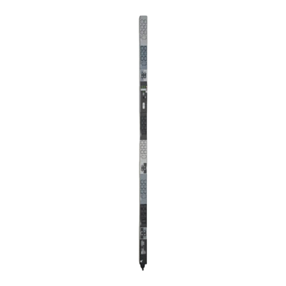
3-Phase Metered 0U
Power Distribution Unit
(Phase and Bank Measurements)
PDU3XMV6G32
(Series Number: AG-00BD)
12
Copyright © 2014 Tripp Lite. All rights reserved.
Service
3
Warranty and
Product Registration
5
Español
6
Français
Русский
1
13
14
15
29
43
10/9/2014 11:31:48 AM
Advertisement
Table of Contents

Related Manuals for Tripp Lite PDU3XMV6G32


Summary of Contents for Tripp Lite PDU3XMV6G32
- Page 1 Important Safety Instructions 2 Service Installation Warranty and Product Registration Digital Display Español Using the Digital Display Français Features Русский 1111 W. 35th Street, Chicago, IL 60609 USA • www.tripplite.com/support Copyright © 2014 Tripp Lite. All rights reserved. 14-08-206-93338E.indb 1 10/9/2014 11:31:48 AM...
- Page 2 Important Safety Instructions SAVE THESE INSTRUCTIONS This manual contains instructions and warnings that should be followed during the installation, operation, and storage of this product. Failure to heed these instructions and warnings may affect the product warranty. • The PDU provides the convenience of multiple outlets, but DOES NOT provide surge or line noise protection for connected equipment.
-
Page 3: Mounting The Pdu
Installation Mounting the PDU Note: The illustrations may differ somewhat from your PDU model. Regardless of configuration, the user must determine the fitness of hardware and procedures before mounting. The PDU and included hardware are designed for common rack and rack enclosure types and may not be appropriate for all applications. Exact mounting configurations may vary. -
Page 4: Connecting The Pdu
Installation Connecting the PDU The PDU3XMV6G32 is equipped with a 32A Red IEC 309 3P + N + E plug. Max Input Amps (Limited Input Output by Input Cord Voltage Voltage Cord Model Name Input Plug and Plug) Range Range... - Page 5 Digital Display 3-Digit Display: Shows measured or calculated values such as Amperage, Kilowatts, Voltage and Power Unbalance Percentage. Arrow Buttons: Scroll through indicated Input, Bank, Power, Load Balance and Display Brightness options using these buttons. A long press of the up or down arrow buttons allows the user to skip to the next sequential measurement category.
- Page 6 Digital Display Load Bank Receptacle Location and Display References PDU3XMV6G32 L1-N L2-N L3-N L1-N L2-N L3-N L1-N BANK 1 L1-N BANK 1 L2-N BANK 2 L3-N BANK 3 L3-N BANK 3 L1-N BANK 4 L2-N BANK 5 L2-N BANK 5...
- Page 7 Using the Digital Display Input Phase 2 Amps Volts* 4 0 0 i 5.5 Input Phase 3 Amps Volts* i 5.5 4 0 0 To Unbalanced Load Detect Unbalanced Load Detect (Measurement Category) Phase Imbalance % 14-08-206-93338E.indb 7 10/9/2014 11:31:52 AM...
- Page 8 Using the Digital Display Scrolling Through Load Banks and Options (Measurement Category) Scroll through the parameter display for each Load Bank using Mode and buttons. Amps Kilowatts Volts 1 0 .5 2. 1 8 2 0 8 Bank #2 Amps Kilowatts Volts 1 0 .5...
- Page 9 Using the Digital Display Press Mode button to toggle between options and data within a menu. A momentary press of the arrow buttons switches between menus. A long press skips between measurement categories. The scrolling pattern of the display is outlined below. Total Output Power (Measurement Category) Kilowatts i.2 3...
- Page 10 Using the Digital Display LED Brightness and Color Scheme (Configuration Category) Hold the Mode button for 3 seconds to scroll through each option. The number in the 2-digit display is defined as: 1=25%; 2=50%; 3=75%; 4=100% Bank Indicator LED Color Code Options (Configuration Category) Hold the Mode button for 3 seconds to switch between options.
- Page 11 Using the Digital Display BANK INDICATOR LED DEFINITIONS: LED Configuration LED Color Bank Status Description Bank power is absent Green Circuit breaker is on – Bank power is present Bank has exceeded 80% of its current rating – Yellow Standard Bank power is present Bank is below the Low Voltage threshold –...
- Page 12 Features Outlets: During normal operation, the outlets distribute AC power to connected equipment. Bank Status LED: Once the unit is powered on, each Bank Status LED will illuminate when the associated bank is ready to distribute live AC power. LED Color Bank Status Comments/Notes Green...
- Page 13 RJ-45 Configuration Port: For factory use only. Service Your Tripp Lite product is covered by the warranty described in this manual. A variety of Extended Warranty and On-Site Service Programs are also available from Tripp Lite. For more information on service, visit www.tripplite.com/support. Before returning your product for service, follow these steps: 1.
- Page 14 Service under this Warranty can only be obtained by your delivering or shipping the product (with all shipping or delivery charges prepaid) to: Tripp Lite, 1111 W. 35th Street, Chicago, IL 60609 USA. Seller will pay return shipping charges. Visit www.tripplite.com/support before sending any equipment back for repair.
-
Page 15: Español
Manual del propietario Unidad de Distribución de Energía Trifásica con Medidor Digital de 0U (Mediciones de Fase y Banco) PDU3XMV6G32 (Número de Serie: AG-00BD) Instrucciones Importantes Servicio de Seguridad Garantía Instalación English Pantalla Digital Français Usando la Pantalla Digital Русский... - Page 16 Instrucciones Importantes de Seguridad CONSERVE ESTAS INSTRUCCIONES Este manual contiene instrucciones y advertencias que deben seguirse durante la instalación, operación y almacenamiento de este producto. La omisión en la observancia de estas instrucciones y advertencias puede afectar la garantía del producto. •...
- Page 17 Instalación Instalación del PDU Nota: Las ilustraciones pueden diferir un poco de su modelo de PDU. Sin importar la configuración, el usuario debe determinar la adecuación de los accesorios y procedimientos antes de la instalación. El PDU y accesorios incluidos están diseñados para tipos comunes de racks y gabinetes y pueden no ser apropiados para todas las aplicaciones.
- Page 18 Instalación Conexión del PDU El PDU3XMV6G32 está equipado con una clavija IEC 309 de 3P + N + T, Roja de 32A. Amperes Máximos de Entrada (Limitado por el Rango de Rango de Nombre del Clavija de Cable y Clavija...
- Page 19 Pantalla Digital Pantalla de 3 Dígitos: Muestra los valores medidos o calculados como Amperaje, Kilowatts, Voltaje y Porcentaje de Desbalanceo de Potencia. Botones de Flecha: Usando estos botones, se desplaza a través de las opciones indicadas de Salida, Entrada, Banco, Potencia, Balance de Carga, Sensor Brillo de Pantalla. Una presión prolongada de los botones de flecha arriba o abajo permite al usuario saltar a la siguiente categoría de medición secuencial.
- Page 20 Pantalla Digital Ubicación del Receptáculo del Banco de Carga y Referencias de Pantalla PDU3XMV6G32 L1-N L2-N L3-N L1-N L2-N L3-N L1-N BANK 1 L1-N BANK 1 L2-N BANK 2 L3-N BANK 3 L3-N BANK 3 L1-N BANK 4 L2-N BANK 5...
- Page 21 Usando la Pantalla Digital Fase de Entrada 2 Amperes Volts* i 5.5 4 0 0 Fase de Entrada 3 Amperes Volts* i 5.5 4 0 0 Para Detectar Carga Detección de Carga Desbalanceada (Categoría de Medición) % de Desbalanceo de Fase 14-08-206-93338E.indb 21 10/9/2014 11:32:01 AM...
- Page 22 Usando la Pantalla Digital Desplazándose a Través de Bancos de Carga y Opciones (Categoría de Medición) Desplácese por la pantalla de parámetros para cada Banco de Carga usando los botones do modo (Mode) y Amperes Kilowatts Volts 1 0 .5 2.
- Page 23 Usando la Pantalla Digital Oprima el botón de modo (Mode) para cambiar entre opciones y datos dentro de un menú. Una presión momentánea de los botones de flecha cambia entre menús. Una presión prolongada salta entre categorías de mediciones. El patrón de desplazamiento en la pantalla se detalla a continuación.
- Page 24 Usando la Pantalla Digital Esquema de Brillo y Color del LED (Categoría de Configuración) Sostenga por 3 segundos el botón de modo (Mode) para desplazarse a través de cada opción. El número en la pantalla de 2 dígitos está definido como: 1=25%; 2=50%; 3=75%; 4=100% Opciones de Código de Color de Led Indicador de Tomacorriente (Categoría de Configuración) Sostenga el botón de modo (Mode) por 3 segundos para...
- Page 25 Usando la Pantalla Digital DEFINICIONES DE LED INDICADOR DE BANCO: Configuración Estado de Color de LED Descripción de LED Banco Apagado Apagado La energía del banco está faltante Verde Encendido El breaker está encendido – La energía del banco está presente El banco ha excedido el 80% de la especificación de la Amarillo Encendido...
- Page 26 Características Tomacorrientes: Durante la operación normal, los tomacorrientes distribuyen energía de CA al equipo conectado. LED de Estado de Banco: Una vez energizada la unidad, se encenderá cada LED de Estado de Banco cuando el banco asociado esté listo para distribuir energía activa de CA.
- Page 27 Puerto de Configuración RJ-45: Únicamente para uso en fábrica. Servicio Su producto Tripp Lite está cubierto por la garantía descrita en este manual. Tripp Lite también pone a su disposición una variedad de Garantías extendidas y Programas de servicio técnico en el sitio.
- Page 28 (con todos los cargos de envío o entrega prepagos) a: Tripp Lite; 1111 W. 35th Street; Chicago IL 60609; EE. UU. El vendedor abonará los cargos de envío de devolución.
-
Page 29: Français
Consignes de sécurité Entretien importantes Garantie Installation English Affichage numérique Español Utiliser l’affichage numérique 34 Русский Caractéristiques 1111 W. 35th Street, Chicago, IL 60609 USA • www.tripplite.com/support Copyright © 2014 Tripp Lite. Tous droits réservés. 14-08-206-93338E.indb 29 10/9/2014 11:32:06 AM... - Page 30 Consignes de sécurité importantes CONSERVEZ CES INSTRUCTIONS Ce manuel contient des instructions et des avertissements qui devraient être respectés pendant l’installation, l’utilisation et l’entreposage de ce produit. Le non-respect de ces instructions et de ces avertissements pourrait affecter la garantie du produit. •...
- Page 31 Installation Montage de l’unité de distribution d’énergie (PDU) Remarque : Les illustrations peuvent différer quelque peu de votre modèle d’unité de distribution d’énergie (PDU). Quelle que soit la configuration, l’utilisateur doit déterminer l’aptitude du matériel et des procédures avant de procéder au montage.
- Page 32 Installation Branchement de la PDU Le PDU3XMV6G32 est équipé d’un CEI 309 rouge de 32A 3P + N + T Ampérage d’entrée maximum (limité par le Gamme Gamme de Longueur cordon et la de tension tension de Nom du modèle Fiche d’entrée...
- Page 33 Affichage numérique Affichage à 3 chiffres : Affiche les valeurs mesurées telles que l’intensité de courant, kilowatt, tension et pourcentage de déséquilibre de puissance. Flèches de défilement : Parcourir les options indiquées Outlet (sortie), Input (entrée), Bank (rangée), Power (alimentation), Load Balance (équilibre de la charge), Sensor (capteur) et Display Brightness (affichage de la luminosité) au moyen de ces flèches.
- Page 34 Affichage numérique Emplacement de la prise de courant du banc d’essai et références de affichage PDU3XMV6G32 L1-N L2-N L3-N L1-N L2-N L3-N L1-N BANK 1 L1-N BANK 1 L2-N BANK 2 L3-N BANK 3 L3-N BANK 3 L1-N BANK 4...
- Page 35 Utiliser l’affichage numérique Phase d’entrée 2 Ampères Volts* 4 0 0 i 5.5 Phase d’entrée 3 Ampères Volts* i 5.5 4 0 0 Pour détecter les charges déséquilibrées Détection de charges déséquilibrées (catégorie de mesures) % de déséquilibre de la phase 14-08-206-93338E.indb 35 10/9/2014 11:32:08 AM...
- Page 36 Utiliser l’affichage numérique Parcourir les bancs d’essai et les options (catégories de mesures) Faire défiler l’affichage des paramètres pour chaque banc d’essai en utilisant les boutons Mode et . Ampères Kilowatts Volts 1 0 .5 2. 1 8 2 0 8 Banc #2 Ampères Kilowatts...
- Page 37 Utiliser l’affichage numérique Appuyer sur le bouton Mode pour basculer entre les options et les données sur un menu. Une brève pression des flèches de défilement permet de permuter entre les menus. Une longue pression permet de sauter entre les catégories de mesures. Le type de défilement de l’affichage est décrit ci-dessous.
- Page 38 Utiliser l’affichage numérique Intensité du voyant DEL et schéma de couleurs (catégorie de configuration) Maintenir le bouton Mode enfoncé pendant 3 secondes pour parcourir chaque option. Le nombre dans l’affichage à 2 chiffres est défini de la façon suivante : 1=25 %; 2=50 %; 3=75 %; 4=100 % Options du code de couleur du voyant DEL de sortie (catégorie de configuration) Maintenir le bouton Mode pendant 3 secondes pour passer d’une...
- Page 39 Utiliser l’affichage numérique DÉFINITIONS DES DEL POUR LES INDICATEURS DU BANC : Configuration du Couleur du États du banc Description voyant DEL voyant DEL Off (arrêt) Off (arrêt) Aucune alimentation au niveau du banc Le disjoncteur est sous tension – Vert On (marche) Alimentation au niveau du banc...
- Page 40 Caractéristiques Sorties : Lors du fonctionnement normal, les sorites distribuent une alimentation CA à l’équipement branché. DEL d’état du banc : Une fois que l’appareil est sous tension, chaque DEL d’état du banc s’allumera lorsque le banc lui étant associée est prêt à...
- Page 41 (direct, indirect, spécial ou fortuit) survenu au produit pendant le transport à Tripp Lite ou à un centre de service autorisé Tripp Lite est exclu de la garanti. Les produits expédiés à Tripp Lite ou à un centre de service autorisé doivent être prépayés. Inscrire le numéro RMA sur le paquet.
- Page 42 à sa discrétion. Vous pouvez obtenir un service selon cette garantie seulement en livrant ou en expédiant le produit (avec les frais d’expédition et de livraison prépayés) à : Tripp Lite, 1111 W. 35th Street, Chicago, IL 60609 USA. Le vendeur paiera les frais d’expédition de retour. Visitez www.tripplite.com/support avant de retourner de l’équipement pour réparation.
-
Page 43: Table Of Contents
технике безопасности Гарантийные обязательства 56 Установка English Цифровой дисплей Español Порядок использования Français цифрового дисплея Возможности 1111 W. 35th Street, Chicago, IL 60609 USA • www.tripplite.com/support Охраняется авторским правом © 2014 Tripp Lite. Перепечатка запрещается. 14-08-206-93338E.indb 43 10/9/2014 11:32:12 AM... -
Page 44: Важные Указания По
Важные указания по технике безопасности СОХРАНИТЕ НАСТОЯЩИЕ УКАЗАНИЯ В настоящем руководстве содержатся указания и предупреждения, которые необходимо соблюдать в процессе установки, эксплуатации и хранения данного изделия. Игнорирование этих указаний и предупреждений может привести к потере гарантии на изделие. • Блок распределения питания (PDU) удобно оснащен несколькими розетками, но НЕ обеспечивает... -
Page 45: Установка
Установка Монтаж PDU Примечание. Устройство, изображенное на иллюстрациях, может несколько отличаться от вашей модели PDU. Независимо от конфигурации, пользователь должен установить пригодность оснастки и предполагаемых процедур до начала монтажа. Блок распределения питания (PDU) и входящая в его комплект оснастка предназначены для обычных типов шкафов и могут не подходить для всех целей применения. Установочные конфигурации... - Page 46 Установка Подключение PDU Модель PDU3XMV6G32 оснащена разъемом типа IEC 309 3P + N + E (3 фазы + нейтраль + земля) красного цвета на 32 A Макс. входной ток в амперах (ограничивается сечениями Диапазон Диапазон Наименование входного шнура входных выходных...
-
Page 47: Цифровой Дисплей
Цифровой дисплей 3-разрядный дисплей: отображает измеренные и расчетные значения, такие как ток в амперах, мощность в киловаттах, напряжение в вольтах и дисбаланс мощности в процентах. Кнопки со стрелками: эти кнопки используются для переключения между следующими опциями: Outlet (Розетка), Input (Вход), Bank (Группа), Power (Питание), Load Balance (Баланс нагрузок), Sensor (Датчик) и... -
Page 48: Порядок Использования
Цифровой дисплей Расположение розеток по группам нагрузок и Сообщения на дисплее PDU3XMV6G32 L1-N L2-N L3-N L1-N L2-N L3-N L1-N BANK 1 L1-N BANK 1 L2-N BANK 2 L3-N BANK 3 L3-N BANK 3 L1-N BANK 4 L2-N BANK 5 L2-N BANK 5... - Page 49 Порядок использования цифрового дисплея Входная фаза 2 Амперы Вольты* i 5.5 4 0 0 Входная фаза 3 Амперы Вольты* i 5.5 4 0 0 К определению несбалансированной нагрузки Определение несбалансированной нагрузки (измерительная категория) Фазовый дисбаланс (%) 14-08-206-93338E.indb 49 10/9/2014 11:32:15 AM...
- Page 50 Порядок использования цифрового дисплея Прокрутка групп нагрузок и опций (измерительная категория) Прокручивайте отображаемые параметры для каждой группы потребителей с помощью кнопки выбора режима (MODE) и кнопки . Амперы Киловатты Вольты 1 0 .5 2. 1 8 2 0 8 Группы #2 Амперы...
- Page 51 Порядок использования цифрового дисплея Для переключения между опциями и данными внутри какого-либо меню нажмите кнопку выбора режима (MODE). При кратковременном нажатии кнопок со стрелками производится переключение между меню. При длительном нажатии производится переключение между измерительными категориями. Порядок прокрутки дисплея приведен ниже. Суммарная...
- Page 52 Порядок использования цифрового дисплея Яркость и цветовая маркировка светодиодных индикаторов (конфигурационная категория) Для прокрутки каждой опции удерживайте кнопку выбора режима (MODE) нажатой в течение 3 секунд. Цифра, отображаемая на 2-разрядном дисплее, означает следующее: 1=25%; 2=50%; 3=75%; 4=100% Опции цветовой маркировки светодиодных индикаторов розеток (конфигурационная...
- Page 53 Порядок использования цифрового дисплея ПОКАЗАНИЯ СВЕТОДИОДНЫХ ИНДИКАТОРОВ ГРУППА: Конфигурация светодиодных Группы индикаторов Цвет индикатора Статус Описание Отключен Отключен Питание группы отсутствует Автоматический выключатель в положении “вкл.” – Зеленый Включен Питание группы присутствует Ток через группы питание превысил 80% от Желтый Включен...
-
Page 54: Возможности
Возможности Розетки: в штатном режиме работы розетки распределяют мощность переменного тока между подключенными к ним элементами оборудования. Светодиодный индикатор статуса группы: при включении питания устройства каждый из светодиодных индикаторов статуса группы загорается в момент готовности соответствующей группы к распределению питания переменного тока. Цвет... -
Page 55: Техническое Обслуживание
Конфигурационный порт RJ-45: Только для промышленного применения. Техническое обслуживание На продукцию компании Tripp Lite распространяется гарантия, описанная в данном руководстве. Также доступны различные программы продлеваемой гарантии и обследования на объекте от компании Tripp Lite. Для получения более подробной информации о сервисном обслуживании... -
Page 56: Гарантийные Обязательства
Идентификационные номера, свидетельствующие о соответствии нормативным требованиям С целью идентификации, а также сертификации соответствия нормативным требованиям, приобретенному Вами изделию компании Tripp Lite присвоен уникальный серийный номер. Серийный номер, вместе со всей необходимой информацией и маркировками об одобрении, указан на ярлыке изготовителя, прикрепленном к...
Need help?
Do you have a question about the PDU3XMV6G32 and is the answer not in the manual?
Questions and answers