Daikin AZAS71M2V1B Installer's Reference Manual
Sky air active-series
Hide thumbs
Also See for AZAS71M2V1B:
- Installation manual (24 pages) ,
- Installer's reference manual (32 pages)

Related Manuals for Daikin AZAS71M2V1B


Summary of Contents for Daikin AZAS71M2V1B
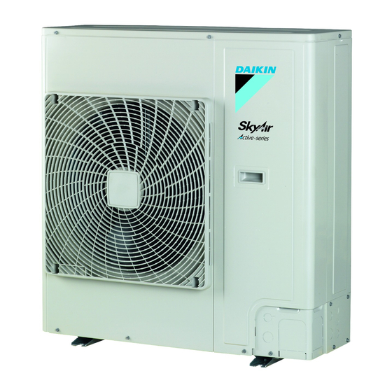
- Page 1 Installer reference guide Sky Air Active-series AZAS71M2V1B AZAS100M7V1B AZAS125M7V1B AZAS140M7V1B AZAS100M7Y1B Installer reference guide AZAS125M7Y1B English Sky Air Active-series AZAS140M7Y1B...
-
Page 2: Table Of Contents
Table of contents Charging refrigerant ..............17 Table of contents 6.6.1 About charging refrigerant ........... 17 6.6.2 About the refrigerant ............ 18 6.6.3 Precautions when charging refrigerant ......18 6.6.4 To determine the complete recharge amount ....18 1 General safety precautions 6.6.5 Charging refrigerant: Setup.......... -
Page 3: Meaning Of Warnings And Symbols
(on top of the waves. Electromagnetic waves may disturb the control system, instructions described in the Daikin documentation). and cause malfunction of the equipment. ▪ In places where there is a risk of fire due to the leakage of... - Page 4 ▪ Joints made in installation between parts of refrigerant system shall be accessible for maintenance purposes. WARNING Make sure installation, servicing, maintenance and repair comply with instructions from Daikin and with applicable legislation (for example national gas regulation) and are executed only by authorised persons. Installation space requirements NOTICE ▪...
-
Page 5: Refrigerant
1 General safety precautions Ceiling-mounted Wall-mounted Floor-standing DANGER: RISK OF EXPLOSION unit unit unit Pump down – Refrigerant leakage. If you want to pump m (kg) m (kg) m (kg) down the system, and there is a leakage in the refrigerant <1.224 —... -
Page 6: Brine
1 General safety precautions CAUTION WARNING When the refrigerant charging procedure is done or when ▪ ONLY use copper wires. pausing, close valve refrigerant tank ▪ Make sure the field wiring complies with the applicable immediately. If the valve is not closed immediately, legislation. -
Page 7: About The Documentation
Technical engineering data ▪ A subset of the latest technical data is available on the regional Daikin website (publicly accessible). ▪ The full set of latest technical data is available on the Daikin extranet (authentication required). Installer reference guide at a... -
Page 8: To Remove The Accessories From The Outdoor Unit
4 About the units and options 3.2.3 To remove the accessories from the Code Explanation outdoor unit Power supply: 1~, 220~240 V, 50 Hz Power supply: 3N~, 380~415 V, 50 Hz 1× 1× 2× European market Minor model change indication INFORMATION This unit is not intended for use in high humidity, low ambient temperature regions. - Page 9 5 Preparation NOTICE Install the outdoor unit away from direct sea winds. The equipment described in this manual may cause Example: Behind the building. electronic noise generated from radio-frequency energy. The equipment complies to specifications that are designed to provide reasonable protection against such interference.
-
Page 10: Additional Installation Site Requirements Of The Outdoor Unit In Cold Climates
5 Preparation 5.2.2 Additional installation site requirements of the outdoor unit in cold climates Protect the outdoor unit against direct snowfall and take care that the outdoor unit is NEVER snowed up. Requirement Limit 1 Minimum total one‑way piping Limit≤L1 5 m length 2 Maximum total one‑way piping... -
Page 11: Installation
6 Installation WARNING ▪ All wiring must be performed by an authorised electrician and must comply with the applicable legislation. ▪ Make electrical connections to the fixed wiring. 45°~90° ▪ All components procured on the site and all electrical construction must comply with... -
Page 12: To Install The Outdoor Unit
6 Installation ▪ If you install the unit on a frame, install a waterproof plate within 150 mm of the bottom side of the unit in order to prevent the invasion of water in the unit and to avoid the drain water dripping (see the following illustration). -
Page 13: Connecting The Refrigerant Piping
6 Installation 3 Insert a rubber sheet between the cables and the outdoor unit NOTICE to prevent the cable from scratching the paint (field supply). Take the following precautions on refrigerant piping into 4 Attach the cable’s ends. Tighten those ends. account: ▪... -
Page 14: Pipe Bending Guidelines
6 Installation Piping size Tightening Flare Flare shape (mm) torque (N•m) dimensions (A) (mm) (mm) 90° ±2 Ø9.5 33~39 12.8~13.2 Ø15.9 63~75 19.3~19.7 Refrigerant piping R=0.4~0.8 Part to be brazed Taping Manual valve Pressure-reducing valve 6.4.4 Pipe bending guidelines Nitrogen ▪... -
Page 15: To Connect The Refrigerant Piping To The Outdoor Unit
6 Installation 3 If you have chosen the downwards piping route: To open/close the stop valve ▪ Drill (a, 4×) and remove the knockout hole (b). 1 Remove the stop valve cover. ▪ Cut out the slits (c) with a metal saw. 2 Insert a hexagon wrench (liquid side: 4 ... -
Page 16: Checking The Refrigerant Piping
6 Installation NOTICE 6.5.2 Precautions when checking the refrigerant piping Do not block the air vents. This could affect air circulation inside the unit. INFORMATION Also read the precautions and requirements in the following chapters: ▪ General safety precautions ▪ Preparation NOTICE Use a 2-stage vacuum pump with a non-return valve that can evacuate to a gauge pressure of −... -
Page 17: To Perform Vacuum Drying
6 Installation Typical workflow – Charging additional refrigerant typically consists 6.5.5 To perform vacuum drying of the following stages: NOTICE 1 Determining if and how much you have to charge additionally. ▪ Connect the vacuum pump to both the service port of 2 If necessary, charging additional refrigerant. -
Page 18: About The Refrigerant
6 Installation WARNING The refrigerant inside the unit is mildly flammable, but normally does not leak. If the refrigerant leaks in the room and comes in contact with fire from a burner, a heater, or a cooker, this may result in fire, or the formation of a harmful gas. -
Page 19: To Completely Recharge Refrigerant
Connecting the main power supply. ▪ When charging refrigerant, always use protective gloves and safety glasses. 6.7.2 About electrical compliance CAUTION AZAS71M2V1B + AZAS100~140M7V1B To avoid compressor breakdown, do NOT charge more Equipment complying with EN/IEC 61000‑3‑12 (European/ than the specified amount of refrigerant. -
Page 20: Guidelines When Connecting The Electrical Wiring
6 Installation 6.7.4 Guidelines when connecting the electrical Wire type Installation method wiring Stranded conductor wire with round Keep the following in mind: crimp-style terminal ▪ If stranded conductor wires are used, install a round crimp-style terminal on the end of the wire. Place the round crimp-style terminal on the wire up to the covered part and fasten the terminal a Terminal with the appropriate tool. -
Page 21: Finishing The Outdoor Unit Installation
6 Installation Routing through Choose one of the 3 possibilities: 1~50 Hz 3N~50 Hz the frame 220-240 V 380-415 V L1 L2 L3 L1 L2 L3 a Power supply cable b Interconnection cable Connecting to the When cables are routed from the unit, a frame protection sleeve for the conduits (PG insertions) can be inserted at the knockout... -
Page 22: To Close The Outdoor Unit
7 Commissioning 6.8.2 To close the outdoor unit Precautions when commissioning INFORMATION During the first running period of the unit, the required power may be higher than stated on the nameplate of the unit. This phenomenon is caused by the compressor, that needs a continuous run time of 50 ... -
Page 23: To Perform A Test Run
7 Commissioning The fuses or locally installed protection devices are Action Result installed according to this document, and have not been Select Test Operation. Service Settings bypassed. Test Operation Maintenance Contact Field Settings The power supply voltage matches the voltage on the Demand identification label of the unit. -
Page 24: Hand-Over To The User
8 Hand-over to the user Error code Possible cause NOTICE Nothing displayed ▪ The wiring is disconnected or there is a In Europe, the greenhouse gas emissions of the total wiring error (between power supply and refrigerant charge in the system (expressed as tonnes (the currently set outdoor unit, between outdoor unit and -equivalent) is used to determine the maintenance... -
Page 25: Checklist For Yearly Maintenance Of The Outdoor Unit
10 Troubleshooting 6 Never directly connect power supply cables to compressors (U, 11.1 Overview: Disposal V, W). This can result in a compressor burnout. Typical workflow Checklist for yearly maintenance Disposing of the system typically consists of the following stages: of the outdoor unit Pumping down the system. -
Page 26: 12 Technical Data
12 Technical data Technical data A subset of the latest technical data is available on the regional Daikin website (publicly accessible). The full set of latest technical data is available on the Daikin extranet (authentication required). 12.1 Overview: Technical data This chapter contains information about: •... -
Page 27: Piping Diagram: Outdoor Unit
12 Technical data Multiple rows of units ( b (mm) ≥100 ≤½H b≥250 ≥100 ½H <H ≤H b≥300 ≥100 ≥100 >H ≥100 ≥2000 ≥3000 ≥200 ≥250 ≥1000 ≥250 ≥1500 Stacked units (max. 2 levels) ( ≥100 ≥100 ≥500 ≥500 ≥300 ≥1000 ≥100 ≥100... -
Page 28: Wiring Diagram: Outdoor Unit
12 Technical data Compressor Flare connection Field piping (liquid: Ø9.5 flare connection) Distributor Field piping (gas: Ø15.9 flare connection) Liquid receiver Heating Cooling 12.4 Wiring diagram: Outdoor unit The wiring diagram is delivered with the unit, located at the inside of (4) Legend the service cover. -
Page 29: Glossary
13 Glossary Field supply TC1 (A1P) (V1 only) Signal transmission circuit Equipment not made by Daikin that can be combined with TC (A1P) (Y1 only) Signal transmission circuit product according instructions V1 (V1 only) Varistor accompanying documentation. V1D (A1P) (V1 only) - Page 32 4P486048-1A 2017.08...
Need help?
Do you have a question about the AZAS71M2V1B and is the answer not in the manual?
Questions and answers