Table of Contents
Advertisement
Advertisement
Table of Contents

Related Manuals for Sercomm RC8111


Summary of Contents for Sercomm RC8111
- Page 1 Wireless Network HD Camera User’s Guide...
-
Page 2: Table Of Contents
Table of Contents CHAPTER 1 INTRODUCTION....................1 Overview ..........................1 Physical Details - Wireless Network HD Camera ............4 Package Contents ......................6 CHAPTER 2 BASIC SETUP ....................7 System Requirements ......................7 Installation - Wireless Network HD Camera ..............7 CHAPTER 3 VIEWING LIVE VIDEO .................. - Page 3 Copyright 2014. All Rights Reserved. Document Version: 1.0 All trademarks and trade names are the properties of their respective owners.
-
Page 4: Chapter 1 Introduction
Chapter 1 Introduction This Chapter provides details of the Wireless Network HD Camera's features, components and capabilities. Overview The Wireless Network HD Camera has an Integrated Microcomputer and a high quality Mega Pixel Omni Vision CMOS Sensor, enabling it to display high quality live streaming video over your wired LAN, the Internet, and for the Wireless Network HD Camera, an 802.11N Wireless LAN. -
Page 5: Internet Features
Stream Live Video to Multiple Users. The video encoder and HTTP server built into the camera generate a ready-to-view video stream. Just connect to the camera using your Web browser to view live video. Suitable for Home, Business or Public Facilities . - Page 6 WEP Support . Full WEP support (64/128 Bit) on the Wireless interface is provided. WPA/WPA2 Support . The WPA Personal/WPA2 Personal standard is also supported, allowing advanced encryption of wireless data. WPS Support. WPS (Wi-Fi Protected Setup) can simplify the process of connecting any device to the wireless network by using the push button configuration (PBC) on the Wireless Network HD Camera, or entering a PIN code if there's no button.
-
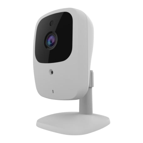
Page 7: Physical Details - Wireless Network Hd Camera
Physical Details - Wireless Network HD Camera Front - Wireless Network HD Camera Figure 2: Front Panel This is hardware sensor to detect LUX. Light Sensor No physical adjustment is required or possible for the lens, but you Lens should ensure that the lens cover remain clean. The image quality is degraded if the lens cover is dirty or smudged. - Page 8 LAN port Use the provided RJ-45 cable to connect your Wireless Network HD Camera to a 10/100BaseT hub or switch. Note: Plugging in the LAN cable will disable the Wireless interface. Only 1 interface can be active at any time. ...
-
Page 9: Package Contents
Package Contents The following items should be included: If any of these items are damaged or missing, please contact your dealer immediately. 1. Wireless Network HD Camera x 1 2. Stand x 1 3. DC power adapter x 1... -
Page 10: Chapter 2 Basic Setup
Chapter 2 Basic Setup This Chapter provides details of installing and configuring the Wireless Network HD Camera. System Requirements To use the wired LAN interface, a standard 10/100BaseT hub or switch and network cable is required. To use the Wireless interface on the wireless model, other Wireless devices must be compliant with the IEEE802.11b, IEEE802.11g or IEEE 802.11n specifications. - Page 11 3. Power Up Connect the supplied 12Vpower adapter to the Wireless Network HD Camera and power up. Use only the power adapter provided. Using a different one may cause hardware damage. 4. Check the LEDs The Power LED will turn on briefly, then start blinking. It will blink during startup, which takes 55 to 57 seconds.
-
Page 12: Chapter 3 Viewing Live Video
Chapter 3 Viewing Live Video This Chapter provides basic information about viewing live video. Overview This Chapter has details of viewing live video using Internet Explorer. But many other powerful features and options are available: The camera administrator can also adjust the Video Stream, and restrict access to the video stream to known users by requiring viewers to supply a username and password. - Page 13 Figure 4: Home Screen 4. Click View Video. 5. If the Administrator has restricted access to known users, you will then be prompted for a username and password. Enter the name and password assigned to you by the Wireless Network HD Camera administrator.
-
Page 14: Connecting To A Camera Via The Internet
Connecting to a Camera via the Internet You can NOT connect to a camera via the Internet unless the camera Administrator has configured both the camera and the Internet Gateway/Router used by the camera. See Making Video available from the Internet in Chapter 4 - Advanced Viewing Setup for details of the required configuration. - Page 15 5. Click View Video. 6. If the Administrator has restricted access to known users, you will then be prompted for a username and password. Enter the name and password assigned to you by the Wireless Network HD Camera administrator. 7. The first time you connect to the camera, you will be prompted to install decoders. Choose "I accept the terms of the license agreement"...
-
Page 16: Viewing Live Video
Viewing Live Video After installing the decoders, you will be able to view the live video stream in its own window, as shown below. Figure 6: View Video Screen There are a number of options available on this screen, accessed by select list, button or icon. See the table below for details. -
Page 17: General Options
General Options These options are always available, regardless of the type of camera you are connected to. Streaming. Use this drop-down list to select the desired streaming. Full Size. When using high-resolution mode (1280*720), click this button to see the full size of the image. Select the desired option from the drop-down list. -
Page 18: Chapter 4 Advanced Viewing Setup
Chapter 4 Advanced Viewing Setup This Chapter provides information about the optional settings and features for viewing video via the Wireless Network HD Camera. This Chapter is for the Camera Administrator only. Introduction This chapter describes some additional settings and options for viewing live Video: ... - Page 19 Select the default channel for streaming from the drop-down list. Default Streaming Channel Streaming 1 Settings Select the desired format from the list. Video Format Resolution Select the desired video resolution format. Constant Bit Rate: Select the desired bit rate. The default is set Video Quality to 4.0 Mbps.
-
Page 20: Controlling User Access To The Video Stream
Controlling User Access to the Video Stream By default, anyone can connect to the Wireless Network HD Camera and view live Video at any time. If desired, you can limit access to scheduled times, and also restrict access to known users. To Control User Access to Live Video: 1. -
Page 21: Making Video Available From The Internet
Making Video available from the Internet If your LAN is connected to the Internet, typically by a Broadband Gateway/Router and Broadband modem, you can make the Wireless Network HD Camera available via the Internet. You will need to configure your Router or Gateway to allow connections from the Internet to the camera. - Page 22 Wireless Network HD Camera Setup The Wireless Network HD Camera configuration does NOT have to be changed, unless: You wish to change the port number from the default value. HTTPS Port Configuration Normally, HTTP (Web) connections use port 80. Since the Wireless Network HD Camera uses HTTP, but port 80 is likely to be used by a Web Server, you can use a different port for the Wireless Network HD Camera.
-
Page 23: Viewing Live Video Via The Internet
Viewing Live Video via the Internet Clients (viewers) will also need a broadband connection; dial-up connections are NOT recommended. Viewing Live Video Using your Web Browser If using your Web browser, you need to know the Internet IP address (or the Domain name) of the camera's Router/Gateway, and the correct port number. -
Page 24: Motion Detection Alerts
Motion Detection Alerts The Motion Detection feature can generate an Alert when motion is detected. The Wireless Network HD Camera will compare consecutive frames to detect changes caused by the movement of large objects. But the motion detector can also be triggered by: ... -
Page 25: Chapter 5 Web-Based Management
Chapter 5 Web-based Management This Chapter provides Setup details of the Wireless Network HD Camera’s Web-based Interface. This Chapter is for the Camera Administrator only. Introduction The Wireless Network HD Camera can be configured using your Web Browser. The Wireless Network HD Camera must have an IP address which is compatible with your PC. -
Page 26: Welcome Screen
Welcome Screen When you connect, the following screen will be displayed. Figure 13: Welcome Screen The menu options available from this screen are: View Video - View live Video using your Web Browser. See Chapter 3 - Viewing Live Video for details. -
Page 27: Administration Menu
Administration Menu Clicking on Administration on the menu provides access to all the settings for the Wireless Network HD Camera. The Administration menu contains the following options: Setup System Network Wireless I/O Port Video & Audio ... -
Page 28: System Screen
System Screen After clicking Administration on the main menu, or selecting System on the Administration menu, you will see a screen like the example below. Figure 14: System Screen Data - System Screen System Settings Device ID This displays the ID for the Wireless Network HD Camera. Enter the desired name for the Wireless Network HD Camera. - Page 29 Time Zone Choose the Time Zone for your location from the drop-down list. If your location is currently using Daylight Saving, please enable the Adjust for daylight saving checkbox. Enable or disable the Time Server feature as required. Network Time Protocol If Enabled, the Wireless Network HD Camera will contact a Network Time Server at regular intervals and update its internal timer.
-
Page 30: Network Screen
Network Screen This screen is displayed when the Network option is clicked. Figure 15: Network Screen Data - Network Screen Network Internet Connection There are 3 connection types: Type Obtain Address Automatically (DHCP): If selected, the Wireless Network HD Camera will obtain its IP address and related information from a DHCP Server. - Page 31 Primary DNS server - Use the same value as PCs on your LAN. Use the following Normally, your ISP will provide this address. DNS server address Secondary DNS server - This is optional. If entered, this DNS will be used if the Primary DNS does not respond. This sets the port number for HTTP/HTTPS connections to the HTTP/HTTPS Camera, whether for administration or viewing video.
- Page 32 If enabled, the throughput level (for Video and Audio) is Enable QoS Mode guaranteed through QoS (Quality of Service). Enter the desired value of Differentiated Services Code Point DSCP (DSCP). The value must be between 0 and 63.
-
Page 33: Wireless Screen
Wireless Screen This screen is displayed when the Wireless menu option is clicked. Figure 16: Wireless Screen Data - Wireless Screen Wireless Network Click the "Site Survey" button and select from a list of available Site Survey APs. WSC PIN Code It displays the WSC PIN code number for the camera. - Page 34 Security Select the desired option, and then enter the settings for the selected Security System method: Disabled - No security is used. Anyone using the correct SSID can connect to your network. This is default. WEP - The 802.11b standard. Data is encrypted before transmission, but the encryption system is not very strong.
-
Page 35: Streamings
Streamings This screen is displayed when the Streamings menu option is clicked. If you want to view streaming via the cell phone: 1. Cell phone should be supported by 3GPP protocol. 2. Enter 554 for RTSP port number in the Network screen. 3. - Page 36 Data - Streamings Screen Select the default channel for streaming from the drop-down list. Default Streaming Channel Streaming 1 Settings Select the desired format from the list. Video Format Resolution Select the desired video resolution format. Constant Bit Rate: Select the desired bit rate. The default is set Video Quality to 2.0 Mbps.
-
Page 37: Video & Audio Screen
Video & Audio Screen This screen is displayed when the Video & Audio menu option is clicked. Figure 18: Video & Audio Screen Data - Video & Audio Screen Basic Video Adjustment Select the power line frequency (50Hz or 60Hz) used in your region, Power Line Frequency to improve the picture quality under florescent lighting. - Page 38 IRLED Luminance Select the desired lightness for the IR LED. Options Enable Microphone Enable audio by checking this checkbox. Using Audio will increase the bandwidth requirements slightly. Select the desired audio type. Audio Type Flip This setting will have the image swapped top-to-bottom. This setting will have the image swapped left-to-right.
-
Page 39: Video Access Screen
Video Access Screen This screen is displayed when the Video Access option is clicked. Figure 19: Video Access Screen Data - Video Access Screen User Access If disabled (default) - No login required. Users do not have to Enable Security provide a username and password when they connect to the Checking camera for viewing video. - Page 40 Add New Schedule Choose the desired option for the period. Start Time Enter the start time using a 24 hr clock. Enter the end time using a 24 hr clock. End Time Click this button to add a new period. Clear Use this button to clear the input fields.
-
Page 41: User Database Screen
User Database Screen This screen is displayed when the User Database option is clicked. Figure 20: User Database Screen Data - User Database Screen Existing Users This displays all users you have entered into the User database. If User List you have not entered any users, this list will be empty. -
Page 42: Pan/Tilt Screen
Pan/Tilt Screen This screen is displayed when the Pan/Tilt option on the Video & Audio menu is clicked. Figure 21: Pan/Tilt Screen Data - Pan/Tilt Screen Pan/Tilt Patrol Select desired option for the patrol function. Click this button to define the preset point position. Preset Point Position Set Patrol Sequence... - Page 43 Set Preset Position Screen This screen is displayed when the Preset Point Position button on the Pan/Tilt screen is clicked. Figure 22: Preset Point Position Screen Data - Preset Point Position Click this button to go to the center location. Goto Center Go to the user defined location.
-
Page 44: Motion Detection Screen
Motion Detection Screen This screen is displayed when the Motion Detection option on the Event menu is clicked. Figure 23: Motion Detection Screen Data - Motion Detection Screen Motion Detection Enable this if you want to use motion detection. Motion Enable Note: Motion detection can be triggered by rapid changes in lighting condition, as well as by moving objects. -
Page 45: Audio Detection Screen
Audio Detection Screen This screen is displayed when the Audio Detection option on the Event menu is clicked. Figure 24: Audio Detection Screen Data - Audio Detection Screen Audio Detection Current It displays the current volume of the environment. Click Refresh to update the status. -
Page 46: Ftp Screen
FTP Screen This screen is displayed when the FTP option on the Event menu is clicked. Figure 25: FTP Screen Data - FTP Screen Primary/Secondary FTP Enter the address of the FTP Server. FTP Server Port Enter the Port of the FTP Server to be connected. Enter your login name for the FTP Server. -
Page 47: Http Screen
HTTP Screen This screen is displayed when the HTTP option on the Event menu is clicked. Figure 26: HTTP Screen Data - HTTP Screen HTTP Notification Enter the URL of your HTTP notification server. User Name Enter the user name of your HTTP server. Enter the password to match the user name above. -
Page 48: Trigger & Recording Screen
Trigger & Recording Screen This screen is displayed when the Trigger & Recording option is clicked. Figure 27: Trigger & Recording Screen Data - Trigger & Recording Screen Event Schedule The Event Schedule shows all of the event types currently Schedule List configured in the Waterproof HD IP Camera, along with various information about their configuration, as listed below:... - Page 49 Add a new Schedule Figure 28: Add schedule screen Enter the name of the schedule. Name Schedule Choose the desired option: Schedule Always Schedule Never Trigger Event Motion Detection - Movement in a motion detection window Trigger by can be used to trigger events.
-
Page 50: Maintenance Screen
Maintenance Screen Figure 29: Maintenance Screen Data - Maintenance Screen Administrator Login Administrator Enter the name for the Administrator here. Spaces, punctuation, and special characters must NOT be used in the name. Administrator The password for the Administrator. Password Verify Password Re-enter the password for the Administrator, to ensure it is correct. - Page 51 Backup & Restore Click Backup button to save the current configuration information to a Backup Configuration text file. File It is suggested to backup the configuration file, in order to restore the camera easily. Restore Click Restore button to reinitialize the camera to load the new updated Configuration software.
-
Page 52: Status Screen
Status Screen Figure 30: Status Screen Data - Status Screen System This shows the name of the Wireless Network HD Camera. Device Name Description This shows the description of the Wireless Network HD Camera, such as location. The version of the current firmware installed. F/W version Network MAC Address... - Page 53 UPnP Traversal The current status of port mapping. Status Buttons Update the log and any other data on screen. Refresh...
-
Page 54: Log Screen
Log Screen This screen displays a log of system activity. Figure 31: Log Screen Data - Log Screen System Log This is a log of system activity. Click this to update the data shown on screen. Refresh Button Click this button to restart the log. Clear Log Check the box to enable the System Log Server feature. -
Page 55: Chapter 7 Troubleshooting
Chapter 7 Troubleshooting This chapter covers the most likely problems and their solutions. Overview This chapter covers some common problems that may be encountered while using the Wireless Network HD Camera and some possible solutions to them. If you follow the suggested steps and the Wireless Network HD Camera still does not function properly, contact your dealer for further advice. - Page 56 This can happen when an additional viewer connects to the Wireless Solution 4 Network HD Camera, overloading the camera or the available bandwidth. The image size and quality can be adjusted to cater for the required number of viewers and the available bandwidth. The motion detection feature doesn't send me any E-mail.
-
Page 57: Appendix A Specifications
Appendix A Specifications Wireless Network HD Camera Model Wireless Network HD Camera Dimensions 120mm (W) x 71mm (H) x 79mm (D) Operating Temperature 0 C to 45 C Video compression H.264 and MJPEG Image resolution 1280x 720, 640x480, 320x 240 (QVGA) Storage Temperature -20... -
Page 58: Fcc Radiation Exposure Statement
To assure continued compliance, any changes or modifications not expressly approved by the party responsible for compliance could void the user's authority to operate this equipment. (Example - use only shielded interface cables when connecting to computer or peripheral devices). FCC Radiation Exposure Statement This equipment complies with FCC RF radiation exposure limits set forth for an uncontrolled environment. -
Page 59: Copyright Notice
Copyright Notice Many software components are covered by the GNU GPL (General Public License). Some are covered by other Licenses. You can check more details of each applicable license by clicking the License button in the Maintenance screen.
Need help?
Do you have a question about the RC8111 and is the answer not in the manual?
Questions and answers