Steelmate PTS400EX Installation And User Manual
Dual-purpose park assist
Hide thumbs
Also See for PTS400EX:
- Installation and user manual (14 pages) ,
- Installation and user manual (14 pages)
Table of Contents
Advertisement
Advertisement
Table of Contents

Related Manuals for Steelmate PTS400EX


Summary of Contents for Steelmate PTS400EX
- Page 1 Safety With Innovation STEELMATE Automotive (UK) LTD Marlowe House, Watling St, Hockliffe, Leighton Buzzard, Bedfordshire, T: 01582 475677 W: www.steel-mate.co.uk LU7 9LS 12v / 24v Installation And User Manual E: enquiry@steel-mate.co.uk / sales@steel-mate.co.uk...
-
Page 2: Table Of Contents
Contents User Manual Installation Manual Important notice ----------------------- 02 Brief installation diagram --------------- 16 Disclaimer ----------------------------- 02 Packing list ---------------------------- 17 About the product ---------------------- 02 Installation tools ----------------------- 17 Key features --------------------------- 03 Sensor installation --------------------- 18 Specifications ------------------------- 03 Buzzer installation --------------------- 29 2/4-sensor automatic recognition ------ 03 Wiring diagram (Front ECU) ------------- 30... -
Page 3: User Manual
With features like components. self-test and the learning function, the 4. It is strongly recommended to check the PTS400EX (DP) is ideal for cars with nudge position of the sensors before actually drilling bars, tow bars, rear externally mounted spare User manual the holes. -
Page 4: Key Features
Key features Specifications Buzzer & Display (optional) Operating voltage: 12/24v DC Dual purpose, can be used as a front or rear Operating current: <250mA The system can be upgraded to use a visual display. The picture below is for reference only, the parking system Detection range actual display may vary. -
Page 5: Jumper Functions
Jumper functions Front or Rear system Dual intelligent function for spare wheel (Rear system) The system can be used as a front or rear When the system is being used as a Rear system (Jumper position “R”) there is an option to parking system (Dual Purpose). -
Page 6: Self-Test Function
Self-test function Front system: Rear system: When the vehicles ignition is switched on the system will test all sensors automatically. When reverse gear is selected, the system will test all rear sensors automatically. If all sensors are working the system will work as normal. If all sensors are working correctly, the buzzer will beep once. -
Page 7: Learning Function
Learning function Learning function for cars with nudge bars or other protrusions (Front system) Learning function for cars with tow-bars or spare wheels (Rear system) With the ignition on press and release the foot brake 10 times within 1 second intervals. On the With the ignition on change gear from “N”... -
Page 8: How Does The System Work With The Buzzer (Front System)
How does the system work with the buzzer (Front system) -
Page 9: Attention
How does the system work with buzzer (Rear system) Sensor maintenance Attention False detection may occur in the following situations: Do not wash the sensors with high pressure or apply too much force. Please wash the car with low-pressure water. If the sensors are covered with Ice please melt with warm water. -
Page 10: Installation Manual
Brief installation diagram Installation Manual... -
Page 11: Installation Tools
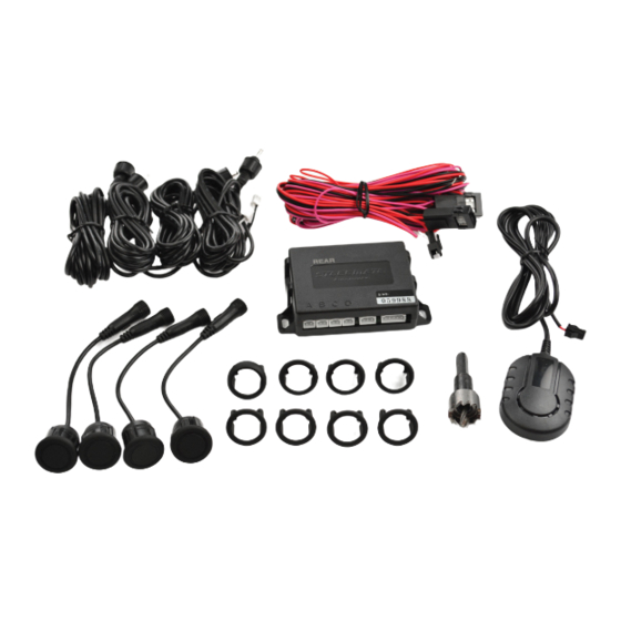
Packing list Sensor installation Installation tools Suggested sensor spacing is 45cm apart. On some vehicles this is unachievable due to the number plate location or bumper design. This will mean the distance between the centre two sensors will be greater (see illustration). - Page 12 Changing the sensor head angle. Take the silicone ring out. Insert the silicone ring into the sensor Make sure the degree marking is on top again. of the sensor.
- Page 13 Painting instructions Reassemble the sensor head. Disassemble the sensor. Key down the surface of the sensor with either a scotch pad or 1500 sandpaper. Mask off the area of the head you don't want to get paint on. Take the silicone ring out.
- Page 14 Make sure the head is free When the sensor is completely dry, put the from dust/dirt before silicone ring back in. painting. Clean the surface of the sensor thoroughly with a pre paint wipe, do not touch the surface again after cleaning.
- Page 15 If a gap is found between the bumper and the sensor head when using the 10 degree clip on head, adjust the angle of the hole as shown below. Make sure the size of the hole saw supplied in the kit matches the diameter of the sensors before drilling any holes.
-
Page 17: Buzzer Installation
Buzzer installation Wiring diagram (Front ECU) Front buzzer installation. ACC+ Reverse Light Brake Light Rear buzzer installation. The recommended buzzer installation locations are shown above. Note: connect A&D or B&C sensors if you want to achieve a 2-sensor system. -
Page 18: Wiring Diagram (Rear Ecu) 1
Wiring diagram (Rear ECU) 2 Wiring diagram (Rear ECU) 1 Note: the pink ACC+ wire is used to supply a clean live to the kit when the feed to the reverse light is under 9v or pulsed (not a clean live). ACC+ Reverse Light Reverse Light... -
Page 19: Function Test After Installation
Dear customer: After installation, the buzzer doesn’t work Complete the function test Thank you for choosing a Steelmate product. a) Are all the cables connected properly? by using a wooden board Please fill in the form below and retain it for b) Is the vehicles ignition on? (0.3x1.0m/1.0x3.3ft). - Page 20 Thank you for choosing a Steelmate product. This product comes with Steelmate UK’s standard 5 year warranty. Our standard 5 year warranty only covers parts. Steelmate are not liable and will not pay any labour costs incurred during the removal and/or re-installation of warranted equipment or parts.
Need help?
Do you have a question about the PTS400EX and is the answer not in the manual?
Questions and answers