Table of Contents
Advertisement
Quick Links
Instruction Manual
D103312X012
™
Fisher
GX 3-Way Control Valve and Actuator
System
Contents
. . . . . . . . . . . . . . . . . . . . . . . . . . . . . . . . .
. . . . . . . . . . . . . . . . . . . . . . . . . . . . .
. . . . . . . . . . . . . . . . . . . . . . . . . . . . . . . . .
. . . . . . . . . . . . . . . . . . . . . . . . . . . . . . .
. . . . . . . . . . . . . . . . . . . . . . . . . . . . .
. . . . . . . . . . . . . . . . . . . . . . . . . . . . . . . . .
. . . . . . . . . . . . . . . . . . . . . . . . . . . . . . . . . . .
. . . . . . . . . . . . . . . . . . . . . . . . . . . . . . . . . . .
Introduction
Scope of Manual
This instruction manual includes installation, maintenance, and parts information for the Fisher GX 3-Way control
Do not install, operate, or maintain a GX 3-Way valve without being fully trained and qualified in valve, actuator, and
accessory installation, operation, and maintenance. To avoid personal injury or property damage, it is important to
carefully read, understand, and follow all the contents of this manual, including all safety cautions and warnings. If you
have any questions about these instructions, contact your
proceeding.
Description
The GX 3-Way meets the requirements of both EN and ASME standards. It is available with a complete accessory
package, including the FIELDVUE
. . . . . . . . . . . . . . . . . . . . . . . . .
. . . . . . . . . . . . . . . . . . . . . . . .
. . . . . . . . . . . . . . . . . . . . . . . . .
. . . . . . . .
. . . . . . . . .
. . . . . . . . . . . . . . . . . . . . .
™
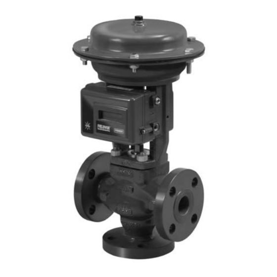
DVC2000 integrated digital valve controller.
Figure 1. Fisher GX 3-Way Control Valve, Actuator,
and FIELDVUE DVC2000 Digital Valve Controller
1
1
1
2
2
2
3
5
9
9
12
15
19
20
W9557
GX 3-WAY
Emerson sales office
GX 3-Way Valve and Actuator
X0218
GX 3-WAY
HIGH-TEMPERATURE
or Local Business Partner before
July 2017
Advertisement
Table of Contents

Related Manuals for Fisher GX 3-Way


Summary of Contents for Fisher GX 3-Way
-
Page 1: Table Of Contents
Do not install, operate, or maintain a GX 3-Way valve without being fully trained and qualified in valve, actuator, and accessory installation, operation, and maintenance. To avoid personal injury or property damage, it is important to carefully read, understand, and follow all the contents of this manual, including all safety cautions and warnings. -
Page 2: Specifications
1. Stainless steel valve body is recommended for steam service when the high temperature (HT) construction is selected. Educational Services For information on available courses for the Fisher GX 3-Way control valve and actuator system, as well as a variety of other products, contact:... -
Page 3: Maintenance
If hoisting the valve take care to prevent people from being injured in case the hoist or rigging slips. Be sure to use adequately sized hoists and chains or slings to handle the valve. Figure 2. Fisher GX 3‐Way Nameplate (Key 35) ELECTRIC ACTUATOR... - Page 4 Process fluids may spray out under pressure when removing the packing hardware or packing rings, or when loosening the packing box pipe plug. D Check with your process or safety engineer for any additional measures that must be taken to protect against process media. Figure 3. Fisher GX 3‐Way Valve Bottom‐Port Common Flow Direction GE37477_FLOWDIR...
-
Page 5: Actuator Maintenance
Instruction Manual GX 3-Way Valve and Actuator D103312X012 July 2017 Figure 4. Fisher GX 3‐Way Valve Side‐Port Common Flow Direction GE37477_FLOWDIR Table 2. Fisher GX 3‐Way Rated Travel VALVE SIZE TRAVEL STEM CONNECTOR GAP SETTINGS NUMBER OF CASING ACTUATOR SIZE BOLTS 1, 1‐1/2... - Page 6 Instruction Manual GX 3-Way Valve and Actuator July 2017 D103312X012 The following sections provide procedures for actuator maintenance. Refer to figures 8, 11, and 13. The actuator soft parts may require periodic replacement. This includes the diaphragm (key 10), diaphragm O-ring (key 109), actuator rod bushing (key 19), and the actuator rod seal (key 20).
- Page 7 Instruction Manual GX 3-Way Valve and Actuator D103312X012 July 2017 2. Remove the stem connector nut half (key 23), stem connector bolt half (key 24), and travel indicator (key 26). 3. Shut off the air pressure and disconnect the air supply to the upper casing.
- Page 8 Instruction Manual GX 3-Way Valve and Actuator July 2017 D103312X012 D For HT constructions, the valve body nuts (key 7) are tightened at the valve body (key 1) and at the top of the yoke extension (key 105), see figure 12.
-
Page 9: Packing Maintenance
Instruction Manual GX 3-Way Valve and Actuator D103312X012 July 2017 12. If you had previously removed the actuator assembly from the valve, place the actuator assembly back onto the valve body (key 1) or yoke extension (key 105, figure 12) for HT construction. Install the body nuts (key 7) and tighten evenly using a cross‐tightening procedure. - Page 10 Instruction Manual GX 3-Way Valve and Actuator July 2017 D103312X012 b. Remove the stem connector nut half (key 23), stem connector bolt half (key 24), and travel indicator (key 26). c. Push the valve plug stem (key 3) down until it contacts the lower seat.
- Page 11 Instruction Manual GX 3-Way Valve and Actuator D103312X012 July 2017 CAUTION To avoid property damage, place the actuator yoke on a protective surface, as described in the following procedure. 7. Carefully lift off the actuator and set it on a protective surface to prevent damage. If the bonnet (key 4) together with the valve stem plug assembly has a tendency to lift with the actuator, ensure it does not drop from the actuator.
-
Page 12: Replacing Packing (Electric Actuators)
Instruction Manual GX 3-Way Valve and Actuator July 2017 D103312X012 D For HT constructions, see figure 12. Install the locknut (key 108) and stem extension (key 106). Install the valve plug/bonnet sub assembly into the valve body (key 1). 19. Mount the actuator onto the valve and install the body nuts (figure 8 key 7), but tighten them only finger‐tight. - Page 13 Instruction Manual GX 3-Way Valve and Actuator D103312X012 July 2017 5. Push the valve plug stem (key 3) down until it contacts the lower seat. 6. Loosen the locknut (key 28) and thread the lower stem connector (key 27) down until it clears the top of the valve plug stem (key 3).
- Page 14 Instruction Manual GX 3-Way Valve and Actuator July 2017 D103312X012 13. Remove the bonnet and the valve plug/stem assembly and set on a protective surface. 14. Remove the valve/yoke gasket (key 5) and cover the opening of the valve to protect the gasket surface and prevent foreign matter from getting into the valve cavity.
-
Page 15: Valve Trim Maintenance
Loosen the packing follower 60_ of rotation. 30. Ensure that the electric actuator maximum thrust output does not exceed the values in table 5. Table 5. GX 3-Way Electric Actuator Maximum Allowable Thrust MAXIMUM THRUST STEM DIAMETER... - Page 16 Instruction Manual GX 3-Way Valve and Actuator July 2017 D103312X012 CAUTION Use care to avoid damaging the gasket sealing surfaces. The surface finish of the valve stem (key 3) is critical for making a good packing seal. The seating surfaces of the seat ring or cage (key 2) and the valve plug (key 3) are critical for tight shutoff and should therefore also be treated with care and properly protected.
- Page 17 Instruction Manual GX 3-Way Valve and Actuator D103312X012 July 2017 6. Install bonnet, and actuator yoke onto the valve body by completing the assembly according to steps 14 to 27 of the section Replacing Packing, omitting step 17 if new packing is not being installed.
- Page 18 Instruction Manual GX 3-Way Valve and Actuator July 2017 D103312X012 Table 7. Seat Ring and Cage Torque Requirements VALVE SIZE TORQUE lbfSft 1‐1/2 1020 80 and 100 3 and 4 1520 1113 5. Clean the body/yoke gasket surfaces and install a new body/yoke gasket (key 5).
-
Page 19: Parts Kits
Use only genuine Fisher replacement parts. Components that are not supplied by Emerson Automation Solutions should not, under any circumstances, be used in any Fisher valve, because they may void your warranty, might adversely affect the performance of the valve, and could cause personal injury and property damage. -
Page 20: Parts List
Instruction Manual GX 3-Way Valve and Actuator D103312X012 July 2017 Parts List Description Seal Ring see bottom-port common seal kits table Note Backup Ring see bottom-port common seal kits table Contact your Emerson sales office or Local Business Partner for part... - Page 21 Instruction Manual GX 3-Way Valve and Actuator D103312X012 July 2017 Figure 7. Fisher GX 3‐Way Packing GE37477_ULF GE37477_PACK ENVIRO-SEAL PTFE PACKING ENVIRO-SEAL GRAPHITE ULF PACKING...
-
Page 22: Valve And Actuator System
Instruction Manual GX 3-Way Valve and Actuator July 2017 D103312X012 Figure 8. Fisher GX 3‐Way Control Valve and Actuator System Assembly, Fail‐Up, Side‐Port Common SIDE‐PORT COMMON AIR SUPPLY CONNECTION BACK SIDE APPLY LUBRICANT GE35775‐D... - Page 23 Instruction Manual GX 3-Way Valve and Actuator D103312X012 July 2017 Figure 9. Fisher GX 3‐Way Side Port Common Trim Construction SIDE‐PORT COMMON GE37477_SP_TRIM Figure 10. Fisher GX 3‐Way Bottom‐Port Common Trim Construction BOTTOM‐PORT COMMON GE37477_BP_TRIM...
-
Page 24: Valve And Actuator System
Instruction Manual GX 3-Way Valve and Actuator July 2017 D103312X012 Figure 11. Fisher GX 3‐Way Control Valve and Actuator System Assembly, Fail‐Down, Bottom‐Port Common BOTTOM‐PORT COMMON AIR SUPPLY CONNECTION GE35776‐d APPLY LUBRICANT BACK SIDE... -
Page 25: Valve And Actuator System
Instruction Manual GX 3-Way Valve and Actuator D103312X012 July 2017 Figure 12. Fisher GX 3‐Way High-Temperature Control Valve and Actuator System Assembly, Fail‐Up, Side‐Port Common SIDE‐PORT COMMON AIR SUPPLY CONNECTION BACK SIDE GE49204‐C APPLY LUBRICANT... - Page 26 Instruction Manual GX 3-Way Valve and Actuator July 2017 D103312X012 Figure 13. Fisher GX 3‐Way Electric Actuator Mounting GG12175-A...
- Page 27 Instruction Manual GX 3-Way Valve and Actuator D103312X012 July 2017...
-
Page 28: Www.fisher.com
Responsibility for proper selection, use, and maintenance of any product remains solely with the purchaser and end user. Fisher, FIELDVUE, and ENVIRO-SEAL are marks owned by one of the companies in the Emerson Automation Solutions business unit of Emerson Electric Co.
Need help?
Do you have a question about the GX 3-Way and is the answer not in the manual?
Questions and answers