
Related Manuals for Emerson Unidrive SPM


Summary of Contents for Emerson Unidrive SPM
- Page 1 User Guide Unidrive SPM Universal Variable Speed AC Drive Modular Solutions for induction and servo motor applications Part Number: 0471-0053-03 Issue: 3 www.controltechniques.com...
- Page 2 General Information The manufacturer accepts no liability for any consequences resulting from inappropriate, negligent or incorrect installation or adjustment of the optional operating parameters of the equipment or from mismatching the variable speed drive with the motor. The contents of this guide are believed to be correct at the time of printing. In the interests of a commitment to a policy of continuous development and improvement, the manufacturer reserves the right to change the specification of the product or its performance, or the contents of the guide, without notice.
- Page 3 How to use this guide This guide provides complete information for installing and operating a Unidrive SPMA and SPMD, with a SPMC or SPMU rectifier, from start to finish. The information is in logical order, taking the reader from receiving the drive through to fine tuning the performance. NOTE There are specific safety warnings throughout this guide, located in the relevant sections.
-
Page 4: Table Of Contents
Changing the operating mode ......124 5.14 Routine maintenance ..........63 Changing keypad mode ........124 Quick Start commissioning/start-up ....128 Quick start commissioning/start-up (CTSoft) ... 132 Setting up a feedback device ......132 Unidrive SPM User Guide www.controltechniques.com Issue Number: 3... - Page 5 13.18 Menu 20: Application menu 3 ......251 13.19 Menu 21: Second motor parameters ....252 13.20 Menu 22: Additional Menu 0 set-up ....253 13.21 Advanced features ..........254 Technical Data ........263 14.1 Drive ..............263 14.2 Optional external EMC filters ......273 Unidrive SPM User Guide Issue Number: 3 www.controltechniques.com...
-
Page 6: Declaration Of Conformity
Refer to the User Guide. An EMC Electromagnetic compatibility (EMC). Generic Data Sheet is also available giving detailed EMC information. EN 61000-6-2 standards. Immunity standard for industrial environments Unidrive SPM User Guide www.controltechniques.com Issue Number: 3... -
Page 7: Safety Information
It may be used in a safety-related application. The system designer is responsible for ensuring that the complete system is safe and designed correctly according to the relevant safety standards. Independent approval by BGIA has been given. Unidrive SPM User Guide Issue Number: 3 www.controltechniques.com... -
Page 8: Introduction
The status relay contacts are rated for switching non-inductive loads at 250Vac 6A non-inductive, up to 4Adc if the voltage is limited to 40V or up to 400mA dc if the voltage is limited to 250Vdc. Protection from overcurrent must be provided. Unidrive SPM User Guide www.controltechniques.com Issue Number: 3... -
Page 9: Spma Inverter
236A (400V drive). DC connections are available for use in regen and bus-parallel applications. The SPMA is available with or without a braking IGBT fitted. Figure 2-5 SPMA inverter schematic Optional Unidrive SPM User Guide Issue Number: 3 www.controltechniques.com... -
Page 10: Spmd Inverter
Supply Drive 2 U V W For a physical representation of the input line reactors and output NOTE sharing chokes, see Figure 3-4 on page 21. This is not an interbridge reactor. Unidrive SPM User Guide www.controltechniques.com Issue Number: 3... -
Page 11: Model Number
Data Information Model number Figure 2-13 Input line reactor / output sharing choke The way in which the model numbers for the Unidrive SPM range are formed is illustrated below. Figure 2-11 Rectifier (SPMC and SPMU) SPMC 1 Input line reactor... -
Page 12: Product Information
Data Information Product Information Ratings The Unidrive SPM is dual rated. Available output Overload limit - The setting of the motor rated current determines which rating applies - current Heavy Duty Heavy Duty or Normal Duty. -
Page 13: Table 3-1 Spma 400V Drive Ratings (380V To 480V ±10%)
Model consumption output current power power output peak peak power power current at 690V at 575V current current current at 690V at 575V SPMA16X1 SPMA16X2 Unidrive SPM User Guide Issue Number: 3 www.controltechniques.com... -
Page 14: Table 3-4 Paralleled Spma 690V Motor Drive Ratings (500V To 690V ±10%)
(undocked). Changes in the flow of air mean that the ratings are different for the two mounting methods for SPMD14x4. For details on docking, refer to section 5.6 Docking a Unidrive SPMC/U to an SPMD on page 39. Unidrive SPM User Guide www.controltechniques.com... -
Page 15: Table 3-7 Spmd 400V Motor Drive Ratings (380V To 480V ±10%) Based On Ac Supply Voltage
690V at 575V current current current at 690V at 575V SPMD16X1 1 x INL601 SPMD16X2 SPMC/U1601 SPMD16X3 1 x INL602 SPMD16X4 Unidrive SPM User Guide Issue Number: 3 www.controltechniques.com... -
Page 16: Table 3-10 Paralleled Spmd 690V Motor Drive Ratings (500V To 690V ±10%) Based On Ac Supply Voltage
Menu 4 in the Unidrive SP Advanced User Guide. Typical values are shown in the tables below for closed loop vector (VT) and open loop (OL) modes. Table 3-13 Typical overload limits for all Unidrive SPM modules Closed loop/RFC/... -
Page 17: Operating Modes
Information Operating modes For further details refer to section 10.1.4 Servo motor control on page 144. The Unidrive SPM is designed to operate in any of the following modes: 3.2.5 Regen 1. Open loop mode For use as a regenerative front end for four quadrant operation. -
Page 18: Features
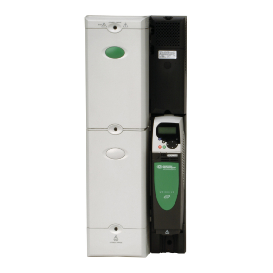
Information configuration Installation Installation Started parameters the motor operation parameters Data Information Features Figure 3-1 Features of the Unidrive SPM Modules Control master pod Control slave pod Cover Base SMARTCARD slot Approvals label B Keypad connection Status LED Status Serial port... -
Page 19: Nameplate Description
Data Information Nameplate description See Figure 3-1 Features of the Unidrive SPM Modules for location of rating labels. Figure 3-2 Typical drive rating labels Approvals label A (SPMA / SPMD - Master and Slave) Heavy Duty / Model... -
Page 20: Options
Started parameters the motor operation parameters Data Information Options Power down the drive before installing / removing the Solutions Module. WARNING Figure 3-3 Control options available with Unidrive SPM SMARTCARD* Keypad Master interface Feedback Automation Fieldbus CT Comms cable Slave... -
Page 21: Figure 3-4 Power Options Available For Unidrive Spm
CAUTION All Unidrive SPM Solutions Modules are color-coded in order to make identification easy. The following table shows the color-code key and gives further details on their function. Power down the drive before installing / removing the Solutions Module. - Page 22 Applications Processor (with CTNet) SM-Applications processor for running pre-defined and /or customer created Moss Green Plus application software with CTNet support. Enhanced performance over SM-Applications. Unidrive SPM User Guide www.controltechniques.com Issue Number: 3...
-
Page 23: Table 3-16 Keypad Identification
SM-Keypad Plus Keypad with an alpha-numeric LCD display with Help function Table 3-17 Other options Type Option Name Further Details Power 24V power supply 24V, 10A power supply (Part No: 8510-0000) supply Unidrive SPM User Guide Issue Number: 3 www.controltechniques.com... -
Page 24: Items Supplied With The Drive
Information Items supplied with the drive The drive is supplied with a copy of the Unidrive SPM User Guide, a SMARTCARD (control master pod only), the safety booklet, the certificate of quality, an accessory kit box including the items shown in Table 3-18, and two CD ROMs. -
Page 25: System Configuration
Information System configuration This chapter demonstrates various Unidrive SPM system configurations. A suitable external 24Vdc power supply is available from the supplier of the drive. See section 14.1.4 Unidrive SPM 24V power supply on page 267 for further details. Figure 4-1 Layout for a Unidrive SPMA module operating on a 3-phase AC supply... -
Page 26: Figure 4-2 Layout For Two Or More Unidrive Spma Modules Operating On A 3-Phase Ac Supply
***Refer to section 14.1.3 Supply requirements on page 267 for supply requirements. Refer to the external 24V power supply current consumption column in the ratings tables in section 3.1 Ratings on page 12. Unidrive SPM User Guide www.controltechniques.com Issue Number: 3... -
Page 27: Figure 4-3 Layout For An Unidrive Spmd Module Operating On A 3-Phase Supply
***Refer to Table 6-2, Table 6-3, Table 6-4 and Table 6-5 on page 68 for technical data and part numbers. ****Refer to section 14.1.3 Supply requirements on page 267 for supply requirements. Unidrive SPM User Guide Issue Number: 3 www.controltechniques.com... -
Page 28: Figure 4-4 Layout For An Unidrive Spmd Module Operating On A 3 Phase Supply With Spmu (Uncontrolled) Rectifier And Softstart Circuit
14.1.3 Supply requirements on U V W page 267 for supply requirements. 24Vdc**** For softstart circuit component sizing, refer Fuses** to section 6.5 Resistor sizing for Unidrive SPMU softstart on page 70. Unidrive SPM User Guide www.controltechniques.com Issue Number: 3... -
Page 29: Figure 4-5 Layout For Two Or More Unidrive Spmd Modules Operating On A 3-Phase Ac Supply
Unidrive SPM User Guide Issue Number: 3 www.controltechniques.com... -
Page 30: Figure 4-6 Layout For Two Unidrive Spmd Modules With A Dual Spmc Rectifier Operating On A 3-Phase Ac Supply
Also, on the input side, input current sharing is determined only by making the temperature of the two rectifiers similar and by ensuring that both rectifiers see the same impedance to the line power supply. Unidrive SPM User Guide www.controltechniques.com Issue Number: 3... -
Page 31: Figure 4-7 Layout For Two Unidrive Spmd Slave Modules With A Dual Spmc Rectifier Operating On A 3-Phase Ac Supply With A Remote Mounted Control Master Pod
The remote mounted control master pod allows the user to place all control circuitry in one low voltage cabinet and permits up to a maximum of 10 Unidrive SPMD modules to be connected in parallel. Unidrive SPM User Guide Issue Number: 3 www.controltechniques.com... -
Page 32: Figure 4-8 Parallel Control Connections
The parallel cable should be routed according to the rules shown in Figure 6-25 Sensitive signal circuit clearance on page 84 for the control cable. NOTE The screw locks on the parallel cable must be fully tightened. Unidrive SPM User Guide www.controltechniques.com Issue Number: 3... -
Page 33: Mechanical Installation
An anti-condensation heater may be required, which input and output terminal covers. must be switched off when the drive is running. Unidrive SPM/C are fitted with two terminal covers: Input and output • contamination with electrically conductive material terminal covers. For the dual SPMC/U rectifier, the terminal covers and •... -
Page 34: Figure 5-1 Location And Identification Of Terminal Covers
Information Information configuration Installation Installation Started parameters the motor operation parameters Data Information Figure 5-1 Location and identification of terminal covers Input Input Input SPMA SPMD SPMC/U Output Control Output Control Output Unidrive SPM User Guide www.controltechniques.com Issue Number: 3... -
Page 35: Figure 5-2 Removing The Terminal Covers
When removing the Unidrive SPMC/U dual rectifier centre housing, undo the 3 x T25 torx head screws as shown in Figure 5-3. When the housing is replaced, the screws should be tightened with a maximum torque of 2.5 N m (1.8 lb ft). Unidrive SPM User Guide Issue Number: 3... -
Page 36: Figure 5-4 Removing The Finger-Guard Break-Outs
(1). Continue until all required break-outs are removed (2). Remove any flash / sharp edges once the break-outs are removed. Grommets are available for the Unidrive SPM finger-guards. Two versions are available allowing for either single or double cable entries. NOTE These grommets are required to meet IP20 when installed in an open environment. -
Page 37: Solutions Module Installation/Removal
(B). NOTE The keypad can be installed / removed while the drive is powered up and running a motor, providing that the drive is not operating in keypad mode. Unidrive SPM User Guide Issue Number: 3 www.controltechniques.com... -
Page 38: Mounting Of Control Master/Slave Pod
3. The terminal covers can then be re-installed. Ensure that the connector on the back of the control master/slave pod (1) is securely fitted to the power module metal base plate connector (2). Unidrive SPM User Guide www.controltechniques.com Issue Number: 3... -
Page 39: Docking A Unidrive Spmc/U To An Spmd
(Derating for switching frequency and temperature) on page 263. 5.6.1 Installing the docking kit When mounting an SPMD and SPMC/U in a vertical plane, as shown in Figure 5-17 on page 43 and Figure 5-21 on page 46, the following Unidrive SPM User Guide Issue Number: 3 www.controltechniques.com... -
Page 40: Figure 5-13 Location Of The Docking Kit When Installed
A current derating must be applied to the Unidrive SPMD1404 when docked with the Unidrive SPMC/U. Details can be found insection 14.1.1 Power and current ratings (Derating for switching frequency and temperature) on page 263. Unidrive SPM User Guide www.controltechniques.com Issue Number: 3... -
Page 41: Mounting Methods
258.6 0.5mm ± ∅8.5mm (10.181 0.020in) ± 310mm (12.205in) 298mm (11.732in) (0.335in) 18.9mm (0.744in) 25.7 0.5mm ± (1.012 0.020in) ± 1131mm 1168.8mm 1150.8 ±0.5mm (44.528in) (45.307 0.020in) ± (46.016in) 18.9mm (0.744in) ∅8.5mm (0.335in) Unidrive SPM User Guide Issue Number: 3 www.controltechniques.com... -
Page 42: Figure 5-15 Surface Mounting The Unidrive Spmd
310.1mm (12.209in) 297.4mm (11.709in) (0.335in) 18.3mm (0.720in) 25.7 0.5mm ± (1.012 0.020in) ± 380.5 ±0.5mm 399.1mm 386.4mm (15.713in) (14.980 ±0.020in) (15.213in) 145.3 0.25mm ± 90.3 0.25mm ± (5.720 0.010in) ± (3.555 0.010in) ± Unidrive SPM User Guide www.controltechniques.com Issue Number: 3... -
Page 43: Figure 5-17 Surface Mounting The Unidrive Spmd With Spmc/U (Rectifier) And Docking Kit
A current derating must be applied to the Unidrive SPMD1404 when docked with the Unidrive SPMC/U. Details can be found in section 14.1.1 Power and current ratings (Derating for switching frequency and temperature) on page 263. Unidrive SPM User Guide Issue Number: 3 www.controltechniques.com... -
Page 44: Figure 5-18 Through-Panel Mounting The Unidrive Spma
1131mm 1179.3mm ± 0.5mm 1105.6mm 1107.8 0.5mm ± (44.528in) (46.429in) (45.717 (43.528in) (43.614 0.020in) ± ± 0.020in) R6.5mm (0.256in) 13.7± 0.5mm (0.539 0.020in) ± ∅8.5mm 258.6 0.5mm ± (0.335in) (10.181 0.020in) ± Unidrive SPM User Guide www.controltechniques.com Issue Number: 3... -
Page 45: Figure 5-19 Through-Panel Mounting The Unidrive Spmd
345.9 0.5mm ± 386.4mm (15.244 (13.461in) (13.618 0.020in) ± (15.213in) ±0.020in) R6.5mm (0.256in) ∅8.5mm (0.335in) 13.7± 0.5mm (0.539 0.020in) ± 145.3 0.25mm ± 113.3 0.25mm ± (5.720 0.010in) ± (4.461 0.010in) ± Unidrive SPM User Guide Issue Number: 3 www.controltechniques.com... -
Page 46: Figure 5-21 Through-Panel Mounting The Unidrive Spmd With Spmc/U (Rectifier) And Docking Kit
A current derating must be applied to the Unidrive SPMD when docked with the Unidrive SPMC/U. Details can be found insection 14.1.1 Power and current ratings (Derating for switching frequency and temperature) on page 263. Unidrive SPM User Guide www.controltechniques.com Issue Number: 3... -
Page 47: Figure 5-22 Unidrive Spm Mounting Bracket
5.7.4 Installation of the Unidrive SPM mounting brackets Common The Unidrive SPM range use the same mounting brackets for surface and through-panel mounting. The mounting bracket has a long section and a short section. Figure 5-22 Unidrive SPM mounting bracket... -
Page 48: Figure 5-26 Installation Of The Unidrive Spmc/U Through Panel Mounting Brackets
Information Figure 5-26 Installation of the Unidrive SPMC/U through panel mounting brackets 1. Common Unidrive SPM mounting bracket. Ensure short section attached to backplate 2. Unidrive SPMC/U supply ground bracket. M10x20 screw required to mount bracket, maximum length 40mm (1.575in) used with vibration resistant washer. -
Page 49: Enclosure
≥100mm Locate the overload (4in) Fan supply: 24Vdc protection device as required SPMA: 3.3A SPMD1401 & 1402: 6.3A SPMD1403 & 1404: 7.6A Optional braking resistor and overload Unidrive SPM User Guide Issue Number: 3 www.controltechniques.com... -
Page 50: Figure 5-28 Alternative Enclosure Layout: Undocked Unidrive Spmd And Spmc
NOTE The Unidrive SPMC must not be mounted any higher than the SPMD. This is to prevent the heated air expelled from the Unidrive SPMD being recirculated through the SPMC. Unidrive SPM User Guide www.controltechniques.com Issue Number: 3... -
Page 51: Figure 5-29 Altitude Derate Factor
1.015 1.01 1.005 0.995 ° Temperature ( C) Note: • The ambient temperature correction factor used is for altitude calculation only. If the ambient is less than 40°C the drive cannot be Unidrive SPM User Guide Issue Number: 3 www.controltechniques.com... -
Page 52: Figure 5-31 Enclosure Design Example
(e.g. paralleling derates, switching frequency derates, ambient derate etc). For front view of enclosure, refer to Figure 5-31. Spacing between units and sides of enclosure: >60mm Unidrive SPM User Guide www.controltechniques.com Issue Number: 3... -
Page 53: Figure 5-33 Recirculation Factor
Data Information Calculation of temperature rise in enclosure Calculate temperature rise Table 5-3 Unidrive SPM air flow rates Inputs Table 5-2 Example data Modules Flow rate (m3/hr) Output sharing choke loss under single unit (L2) 250W... -
Page 54: Heatsink Fan Operation
System operating point is: ventilate the capacitor bank. Static pressure = 34 Pa All Unidrive SPM models require an external 24Vdc supply to drive the Flow rate= 4212.5 m fans. See section 6-12 Location of the heatsink fan supply connections (SPMA &... -
Page 55: Figure 5-36 Removal Of Unidrive Spma/D Fan (Part 1)
3. Slide fan cassette out of heatsink chamber 4. Remove fan screws in order to remove fan from cassette Figure 5-38 Removal of Unidrive SPMC/U fan Table 5-5 Unidrive SPM fan assembly part numbers NOTE The following rectifiers only have one fan included in their assembly:... -
Page 56: Enclosing Drive For High Environmental Protection
The main gasket should be installed as shown in Figure 5-39. Any screws / bolts that are used for mounting should be installed with the nylon washers provided in the kit box to maintain a seal around the screw hole. See Figure 5-40. Unidrive SPM User Guide www.controltechniques.com Issue Number: 3... -
Page 57: Figure 5-40 Option 2 For Achieving Ip54 (Nema 12) Through-Panel Mounting
Table 5-7 Quantity of nylon washers included in the kit boxes Item Description Size Quantity of M8 (A) Quantity of M6 (B) Bolt Flat washer Nylon washer (from kitbox) Flat washer Spring washer Unidrive SPM User Guide Issue Number: 3 www.controltechniques.com... -
Page 58: External Emc Filter
Figure 5-42 Mounting the external EMC filter drive. Table 5-9 Power losses from the front of the drive when through- panel mounted Model Power loss ≤480W SPMA ≤300W SPMD ≤50W SPMC ≤50W SPMU Unidrive SPM User Guide www.controltechniques.com Issue Number: 3... -
Page 59: Figure 5-43 External Emc Filter
4200-6313 220 mm 170 mm 43 mm 149 mm 76 mm 60 mm 339 mm Ib ft) (8.661 in) (6.700 in) (1.700 in) (5.866 in) (3.000 in) (2.362 in) (13.346 in) 4200-6314 Unidrive SPM User Guide Issue Number: 3 www.controltechniques.com... -
Page 60: Figure 5-44 Multiple Drive Emc Filters
(5.71±0.02in) 52±3mm 460±2.5mm 4200-6802 Epcos (2.05±0.12in) (18.11±0.1in) 80mm 300mm 275±1mm 2.5mm 166mm 15.5 N m (3.15in) (11.81in) (10.83±0.04in) (0.1in) (6.54in) (11.4 lb ft) 400mm 170±0.5mm 92±3mm 590±3mm 4200-6803 (15.75in) (6.71±0.02in) (3.62±0.12in) (23.23±0.12in) Unidrive SPM User Guide www.controltechniques.com Issue Number: 3... -
Page 61: Line Reactor Mounting Dimensions
± sharing choke specification on page 69. 7.5mm (0.3in) 8.5 0.5mm ± (0.17 0.02in) ± For overall dimensions and other details, refer to section 6.2.2 Input line reactor specifications on page 67. Unidrive SPM User Guide Issue Number: 3 www.controltechniques.com... -
Page 62: Electrical Terminals
Data Information 5.13 Electrical terminals 5.13.1 Location of the power and ground terminals Figure 5-50 Locations of the power and ground terminals on Unidrive SPM Master interface Control terminals Relay terminals 2.5mm 8mm AF 8mm AF AC IN... -
Page 63: Routine Maintenance
Screw connections Ensure all screw terminals remain tight Ensure all crimp terminals remains tight – Crimp terminals check for any discoloration which could indicate overheating Cables Check all cables for signs of damage Unidrive SPM User Guide Issue Number: 3 www.controltechniques.com... -
Page 64: Electrical Installation
WARNING If the motor load is capable of rotating the motor when the supply is disconnected, then the motor must be isolated from the drive before gaining access to any live parts. Unidrive SPM User Guide www.controltechniques.com Issue Number: 3... -
Page 65: Power Connections
** See section 6-12 Location of the heatsink fan supply connections ** See section 6-12 Location of the heatsink fan supply connections (SPMA & SPMD) on page 73 for more information. (SPMA & SPMD) on page 73 for more information. Unidrive SPM User Guide Issue Number: 3 www.controltechniques.com... -
Page 66: Figure 6-3 Unidrive Spma Ground Connections
SPMA: 75mm SPMD: 120mm SPMC/U: 128mm Figure 6-3 Unidrive SPMA ground connections Supply ground Motor ground Figure 6-5 Unidrive SPMC/U ground connections Supply ground Motor ground Motor ground Unidrive SPM User Guide www.controltechniques.com Issue Number: 3... -
Page 67: Ac Supply Requirements
Drives rated for supply voltage up to 575V are suitable for use with any supply type, i.e. TN-S, TN-C-S, TT, IT, with grounding at any potential, i.e. neutral, centre or corner ("grounded-delta"). Grounded delta supplies >575V are not permitted. Unidrive SPM User Guide Issue Number: 3 www.controltechniques.com... -
Page 68: Table 6-2 400V Input Line Reactor Ratings
Drives of low power rating may also be susceptible to disturbance when connected to supplies with a high rated capacity. When required, each drive must have its own reactor(s). Three individual reactors or a single three-phase reactor should be used. Unidrive SPM User Guide www.controltechniques.com Issue Number: 3... -
Page 69: Output Sharing Choke Specification
Output sharing choke specification In order to achieve the best possible current sharing between paralleled Unidrive SPM modules, sharing chokes must be installed between the motor output connections and the drive’s motor connections. Table 6-6 400V output sharing choke ratings... -
Page 70: Supplying The Drive With Dc / Dc Bus Paralleling
See Figure 6-15. MCBs available adding the DC bus capacitances of each drive that is to be started by from Control Techniques can be found in Table 6-13. the soft-start circuit. Unidrive SPM User Guide www.controltechniques.com Issue Number: 3... -
Page 71: Table 6-10 Dc Bus Capacitance And Peak Supply Current Values
W = 1.45 x 13200 x 10 x 230 DC bus capacitance values and peak allowable supply current for Unidrive SPM drives are as follows. W = 1013J Step 3 Table 6-10 DC bus capacitance and peak supply current values... -
Page 72: Figure 6-10 Example Of Resistor Overload Characteristic
Many different MCBs are possible, e.g.: • GB2CB range from Telemecanique • S 281-K range from ABB Unidrive SPM User Guide www.controltechniques.com Issue Number: 3... -
Page 73: Heatsink Fan Supply
<20A For application data, refer to the Unidrive SP Low Voltage DC Installation Guide. SPMD14X1 and 14X2 4A fast blow (I t <20A SPMD14X3 and 14X4 6.3A fast blow (I t <100A Unidrive SPM User Guide Issue Number: 3 www.controltechniques.com... -
Page 74: Ratings
2 x 4/0 2 x 120 2 x 4/0 B1 or C SPMC/U2402 2 x 312 2 x 345 2 x 120 2 x 4/0 2 x 120 2 x 4/0 B1 or C Unidrive SPM User Guide www.controltechniques.com Issue Number: 3... -
Page 75: Output Circuit And Motor Protection
AC supply. power connections: • AC supply to external EMC filter (when used) • AC supply (or external EMC filter) to drive • Drive to motor • Drive to braking resistor Unidrive SPM User Guide Issue Number: 3 www.controltechniques.com... -
Page 76: Figure 6-14 Cable Construction Influencing The Capacitance
For normal operation with AC supplies up to 500Vac and a standard motor with a good quality insulation system, there is no need for any special precautions. In case of doubt the motor supplier should be consulted. Unidrive SPM User Guide www.controltechniques.com Issue Number: 3... -
Page 77: Braking
Opening or closing of the contactor with the drive enabled will lead to: 1. OI.AC trips (which cannot be reset for 10 seconds) 2. High levels of radio frequency noise emission 3. Increased contactor wear and tear Unidrive SPM User Guide Issue Number: 3 www.controltechniques.com... -
Page 78: Figure 6-17 Typical Protection Circuit For A Braking Resistor
** Continuous rating if drive is part of a common DC bus system. In parallel systems without the DC bus connected, the resistors must be The Unidrive SPM software contains an overload protection function for matched to within ±5%. a braking resistor. In order to enable and set-up this function, it is... -
Page 79: Ground Leakage
Section 6.13.4, Requirements for meeting the EMC standard for power drive systems, IEC61800-3 (EN61800-3). Section 6.13.5, Requirements for meeting the generic emission standards for the industrial environment, IEC61000-6-4, EN61000-6-4, EN50081-2. Unidrive SPM User Guide Issue Number: 3 www.controltechniques.com... -
Page 80: Figure 6-19 Removal Of Internal Emc Filter
56mA is unacceptable or the above conditions are true. See Figure 6-19 for details of removing and installing the internal EMC filter. Figure 6-19 Removal of internal EMC filter Loosen screws (1). Remove EMC filter in the direction shown (2). Unidrive SPM User Guide www.controltechniques.com Issue Number: 3... -
Page 81: Figure 6-20 General Emc Enclosure Layout Showing Ground Connections
The ground conductor in the motor cable must be connected directly to the earth terminal of the drive and motor. It must not be connected directly to the power earth busbar. Optional ground connection Unidrive SPM User Guide Issue Number: 3 www.controltechniques.com... -
Page 82: Figure 6-21 Drive Cable Clearances
Shielding considerations are important for PWM drive installations due to the high voltages and currents present in the output (motor) circuit with a very wide frequency spectrum, typically from 0 to 20 MHz. The following guidance is divided into two parts: Unidrive SPM User Guide www.controltechniques.com Issue Number: 3... -
Page 83: Figure 6-22 Feedback Cable, Twisted Pair
This is a product of the restricted distribution class according to IEC 61800-3 In a residential environment this product may cause radio interference in which case the user may be required to take CAUTION adequate measures. Unidrive SPM User Guide Issue Number: 3 www.controltechniques.com... -
Page 84: Figure 6-24 Supply And Ground Cable Clearance
Figure 6-25 Sensitive signal circuit clearance cables are at least 100mm from the power module and motor cable. Figure 6-24 Supply and ground cable clearance ≥100mm (4in) ≥100mm (4in) ≥300mm (12in) Sensitive signal cable ≥100mm (4in) Unidrive SPM User Guide www.controltechniques.com Issue Number: 3... -
Page 85: Figure 6-26 Grounding The Drive, Motor Cable Shield And
An internal ground core will carry a high noise current and therefore it must be terminated as close as possible to the shield termination. Figure 6-27 Grounding the motor cable shield Unidrive SPM User Guide Issue Number: 3 www.controltechniques.com... -
Page 86: Figure 6-29 Grounding Of Signal Cable Shields Using The Grounding Bracket
Installing a motor isolator/disconnect switch for safety when work is additional precautions are advisable. One of the following techniques done on the motor should be used: In these cases the following guidelines should be followed. Unidrive SPM User Guide www.controltechniques.com Issue Number: 3... -
Page 87: Spmc/U Control Connections
4A fast blow (I t <20A NOTE If the Unidrive SPM power supply (CT part number 8510-0000) is used to supply the Unidrive SPMA/D or SPMC/U, a fuse on the 24V supply to the SPMC/U is not required. Unidrive SPM power supply... -
Page 88: Figure 6-36 Single Module Control Terminals And
External 24V supply 0V common Status output 0 0V common Status output 1 0V common Rectifier OK Relay contacts Inverter (master) SPMD 0V common Status 1 input 0V common Status 0 input Unidrive SPM User Guide www.controltechniques.com Issue Number: 3... -
Page 89: Figure 6-37 Parallel Rectifier Control Terminals And
0V common terminal to +24V Common connection for all external Voltage range 0V to 24V supply voltage +2V Function devices Input threshold Ω Input resistance 6.8k Unidrive SPM User Guide Issue Number: 3 www.controltechniques.com... -
Page 90: Low Voltage Dc Mode Enable, Heatsink Fan Supply Connections (Spma/D) And Status Input Connections (Spmd)
The SPMD drive will monitor the status lines and on detection of a fault To the heatsink fan disables the system via a PhP or (when used in conjunction with a Pre-wired internally SPMC) OHT4.P trip. Unidrive SPM User Guide www.controltechniques.com Issue Number: 3... -
Page 91: Figure 6-41 Spmd Low Voltage Dc Mode Enable
Recommended fuse SPMD14X3/14X4: 6.15.3 SPMA status input connections 6.3A fast blow (I t >100A SPMD16X1/16X2: 4A fast blow (I t >20A No connection SPMD16X3/16X4: 6.3A fast blow (I t >100A No user connections Unidrive SPM User Guide Issue Number: 3 www.controltechniques.com... -
Page 92: Serial Communications Connections
Control connections - master interface Isolated 0V 6.17.1 General TX enable RX\ TX\ Table 6-28 The Unidrive SPM control connections consist of: RX\ TX\ (if termination resistors are required, link to pin 1) Terminal Function Control parameters available number Shell... -
Page 93: Figure 6-43 Default Terminal Functions
With software V01.06.02 and earlier, Analog input 3 has no default function. Refer to Analog input 3 on page 94. **The SAFE TORQUE OFF (SECURE DISABLE) / Drive enable terminal is a positive logic input only. Unidrive SPM User Guide Issue Number: 3 www.controltechniques.com... - Page 94 T8 analog input 3 has a parallel connection to terminal 15 of the drive encoder connector. Unidrive SPM User Guide www.controltechniques.com Issue Number: 3...
- Page 95 4ms in all other cases. Maximum output current 240mA (including all digital I/O) Protection Current limit and trip 0V common Common connection for all external Function 0V common devices Common connection for all external Function devices Unidrive SPM User Guide Issue Number: 3 www.controltechniques.com...
-
Page 96: Encoder Connections
The UVW commutation signals are used to define the motor position during the first 120° electrical rotation after the drive is powered-up or the encoder is initialized. Unidrive SPM User Guide www.controltechniques.com Issue Number: 3... -
Page 97: Table 6-30 Drive Encoder Connector Details
The addition of this filter means that SSI only encoders are not suitable for speed feedback in dynamic or high-speed applications. Unidrive SPM User Guide Issue Number: 3 www.controltechniques.com... -
Page 98: Table 6-31 Feedback Resolution Based On Frequency And Voltage Level
±4V and common mode voltage range Line loading <2 unit loads For the SinCos encoder to be compatible with Unidrive SPM, the output Ω Line termination components (switchable) signals from the encoder must be a 1V peak to peak differential voltage Working common mode range +12V to –7V... -
Page 99: Safe Torque Off (Secure Disable)
(elevator). function within the drive. Independent approval has been given by BGIA. Independent approval of concept has been given by TÜV. Please consult the separate guide for lift applications for further information. Unidrive SPM User Guide Issue Number: 3 www.controltechniques.com... -
Page 100: Figure 6-45 Start / Stop Control En954-1 Category B - Replacement Of Contactor
For further applications guidance, refer to the Unidrive SP Advanced User Guide. Unidrive SPM User Guide www.controltechniques.com Issue Number: 3... -
Page 101: Getting Started
The display examples in this section show the SM-Keypad 7 segment LED display. The examples are the same for the SM-Keypad Plus except that the information displayed on the lower row on the SM-Keypad is displayed on the right hand side of the top row on the SM-Keypad Plus. Unidrive SPM User Guide Issue Number: 3... -
Page 102: Menu Structure
NOTE For new parameter-values to apply after the AC supply to the drive is interrupted, new values must be saved. Refer to section 7.7 Saving parameters on page 105. Unidrive SPM User Guide www.controltechniques.com Issue Number: 3... -
Page 103: Menu 0
Appropriate parameters are copied from the advanced menus into menu 0 and thus exist in both locations. For further information, refer to Chapter 8 Basic parameters on page 109. Unidrive SPM User Guide Issue Number: 3 www.controltechniques.com... -
Page 104: Advanced Menus
Normal (0), Filter (1) Keypad configuration menu User filter menu PLC registers PLC registers PLC registers PLC registers PLC registers PLC registers Timer function parameters Digital I/O parameters Status parameters General parameters Fast access parameters Unidrive SPM User Guide www.controltechniques.com Issue Number: 3... -
Page 105: Changing The Operating Mode
1. Ensure the drive is not enabled, i.e. terminal 31 is open or Pr 6.15 is Off (0) 2. Enter 1233 (EUR 50Hz settings) or 1244 (USA 60Hz settings) in Pr xx.00. Unidrive SPM User Guide Issue Number: 3 www.controltechniques.com... -
Page 106: Parameter Access Level And Security
Pr 22.29 If an incorrect security code is entered the display will revert to parameter view mode. To lock the User Security again, set Pr 0.49 to Loc and press the reset button. Unidrive SPM User Guide www.controltechniques.com Issue Number: 3... -
Page 107: Displaying Parameters With Non-Default Values Only
When the ANSI protocol is used the first digit is the group and the second digit is the address within a group. The maximum permitted group number is 9 and the maximum permitted address within a group is Unidrive SPM User Guide Issue Number: 3 www.controltechniques.com... - Page 108 9. Therefore, Pr 0.37 is limited to 99 in this mode. The value 00 is used to globally address all slaves on the system, and x0 is used to address all slaves of group x, therefore these addresses should not be set in this parameter. Unidrive SPM User Guide www.controltechniques.com Issue Number: 3...
-
Page 109: Basic Parameters
Hz/rpm 0.27 CL> Drive encoder lines per {3.34} 0 to 50,000 1024 4096 RW Uni revolution 0.28 Keypad fwd/rev key enable {6.13} OFF (0) or On (1) OFF (0) RW Bit Unidrive SPM User Guide Issue Number: 3 www.controltechniques.com... - Page 110 V01.08.00 and later, power-down save Destination: This parameter selects the destination of an parameters are also saved in the drive when the user input or logic function. initiates a parameter save. Unidrive SPM User Guide www.controltechniques.com Issue Number: 3...
- Page 111 Safety Product System Mechanical Electrical Getting Basic Running SMARTCARD Onboard Advanced Technical UL Listing Introduction Optimization Diagnostics Information Information configuration Installation Installation Started parameters the motor operation parameters Data Information Unidrive SPM User Guide Issue Number: 3 www.controltechniques.com...
-
Page 112: Figure 8-1 Menu 0 Logic Diagram
Preset reference selectors A2.Pr Preset reference selectors Preset reference selectors Local/Remote Local/Remote Input Read-write (RW) 0.XX terminals parameter Read-only (RO) Output 0.XX parameter terminals The parameters are all shown in their default settings Unidrive SPM User Guide www.controltechniques.com Issue Number: 3... - Page 113 PWM switching 0.41 frequency Drive output Drive encoder 0.11 0.27 frequency Overspeed 0.26 threshold OL & VT> Total motor Motor active current current 0.13 0.12 Magnetising 15 way sub-D current connector Resistor optional Unidrive SPM User Guide Issue Number: 3 www.controltechniques.com...
-
Page 114: Full Descriptions
Set Pr 0.01 at the required minimum output frequency of the drive for both directions of rotation. The drive speed reference is scaled between Pr 0.01 and Pr 0.02. [0.01] is a nominal value; slip compensation may cause the actual frequency to be higher. Unidrive SPM User Guide www.controltechniques.com Issue Number: 3... - Page 115 SrE (5) Open-loop There are six voltage modes available, which fall into two categories, vector control and fixed boost. For further details, refer to section Pr 0.07 {5.14} Voltage mode on page 137. Unidrive SPM User Guide Issue Number: 3 www.controltechniques.com...
-
Page 116: Figure 8-2 Fixed And Variable V/F Characteristics
0 to 65,535 ths of a revolution Servo Pr 0.11 displays the position of the encoder in mechanical values of 0 to 65,535. There are 65,536 units to one mechanical revolution. Unidrive SPM User Guide www.controltechniques.com Issue Number: 3... - Page 117 In modes 2 & 3 a current loop loss trip is generated if the current falls below 3mA. In modes 2 & 4 the analog input level goes to 0.0% if the input current falls below 4mA. Unidrive SPM User Guide Issue Number: 3 www.controltechniques.com...
- Page 118 Pr 0.22 determines whether the reference is uni-polar or bi-polar as 1024 follows: 0 to 50,000 4096 Pr 0.22 Function Closed-loop Unipolar speed/frequency reference Enter in Pr 0.27 the number of lines per revolution of the drive encoder. Bipolar speed/frequency reference Unidrive SPM User Guide www.controltechniques.com Issue Number: 3...
- Page 119 1 stop bit and even parity; Modbus RTU uses 8 data bits, 2 stops the synchronous frequency of the motor. Restrictions may be placed on bits and no parity.) the frequencies detected by the drive as follows: Unidrive SPM User Guide Issue Number: 3 www.controltechniques.com...
- Page 120 30 seconds. The motor must be free from load for the rotating autotune. • The inertia measurement test can measure the total inertia of the load and the motor. This is used to set the speed loop gains (see Unidrive SPM User Guide www.controltechniques.com Issue Number: 3...
- Page 121 This parameter must be set correctly for the vector control algorithms to with both an enable signal (on terminal 31) and a run signal (on terminal operate correctly. When auto is selected the number of poles is set to 6. 26 or 27). Unidrive SPM User Guide Issue Number: 3 www.controltechniques.com...
- Page 122 Enter the value from the rating plate of the motor. 0.00 to 40,000.00 rpm USA> 1,770.00 Open-loop This is the speed at which the motor would rotate when supplied with its base frequency at rated voltage, under rated load conditions (= Unidrive SPM User Guide www.controltechniques.com Issue Number: 3...
- Page 123 Regen mode where the drive trips immediately. Disable braking IGBT trips For details of braking IGBT trip mode see Pr 10.31. Unidrive SPM User Guide Issue Number: 3 www.controltechniques.com...
-
Page 124: Running The Motor
Incremental encoder with forward and reverse outputs (F, R with or selected speed. without Z) • SINCOS encoder (with, or without Stegmann Hiperface, EnDat or SSI communications protocols) • EnDat absolute encoder Unidrive SPM User Guide www.controltechniques.com Issue Number: 3... - Page 125 Safety Product System Mechanical Electrical Getting Basic Running SMARTCARD Onboard Advanced Technical UL Listing Introduction Optimization Diagnostics Information Information configuration Installation Installation Started parameters the motor operation parameters Data Information Unidrive SPM User Guide Issue Number: 3 www.controltechniques.com...
-
Page 126: Figure 9-1 Minimum Connections To Get The Motor Running In Any Operating Mode
Encoder screening connected to Drive 0V open at encoder end Thermal overload for braking resistor to protect against fire risk. This must be wired to interrupt the AC supply in the event of a fault. Unidrive SPM User Guide www.controltechniques.com Issue Number: 3... - Page 127 SPMA SPMD SPMC 24Vdc U V W RUN FWD supply RUN REV Braking resistor (optional) DRIVE ENABLE SM-Keypad / SM-Keypad Plus. 0.05 Optional item; must be fitted for keypad mode. =PAd (4) Unidrive SPM User Guide Issue Number: 3 www.controltechniques.com...
-
Page 128: Quick Start Commissioning/Start-Up
Remove the drive enable and run signal from the drive. Enter 1000 in Pr xx.00 Save parameters Press the red reset button or toggle the reset digital input (ensure Pr xx.00 returns to 0) Drive is now ready to run Unidrive SPM User Guide www.controltechniques.com Issue Number: 3... - Page 129 Remove the drive enable and run signal from the drive. Enter 1000 in Pr xx.00 Save parameters Press the red reset button or toggle the reset digital input (ensure Pr xx.00 returns to 0) Drive is now ready to run Unidrive SPM User Guide Issue Number: 3 www.controltechniques.com...
- Page 130 Remove the drive enable and run signal from the drive. Enter 1000 in Pr xx.00 Save parameters Press the red reset button or toggle the reset digital input (ensure Pr xx.00 returns to 0) Drive is now ready to run Unidrive SPM User Guide www.controltechniques.com Issue Number: 3...
- Page 131 Remove the drive enabled and run signal from the drive. Enter 1000 in Pr xx.00 Save parameters Press the red reset button or toggle the reset digital input (ensure Pr xx.00 returns to 0) Drive is now ready to run Unidrive SPM User Guide Issue Number: 3 www.controltechniques.com...
-
Page 132: Quick Start Commissioning/Start-Up (Ctsoft)
Parameter can be set-up automatically by the drive through auto-configuration Pr 3.36: If A + B >5V then disable termination resistors Table 9-3 shows a summary of the parameters required to set-up each feedback device. More detailed information folows. Unidrive SPM User Guide www.controltechniques.com Issue Number: 3... -
Page 133: Unidrive Spm User Guide Issue Number
Termination resistors must be enabled for wire break detection to operate * These settings should only be used in closed loop vector mode, otherwise a phase offset test must be performed after every power up. Unidrive SPM User Guide Issue Number: 3... - Page 134 Pr 3.40 Set to zero to disable wire break detection * This feedback device provides very low resolution feedback and should not be used for applications requiring a high level of performance. Unidrive SPM User Guide www.controltechniques.com Issue Number: 3...
- Page 135 Initialisation causes an encoder with communications to be re-initialised and auto-configuration to be performed if selected. After initialisation Ab.SErVO, Fd.SErVO and Fr.SErVO encoders will use the UVW commutations signals to give position feedback for the first 120° (electrical) of rotation when the motor is restarted. Unidrive SPM User Guide Issue Number: 3 www.controltechniques.com...
-
Page 136: Motor Map Parameters
The drive can be put in to a controlled disable condition by removing the SAFE TORQUE OFF (SECURE DISABLE) signal from terminal 31, setting the drive enable parameter Pr 6.15 to OFF (0) or disabling the drive via the control word (Pr 6.42 & Pr 6.43). Unidrive SPM User Guide www.controltechniques.com Issue Number: 3... - Page 137 The synchronous speeds for 50Hz motors with different numbers of poles are as follows: 2 pole = 3000rpm, 4 pole = 1500rpm, 6pole =1000rpm, 8 pole = 750rpm Unidrive SPM User Guide Issue Number: 3 www.controltechniques.com...
- Page 138 The stator inductance can be measured by the drive by performing a rotating autotune (see Autotune Pr 0.40, later in this table). Unidrive SPM User Guide www.controltechniques.com...
- Page 139 If the value of this parameter is too large the motor may accelerate from standstill when the drive is enabled. If the value of this parameter is too small the drive will detect the motor speed as zero even if the motor is spinning. Unidrive SPM User Guide Issue Number: 3...
- Page 140 Pr 3.18 - Motor and load inertia The drive can be made to measure the motor and load inertia by performing an inertia measurement autotune (see Autotune Pr 0.40, earlier in this table). Unidrive SPM User Guide www.controltechniques.com Issue Number: 3...
- Page 141 The stator inductance can be measured by the drive by performing a rotating autotune (see Autotune Pr 0.40, later in this table). Unidrive SPM User Guide Issue Number: 3...
- Page 142 In some applications where it is necessary for the reference frame used by the drive to dynamically follow the flux very closely (i.e. high speed closed-loop induction motor applications) the integral gain may need to have a significantly higher value. Unidrive SPM User Guide www.controltechniques.com...
- Page 143 Pr 3.18 - Motor and load inertia The drive can be made to measure the motor and load inertia by performing an inertia measurement autotune (see Autotune Pr 0.40, earlier in this table). Unidrive SPM User Guide Issue Number: 3 www.controltechniques.com...
- Page 144 In some applications where it is necessary for the reference frame used by the drive to dynamically follow the flux very closely (i.e. high speed closed-loop induction motor applications) the integral gain may need to have a significantly higher value. Unidrive SPM User Guide www.controltechniques.com...
- Page 145 Pr 3.18 - Motor and load inertia The drive can be made to measure the motor and load inertia by performing an inertia measurement autotune (see Autotune Pr 0.40, earlier in this table). Unidrive SPM User Guide Issue Number: 3 www.controltechniques.com...
-
Page 146: Maximum Motor Rated Current
20s, which is equivalent to an overload of 175% for 9s from cold. The time for the drive to trip from cold with constant motor current is given by: = -(Pr 4.15) x ln(1 - (K x Pr 5.07 / Pr 4.01) trip Unidrive SPM User Guide www.controltechniques.com Issue Number: 3... -
Page 147: Switching Frequency
The motor manufacturer should always be • F and D encoder ELPR = number of lines per revolution / 2 consulted before using this mode. • SINCOS encoder ELPR = number of sine waves per revolution Unidrive SPM User Guide Issue Number: 3 www.controltechniques.com... - Page 148 The additional low order harmonics cause increased losses and heating in the motor. Unidrive SPM User Guide www.controltechniques.com Issue Number: 3...
-
Page 149: Smartcard Operation
SMARTCARD Auto to the SMARTCARD when a parameter when a parameter save is performed Save Auto Save save is performed Pr 0.30 = Auto + Pr 0.30 = boot + Unidrive SPM User Guide Issue Number: 3 www.controltechniques.com... -
Page 150: Transferring Data
SMARTCARD when the rating of the destination drive is different from the source drive and the file is a parameter file (i.e. created using the 3yyy transfer method). Unidrive SPM User Guide www.controltechniques.com Issue Number: 3... - Page 151 SMARTCARD will be automatically transferred to the drive at power up if • Setting 9888 in Pr xx.00 will set the read only flag the following are true: • Setting 9777 in Pr xx.00 will clear the read only flag. Unidrive SPM User Guide Issue Number: 3 www.controltechniques.com...
-
Page 152: Data Block Header Information
11.37 SMARTCARD data number 0 to 1003 This parameter should have the data block number entered for which the user would like information displayed in Pr 11.38, Pr 11.39 and Pr 11.40. Unidrive SPM User Guide www.controltechniques.com Issue Number: 3... -
Page 153: Smartcard Trips
SMARTCARD trip: SMARTCARD has the Read only bit set Enter 9777 in Pr xx.00 to allow SMARTCARD Read / Write access Ensure the drive is not writing to data locations 500 to 999 on the card Unidrive SPM User Guide Issue Number: 3 www.controltechniques.com... -
Page 154: Table 11-5 Smartcard Status Indications
11.2.4 Booting up For further information, please refer to section from the SMARTCARD on every power up (Pr 11.42 = 11.2.3 Auto saving parameter changes (Pr 11.42 = Auto boot (4)) . (3)) . Unidrive SPM User Guide www.controltechniques.com Issue Number: 3... -
Page 155: Onboard Plc
There are no real-time tasks, i.e. the scheduling rate of the program cannot be guaranteed. Applications Modules tasks such as Clock, Event, Pos0 or Speed are not available. The Onboard PLC should Unidrive SPM User Guide Issue Number: 3 www.controltechniques.com... -
Page 156: Getting Started
SYPTLite, creating ladder diagrams and the available function blocks. -128 to +127 The drive Onboard PLC program status parameter indicates to the user the actual state of the drive Onboard PLC program. Unidrive SPM User Guide www.controltechniques.com Issue Number: 3... -
Page 157: Onboard Plc Trips
Onboard PLC program downloaded to a Unidrive SP will fit on to an empty SMARTCARD. A SMARTCARD can contain a number of Onboard PLC programs until the capacity of the card is used. Unidrive SPM User Guide Issue Number: 3 www.controltechniques.com... -
Page 158: Advanced Parameters
Default columns. In some cases, the function or range of a parameter is affected by the setting of another parameter; the information in the lists relates to the default condition of such parameters. Unidrive SPM User Guide www.controltechniques.com Issue Number: 3... -
Page 159: Table 13-3 Feature Look-Up Table
3.14 3.15 3.16 3.17 3.18 Hard speed reference 3.22 3.23 Heavy duty rating 5.07 11.32 High stability space vector 5.19 modulation I/O sequencer 6.04 6.30 6.31 6.32 6.33 6.34 6.42 6.43 6.41 Unidrive SPM User Guide Issue Number: 3 www.controltechniques.com... - Page 160 Thermal protection - drive 5.18 5.35 7.04 7.05 7.06 7.32 7.35 10.18 Thermal protection - motor 4.15 5.07 4.19 4.16 4.25 7.15 Thermistor input 7.15 7.03 Threshold detector 1 12.01 12.03 to 12.07 Unidrive SPM User Guide www.controltechniques.com Issue Number: 3...
- Page 161 1.40 Voltage controller 5.31 Voltage mode 5.14 5.17 5.23 5.15 Voltage rating 11.33 5.09 5.05 Voltage supply 6.44 6.46 5.05 Warning 10.19 10.12 10.17 10.18 10.40 Zero speed indicator bit 3.05 10.03 Unidrive SPM User Guide Issue Number: 3 www.controltechniques.com...
-
Page 162: Table 13-4 Definition Of Parameter Ranges & Variable Maximums
575V rating drive: 0 to 955V, 690V rating drive: 0 to 1150V Maximum DC bus voltage DC_VOLTAGE_MAX The maximum measurable DC bus voltage. [1190V] 200V drives: 415V, 400V drives: 830V, 575V drives: 990V, 690V drives: 1190V Unidrive SPM User Guide www.controltechniques.com Issue Number: 3... - Page 163 Software V01.07.01 and earlier: POWER_MAX = √3 x AC_VOLTAGE_MAX x RATED_CURRENT x 1.75 Software V01.08.00 and later: POWER_MAX = √3 x AC_VOLTAGE_MAX x DRIVE_CURRENT_MAX The values given in square brackets indicate the absolute maximum value allowed for the variable maximum. Unidrive SPM User Guide Issue Number: 3 www.controltechniques.com...
-
Page 164: Table 13-5 Maximum Motor Rated Current
Heavy Duty current rating for all the modules. Maximum Normal Duty rated current Maximum Normal Duty rated current = 0.95 x the sum of maximum Normal Duty rated current for all the modules. Unidrive SPM User Guide www.controltechniques.com Issue Number: 3... - Page 165 Safety Product System Mechanical Electrical Getting Basic Running SMARTCARD Onboard Advanced Technical UL Listing Introduction Optimization Diagnostics Information Information configuration Installation Installation Started parameters the motor operation parameters Data Information Unidrive SPM User Guide Issue Number: 3 www.controltechniques.com...
-
Page 166: Menu 1: Frequency / Speed Reference
Read-only (RO) Output 0.XX 1.18 parameter Memory terminals 1.19 Precision The parameters are all shown in their default settings reference trim *For more information, refer to section 13.21.1 Reference modes on page 254 Unidrive SPM User Guide www.controltechniques.com Issue Number: 3... - Page 167 Skip freq./ Skip freq./ speed 1 speed 2 speed 3 Velocity feed-forward 1.05 1.30 1.32 1.34 [1.06] reference Skip freq./ Skip freq./ Skip freq./ reference speed band speed band speed band [1.06] [1.07] Unidrive SPM User Guide Issue Number: 3 www.controltechniques.com...
- Page 168 (0), LASt (1), PrS1 (2) rESEt (0) RW Txt mode reference RW Read / Write Read only Unipolar Bi-polar Bit parameter Text string Filtered Destination Not copied Rating dependent Protected User save Power down save Unidrive SPM User Guide www.controltechniques.com Issue Number: 3...
- Page 169 Safety Product System Mechanical Electrical Getting Basic Running SMARTCARD Onboard Advanced Technical UL Listing Introduction Optimization Diagnostics Information Information configuration Installation Installation Started parameters the motor operation parameters Data Information Unidrive SPM User Guide Issue Number: 3 www.controltechniques.com...
-
Page 170: Menu 2: Ramps
Pre-ramp speed Ramp mode 1.03 2.04 reference select* *For more information, refer to section 13.21.2 Braking Modes on page 255. **For more information, refer to section 13.21.3 S ramps on page 255. Unidrive SPM User Guide www.controltechniques.com Issue Number: 3... - Page 171 (Closed- loop only) Deceleration Ramps always enabled Post-ramp in Open-loop Ramp control reference 2.06 S-Ramp enable** 2.01 S-Ramp acceleration 2.07 limit 2.08 Standard ramp voltage* 2.38 d/dt Inertia compensation torque (Closed-loop only) Unidrive SPM User Guide Issue Number: 3 www.controltechniques.com...
- Page 172 Inertia compensation torque ± 1,000.0 % NC PT RW Read / Write Read only Unipolar Bi-polar Bit parameter Text string Filtered Destination Not copied Rating dependent Protected User save Power down save Unidrive SPM User Guide www.controltechniques.com Issue Number: 3...
-
Page 173: Menu 3: Frequency Slaving, Speed Feedback And Speed Control
10.06 Read-only (RO) Output 0.XX parameter terminals 3.09 10.07 Absolute at-speed 3.07 Above at-speed The parameters are all shown at their default settings detect mode window indicator At speed upper limit Unidrive SPM User Guide Issue Number: 3 www.controltechniques.com... -
Page 174: Figure 13-4 Menu 3 Closed Loop Logic Diagram
Drive encoder ??.?? reference scaling Drive encoder 3.45 3.44 reference ??.?? **If output voltage from the encoder is >5V, then the termination resistors must be disabled Pr 3.39 to 0. NOTE Unidrive SPM User Guide www.controltechniques.com Issue Number: 3... - Page 175 3.07 Absolute at-speed window indicator detect mode At speed upper limit Input Read-write (RW) 0.XX terminals parameter Read-only (RO) Output 0.XX parameter terminals The parameters are all shown at their default settings Unidrive SPM User Guide Issue Number: 3 www.controltechniques.com...
- Page 176 RW Uni Bit 2 (MSB) = SSI power supply bit monitor Value is binary sum Drive encoder auto-configuration / SSI 3.41 OFF (0) or On (1) OFF (0) RW Bit binary format select Unidrive SPM User Guide www.controltechniques.com Issue Number: 3...
- Page 177 Pr 3.25 and Pr 21.20 in the destination would not be changed during a transfer of this data block from the SMARTCARD. NOTE **If output voltage from the encoder is >5V, then the termination resistors must be disabled Pr 3.39 to 0. Unidrive SPM User Guide Issue Number: 3 www.controltechniques.com...
-
Page 178: Menu 4: Torque And Current Control
Read-write (RW) 0.XX terminals parameter Read-only (RO) Output 0.XX parameter terminals The parameters are all shown at their default settings For more information, refer to section 13.21.4 Torque modes on page 256. Unidrive SPM User Guide www.controltechniques.com Issue Number: 3... -
Page 179: Figure 13-6 Menu 4 Closed-Loop Vector Logic Diagram
The parameters are all shown at their default settings *For more information, refer to section 13.21.4 Torque modes on page 256. Unidrive SPM User Guide Issue Number: 3 www.controltechniques.com... -
Page 180: Figure 13-7 Menu 4 Servo Logic Diagram
The parameters are all shown at their default settings *For more information, refer to section 13.21.4 Torque modes on page 256. Unidrive SPM User Guide www.controltechniques.com Issue Number: 3... - Page 181 4.26 Percentage torque FI NC PT MAX % RW Read / Write Read only Unipolar Bi-polar Bit parameter Text string Filtered Destination Not copied Rating dependent Protected User save Power down save Unidrive SPM User Guide Issue Number: 3 www.controltechniques.com...
-
Page 182: Menu 5: Motor Control
4.02 4.01 4.20 Percentage active current 4.17 Motor magnetising current Input Read-write (RW) 0.XX terminals parameter Read-only (RO) Output 0.XX parameter terminals The parameters are all shown at their default settings Unidrive SPM User Guide www.controltechniques.com Issue Number: 3... - Page 183 Safety Product System Mechanical Electrical Getting Basic Running SMARTCARD Onboard Advanced Technical UL Listing Introduction Optimization Diagnostics Information Information configuration Installation Installation Started parameters the motor operation parameters Data Information Unidrive SPM User Guide Issue Number: 3 www.controltechniques.com...
-
Page 184: Figure 13-9 Menu 5 Closed-Loop Logic Diagram
Low frequency voltage boost 5.15 High dynamic performance enable 5.26 Voltage controller gain 5.31 Input Read-write (RW) 0.XX terminals parameter Read-only (RO) Output 0.XX parameter terminals The parameters are all shown at their default settings Unidrive SPM User Guide www.controltechniques.com Issue Number: 3... - Page 185 Motor full load rated speed Power calculation (V x 1) 5.03 5.16 optimiser enable Servo High speed Motor 5.22 servo mode current enable Motor active magnitude current 4.02 4.01 4.17 Motor magnetising current Unidrive SPM User Guide Issue Number: 3 www.controltechniques.com...
- Page 186 0.0 to 10.0 VT> 0.0 to 10.0 RW Uni RW Read / Write Read only Unipolar Bi-polar Bit parameter Text string Filtered Destination Not copied Rating dependent Protected User save Power down save Unidrive SPM User Guide www.controltechniques.com Issue Number: 3...
-
Page 187: Menu 6: Sequencer And Clock
5.05 Drive power supply monitor Active supply 6.44 Low voltage supply Input Read-write (RW) 0.XX terminals parameter Read-only (RO) Output 0.XX parameter terminals The parameters are all shown at their default settings Unidrive SPM User Guide Issue Number: 3 www.controltechniques.com... - Page 188 ***For more information, refer to section 13.21.7 Start / stop logic speed if the drive is not in a UU condition. modes on page 259. ****For more information, refer to section 13.21.8 Catch a spinning Unidrive SPM User Guide www.controltechniques.com Issue Number: 3...
-
Page 189: Menu 7: Analog I/O
Motor active ??.?? current Read-only (RO) Output 0.XX 7.23 7.24 4.02 parameter terminals Analog Analog ??.?? output 2 output 2 The parameters are all shown at their default settings scaling mode selector Unidrive SPM User Guide Issue Number: 3 www.controltechniques.com... - Page 190 Power circuit temperature 3 -128 to 127 NC PT RW Read / Write Read only Unipolar Bi-polar Bit parameter Text string Filtered Destination Not copied Rating dependent Protected User save Power down save Unidrive SPM User Guide www.controltechniques.com Issue Number: 3...
- Page 191 Safety Product System Mechanical Electrical Getting Basic Running SMARTCARD Onboard Advanced Technical UL Listing Introduction Optimization Diagnostics Information Information configuration Installation Installation Started parameters the motor operation parameters Data Information Unidrive SPM User Guide Issue Number: 3 www.controltechniques.com...
-
Page 192: Menu 8: Digital I/O
8.30 T26 digital 8.13 I/O polarity Open collector unprotected I/O 3 invert select output parameter ??.?? Run forward 6.30 x(-1) ??.?? *For more information, please refer to 13.21.1Reference modes on page 254. Unidrive SPM User Guide www.controltechniques.com Issue Number: 3... - Page 193 Relay Relay source source invert This logic diagram applies only when all 8.17 8.27 parameters are at their default settings Any bit parameter Relay Drive state ??.?? Healthy 10.01 8.07 ??.?? x(-1) Unidrive SPM User Guide Issue Number: 3 www.controltechniques.com...
- Page 194 OFF (0) or On (1) OFF (0) RW Bit selection disable RW Read / Write Read only Unipolar Bi-polar Bit parameter Text string Filtered Destination Not copied Rating dependent Protected User save Power down save Unidrive SPM User Guide www.controltechniques.com Issue Number: 3...
-
Page 195: Menu 9: Programmable Logic, Motorized Pot, Binary Sum And Timers
??.?? ??.?? x(-1) Function-2 input-2 9.16 source parameter Input Read-write (RW) 0.XX terminals parameter Read-only (RO) Output 0.XX parameter terminals The parameters are all shown at their default settings Unidrive SPM User Guide Issue Number: 3 www.controltechniques.com... -
Page 196: Figure 13-14 Menu 9 Logic Diagram: Motorized Pot And Binary Sum
Function disabled if set to a non valid destination 9.31 Binary-sum logic fours (MSB) Input Read-write (RW) 0.XX terminals parameter Read-only (RO) Output 0.XX parameter terminals The parameters are all shown at their default settings Unidrive SPM User Guide www.controltechniques.com Issue Number: 3... - Page 197 Binary sum offset 0 to 248 RW Uni RW Read / Write Read only Unipolar Bi-polar Bit parameter Text string Filtered Destination Not copied Rating dependent Protected User save Power down save Unidrive SPM User Guide Issue Number: 3 www.controltechniques.com...
-
Page 198: Menu 10: Status And Trips
User save Power down save *The value given for the range is that obtained via serial communication. For the text string displayed on the drive, see Chapter 15 Diagnostics on page 275. Unidrive SPM User Guide www.controltechniques.com Issue Number: 3... -
Page 199: Menu 11: General Drive Set-Up
* Modes 1 and 2 are not user saved, Modes 0, 3 and 4 are user saved RW Read / Write Read only Unipolar Bi-polar Bit parameter Text string Filtered Destination Not copied Rating dependent Protected User save Power down save Unidrive SPM User Guide Issue Number: 3 www.controltechniques.com... -
Page 200: Menu 12: Threshold Detectors, Variable Selectors And Brake Control Function
Threshold Threshold Threshold Detector 2 Detector 2 Detector 2 input source hysteresis output invert Hysteresis Input Read-write (RW) Threshold 0.XX terminals parameter level Read-only (RO) Output 0.XX parameter terminals Threshold output Unidrive SPM User Guide www.controltechniques.com Issue Number: 3... -
Page 201: Figure 13-16 Menu 12 Logic Diagram (Continued)
12.35 ??.?? control parameter Variable selector 2 ??.?? input 2 scaling 12.34 ??.?? Variable selector 2 12.29 input 2 source Input Read-write (RW) 0.XX terminals parameter Read-only (RO) Output 0.XX parameter terminals Unidrive SPM User Guide Issue Number: 3 www.controltechniques.com... -
Page 202: Figure 13-17 Open-Loop Brake Function
2. Pre-brake release delay 3. Post-brake release delay 4. Wait for brake apply frequency 5. Wait for zero frequency 6. 1s delay as phase 2 of stopping sequence (Pr 6.01 =1,2 or 3) Unidrive SPM User Guide www.controltechniques.com Issue Number: 3... -
Page 203: Figure 13-19 Closed-Loop Brake Function
Pr 12.46 Pr 12.48 1. Wait for motor fluxed (closed-loop vector only) 2. Post-brake release delay 3. Wait for speed threshold 4. Wait for brake apply speed delay 5. Brake apply delay Unidrive SPM User Guide Issue Number: 3 www.controltechniques.com... - Page 204 OFF (0) or On (1) RW Bit during brake release RW Read / Write Read only Unipolar Bi-polar Bit parameter Text string Filtered Destination Not copied Rating dependent Protected User save Power down save Unidrive SPM User Guide www.controltechniques.com Issue Number: 3...
- Page 205 Safety Product System Mechanical Electrical Getting Basic Running SMARTCARD Onboard Advanced Technical UL Listing Introduction Optimization Diagnostics Information Information configuration Installation Installation Started parameters the motor operation parameters Data Information Unidrive SPM User Guide Issue Number: 3 www.controltechniques.com...
-
Page 206: Menu 13: Position Control
3.29 3.30 Encoder 13.05 Slot 1 15.04 15.05 15.06 Position Slot 2 16.04 16.05 16.06 Slot 3 17.04 17.05 17.06 *For more information, refer to section 13.21.9 Position modes on page 261. Unidrive SPM User Guide www.controltechniques.com Issue Number: 3... - Page 207 Fine Position 13.12 Position controller speed clamp Input Read-write (RW) 0.XX terminals parameter Read-only (RO) Output 0.XX parameter terminals This logic diagram applies only when all parameters are at their default settings Unidrive SPM User Guide Issue Number: 3 www.controltechniques.com...
-
Page 208: Figure 13-22 Menu 13 Closed-Loop Logic Diagram
Position Slot 2 16.04 16.05 16.06 Limited to ± / rev Slot 3 17.04 17.05 17.06 Orientation position 13.13 reference *For more information, refer to section 13.21.9 Position modes on page 261. Unidrive SPM User Guide www.controltechniques.com Issue Number: 3... - Page 209 3. The absolute mode parameter (Pr 13.11) is changed. The position controller is disabled transiently to reset the error integrator. 4. One of the position sources is invalid. 5. The position feedback initialised parameter (Pr 3.48) is zero. Unidrive SPM User Guide Issue Number: 3 www.controltechniques.com...
- Page 210 OFF (0) or On (1) OFF (0) RW Bit RW Read / Write Read only Unipolar Bi-polar Bit parameter Text string Filtered Destination Not copied Rating dependent Protected User save Power down save Unidrive SPM User Guide www.controltechniques.com Issue Number: 3...
- Page 211 Safety Product System Mechanical Electrical Getting Basic Running SMARTCARD Onboard Advanced Technical UL Listing Introduction Optimization Diagnostics Information Information configuration Installation Installation Started parameters the motor operation parameters Data Information Unidrive SPM User Guide Issue Number: 3 www.controltechniques.com...
-
Page 212: Menu 14: User Pid Controller
14.06 Any variable parameter feedback ??.?? 14.21 ??.?? x(-1) enable 14.08 Drive normal indicator & 10.01 Logic 1 Any bit parameter ??.?? ??.?? Source 14.09 not used Optional PID enable source parameter Unidrive SPM User Guide www.controltechniques.com Issue Number: 3... - Page 213 ??.?? PID integral gain 14.01 14.15 14.12 ??.?? PID derivative gain Input Read-write (RW) 0.XX terminals parameter Read-only (RO) Output 0.XX parameter terminals The parameters are all shown at their default settings Unidrive SPM User Guide Issue Number: 3 www.controltechniques.com...
- Page 214 NC PT 14.22 PID error ±100.00 % NC PT RW Read / Write Read only Unipolar Bi-polar Bit parameter Text string Filtered Destination Not copied Rating dependent Protected User save Power down save Unidrive SPM User Guide www.controltechniques.com Issue Number: 3...
-
Page 215: Menus 15, 16 And 17: Solutions Module Set-Up
SM-I/O PELV Automation SM-I/O 24V Protected (I/O Expansion) SM-I/O 120V SM-I/O Lite SM-I/O 32 SM-Applications SM-Applications Lite Automation (Applications) SM-EZMotion SM-Applications Plus SM-LON SM-PROFIBUS-DP SM-INTERBUS SM-CAN Fieldbus SM-DeviceNet SM-CANopen SM-SERCOS SM-Ethernet SM-SLM Unidrive SPM User Guide Issue Number: 3 www.controltechniques.com... -
Page 216: Figure 13-25 Sm-Universal Encoder Plus Logic Diagram
Ab output Fd output SSI output Marker output block input input x.38 Freeze 0V common Data Data\ Clock\ (input) RS485 Clock (input) Drive /slot 0V common bus input Freeze Freeze\ Unidrive SPM User Guide www.controltechniques.com Issue Number: 3... - Page 217 Pass freeze bus input to drive and Marker output other slots x.40 Marker Freeze flag x.35 Freeze revolution counter Freeze x.36 Freeze position x.39 x.37 Freeze fine position x(-1) x.41 Freeze invert Unidrive SPM User Guide Issue Number: 3 www.controltechniques.com...
- Page 218 RW Read / Write Read only Unipolar Bi-polar Bit parameter Text string Filtered Destination Not copied Rating dependent Protected User save Power down save *See trip SLX.Er, Feedback module category on page 284. Unidrive SPM User Guide www.controltechniques.com Issue Number: 3...
- Page 219 Safety Product System Mechanical Electrical Getting Basic Running SMARTCARD Onboard Advanced Technical UL Listing Introduction Optimization Diagnostics Information Information configuration Installation Installation Started parameters the motor operation parameters Data Information Unidrive SPM User Guide Issue Number: 3 www.controltechniques.com...
-
Page 220: Figure 13-26 Sm-Resolver Logic Diagram
REF HIGH (excitation) REF LOW (excitation) Resolver x.15 poles x.17 Error detection level Freeze positional information Freeze input Freeze Freeze x.35 revolution flag SM-Applications counter x.39 SM-Universal Freeze Encoder Plus x.36 position Unidrive SPM User Guide www.controltechniques.com Issue Number: 3... - Page 221 RW Read / Write Read only Unipolar Bi-polar Bit parameter Text string Filtered Destination Not copied Rating dependent Protected User save Power down save *See trip SLX.Er, Feedback module category on page 284. Unidrive SPM User Guide Issue Number: 3 www.controltechniques.com...
-
Page 222: Figure 13-27 Sm-Encoder Plus Logic Diagram
Not used x.32 x.33 Marker x.08 x.07 input Marker Marker flag position disable Freeze positional information Freeze input Freeze Freeze x.35 revolution flag SM-Applications counter x.39 SM-Universal Freeze Encoder Plus x.36 position Unidrive SPM User Guide www.controltechniques.com Issue Number: 3... - Page 223 Lock position feedback Revolution counter Position x.04 x.05 Positional information Input Read-write (RW) 0.XX terminals parameter Read-only (RO) Output 0.XX parameter terminals The parameters are all shown at their default settings Unidrive SPM User Guide Issue Number: 3 www.controltechniques.com...
-
Page 224: Figure 13-28 Sm-Encoder Output Plus Logic Diagram
SM-Universal Freeze Encoder Plus Freeze x.36 position flag Encoder Encoder simulation simulation mode source Position Encoder simulation Module encoder ratio numerator x.05 port Drive encoder 3.29 port Ab.L Fd.L Drive encoder position Unidrive SPM User Guide www.controltechniques.com Issue Number: 3... - Page 225 Positional information Input Read-write (RW) 0.XX terminals parameter Read-only (RO) Output 0.XX parameter terminals The parameters are all shown at their default settings Solutions Module terminal Ab.L Fd.L PL2 term block Unidrive SPM User Guide Issue Number: 3 www.controltechniques.com...
- Page 226 *Pr x.13, Pr x.24, Pr x.25 and Pr x.28 are only used when operating with a SM-Encoder Output Plus module. These parameters are not used when operating with a SM-Encoder Plus module **See trip SLX.Er, Feedback module category on page 284. Unidrive SPM User Guide www.controltechniques.com Issue Number: 3...
-
Page 227: Figure 13-29 Sm-I/O Plus Analog Logic Diagram
X.46 T10 Analog input 2 invert T12 Analog output 1 Input Read-write (RW) 0.XX terminals parameter Read-only (RO) Output 0.XX parameter terminals The parameters are all shown at their default settings Unidrive SPM User Guide Issue Number: 3 www.controltechniques.com... -
Page 228: Figure 13-30 Sm-I/O Plus Digital Logic Diagram 1
I/O 3 invert Positive parameter X.29 logic select ??.?? x(-1) ??.?? Input Read-write (RW) 0.XX terminals parameter Read-only (RO) Output 0.XX parameter terminals The parameters are all shown at their default setting Unidrive SPM User Guide www.controltechniques.com Issue Number: 3... -
Page 229: Figure 13-31 Sm-I/O Plus Digital Logic Diagram 2
X.29 Positive x(-1) logic select ??.?? X.17 Relay 1 Input terminals Output terminals Read-write 0.XX (RW) Relay 2 parameter Read-only 0.XX (RO) parameter The parameters are all shown at their default setting Unidrive SPM User Guide Issue Number: 3 www.controltechniques.com... - Page 230 RW Read / Write Read only Unipolar Bi-polar Bit parameter Text string Filtered Destination Not copied Rating dependent Protected User save Power down save *See trip SLX.Er, Automation (I/O Expansion) module category on page 286. Unidrive SPM User Guide www.controltechniques.com Issue Number: 3...
-
Page 231: Figure 13-32 Sm-I/O Lite & Sm-I/O Timer Digital I/O Logic
Invert x.17 0.00 State Default source x.07 Pr 0.00 21.51 Input Read-write (RW) 0.XX terminals parameter 0.XX Read-only (RO) Output parameter terminals The parameters are all shown at their default settings Unidrive SPM User Guide Issue Number: 3 www.controltechniques.com... -
Page 232: Figure 13-33 Sm-I/O Lite & Sm-I/O Timer Analog I/O Logic
Years Real time clock x.37 Real time clock +1 hour Input Read-write (RW) 0.XX terminals parameter Read-only (RO) Output 0.XX parameter terminals The parameters are all shown at their default settings Unidrive SPM User Guide www.controltechniques.com Issue Number: 3... - Page 233 RW Read / Write Read only Unipolar Bi-polar Bit parameter Text string Filtered Destination Not copied Rating dependent Protected User save Power down save *See trip SLX.Er, Automation (I/O Expansion) module category on page 286. Unidrive SPM User Guide Issue Number: 3 www.controltechniques.com...
-
Page 234: Figure 13-35 Sm-I/O Pelv Digital I/O Logic Diagram
T6 digital X.14 I/O 4 invert unprotected bit parameter ??.?? x(-1) ??.?? Input Read-write (RW) 0.XX terminals parameter Read-only (RO) Output 0.XX parameter terminals The parameters are all shown at their default setting Unidrive SPM User Guide www.controltechniques.com Issue Number: 3... -
Page 235: Figure 13-36 Sm-I/O Pelv Digital Input Logic Diagram
1 level input 1 destination X.40 unprotected X.43 Analog input 1 variable parameter ??.?? X.38 X.41 Analog Analog ??.?? input 1 input 1 x(-1) mode selector scaling X.42 Analog input 1 invert Unidrive SPM User Guide Issue Number: 3 www.controltechniques.com... -
Page 236: Figure 13-39 Sm-I/O Pelv Analog Output Logic Diagram
Figure 13-39 SM-I/O PELV analog output logic diagram T10 Analog output 1 T12 Analog output 2 Input Read-write (RW) 0.XX terminals parameter Read-only (RO) Output 0.XX parameter terminals The parameters are all shown at their default settings Unidrive SPM User Guide www.controltechniques.com Issue Number: 3... - Page 237 RW Read / Write Read only Unipolar Bi-polar Bit parameter Text string Filtered Destination Not copied Rating dependent Protected User save Power down save *See trip SLX.Er, Automation (I/O Expansion) module category on page 286. Unidrive SPM User Guide Issue Number: 3 www.controltechniques.com...
-
Page 238: Figure 13-40 Sm-I/O 24V Protected Digital I/O Logic
T6 digital X.14 I/O 4 invert Any unprotected parameter ??.?? x(-1) ??.?? Input Read-write (RW) 0.XX terminals parameter Read-only (RO) Output 0.XX parameter terminals The parameters are all shown at their default setting Unidrive SPM User Guide www.controltechniques.com Issue Number: 3... -
Page 239: Figure 13-41 Sm-I/O 24V Protected Digital I/O Logic
Relay 1 Any bit or integer parameter Relay 2 Input Read-write (RW) 0.XX terminals parameter Read-only (RO) Output 0.XX parameter terminals The parameters are all shown at their default setting Unidrive SPM User Guide Issue Number: 3 www.controltechniques.com... -
Page 240: Figure 13-43 Sm-I/O 24V Protected Analog Output Logic
Pr 0.00 to Pr 21.51 Pr 0.00 x.49 Analog output 1 scaling 0.000 to 4.000 1.000 x.50 Solutions Module error status 0 to 255 x.51 Solutions Module software sub-version 0 to 99 Unidrive SPM User Guide www.controltechniques.com Issue Number: 3... -
Page 241: Figure 13-44 Sm-I/O 120V Digital Input Logic Diagram
T8 digital Input 6 x.16 State 0.00 x.06 unprotected parameter x(-1) 21.51 Input Read-write (RW) 0.XX terminals parameter Read-only (RO) Output 0.XX parameter terminals The parameters are all shown at their default settings Unidrive SPM User Guide Issue Number: 3 www.controltechniques.com... -
Page 242: Figure 13-45 Sm-I/O 120V Relay Diagram
RW Read / Write Read only Unipolar Bi-polar Bit parameter Text string Filtered Destination Not copied Rating dependent Protected User save Power down save *See trip SLX.Er, Automation (I/O Expansion) module category on page 286. Unidrive SPM User Guide www.controltechniques.com Issue Number: 3... - Page 243 RW Read / Write Read only Unipolar Bi-polar Bit parameter Text string Filtered Destination Not copied Rating dependent Protected User save Power down save *See trip SLX.Er, Automation (I/O Expansion) module category on page 286. Unidrive SPM User Guide Issue Number: 3 www.controltechniques.com...
- Page 244 RW Read / Write Read only Unipolar Bi-polar Bit parameter Text string Filtered Destination Not copied Rating dependent Protected User save Power down save *See trip SLX.Er, Automation (Applications) module category on page 285. Unidrive SPM User Guide www.controltechniques.com Issue Number: 3...
- Page 245 RW Read / Write Read only Unipolar Bi-polar Bit parameter Text string Filtered Destination Not copied Rating dependent Protected User save Power down save *See trip SLX.Er, Fieldbus module category on page 286. Unidrive SPM User Guide Issue Number: 3 www.controltechniques.com...
- Page 246 Module software sub-version 0 to 99 RO Uni NC PT RW Read / Write Read only Unipolar Bi-polar Bit parameter Text string Filtered Destination Not copied Rating dependent Protected User save Power down save Unidrive SPM User Guide www.controltechniques.com Issue Number: 3...
- Page 247 Safety Product System Mechanical Electrical Getting Basic Running SMARTCARD Onboard Advanced Technical UL Listing Introduction Optimization Diagnostics Information Information configuration Installation Installation Started parameters the motor operation parameters Data Information Unidrive SPM User Guide Issue Number: 3 www.controltechniques.com...
-
Page 248: Figure 13-46 Sm-Slm Logic Diagram
Not connected x.26 x.27 5.18 = 8kHz 3.26 = SM-SLM slot SAVE Input Read-write (RW) 0.XX terminals parameter Read-only (RO) Output 0.XX parameter terminals The parameters are all shown in their default settings Unidrive SPM User Guide www.controltechniques.com Issue Number: 3... - Page 249 15 Running 16 Trip Speed x.03 Lock position feedback x.49 x.29 Action read from Revolution Fine SLM EEPROM Position counter position (CT Coder) Autotune mode x.04 x.05 x.06 x.26 Parameters transferred x.28 LOAD Unidrive SPM User Guide Issue Number: 3 www.controltechniques.com...
- Page 250 Rating dependent Protected User save Power down save * Some of the parameters which are not used will be introduced in scheduled product enhancement. **See trip SLX.Er, SLM module category on page 287. Unidrive SPM User Guide www.controltechniques.com Issue Number: 3...
-
Page 251: Menu 18: Application Menu 1
11.2.1 Writing to the SMARTCARD on page 150 for more information. RW Read / Write Read only Unipolar Bi-polar Bit parameter Text string Filtered Destination Not copied Rating dependent Protected User save Power down save Unidrive SPM User Guide Issue Number: 3 www.controltechniques.com... -
Page 252: Menu 21: Second Motor Parameters
Pr 3.25 and Pr 21.20 are not copied to the SMARTCARD. Therefore, Pr 3.25 and Pr 21.20 in the destination would not be changed during a transfer of this data block from the SMARTCARD. Unidrive SPM User Guide www.controltechniques.com... -
Page 253: Menu 22: Additional Menu 0 Set-Up
Pr 1.00 to Pr 21.51 Pr 0.00 RW Uni PT US RW Read / Write Read only Unipolar Bi-polar Bit parameter Text string Filtered Destination Not copied Rating dependent Protected User save Power down save Unidrive SPM User Guide Issue Number: 3 www.controltechniques.com... -
Page 254: Advanced Features
** Jog forward can only be selected when the drive is in either the ready scan timer enabled analog 1 and preset references 2 to 8 are selected (rdy), inhibit (inh) or trip states. automatically in turn. Pr 1.16 defines the time between each change. Unidrive SPM User Guide www.controltechniques.com Issue Number: 3... - Page 255 The default values have been chosen such that for the default ramps and maximum speed, the curved parts of the S will be 25% of the original ramp if S ramp is enabled. Unidrive SPM User Guide Issue Number: 3 www.controltechniques.com...
- Page 256 0: Speed control mode The torque demand is equal to the speed loop output. Unidrive SPM User Guide www.controltechniques.com Issue Number: 3...
- Page 257 Stopping is in two distinct phases: decelerating to stop, and stopped. 6.06 Injection braking level 0.0 to 150.0 % 100.0 Defines the current level used during DC injection braking as a percentage of motor rated current as defined by Pr 5.07. Unidrive SPM User Guide Issue Number: 3 www.controltechniques.com...
- Page 258 If the integral gain is increased too far the first signs of instability will occur when operating around the point where field Unidrive SPM User Guide www.controltechniques.com Issue Number: 3...
- Page 259 (Pr 6.40). When a value of 4 is selected This is the inductance value stored in Pr 5.24 after the autotune test the destination parameters for these digital I/O and Pr 6.40 can be modified by the user. Unidrive SPM User Guide Issue Number: 3 www.controltechniques.com...
-
Page 260: Figure 13-47 Digital Input Connections When Pr 6.04 Is
Pr 6.39. The run permit or not stop input must be made active to allow the drive to run. Making the run permit or not stop input inactive resets the latch and stops the drive. Unidrive SPM User Guide www.controltechniques.com Issue Number: 3... - Page 261 3. When the position is within the window defined by Pr 13.14, the orientation complete indication is given in Pr 13.15. The stop mode selected by Pr 6.01 has no effect if orientation is enabled. Equal Areas Unidrive SPM User Guide Issue Number: 3 www.controltechniques.com...
- Page 262 SAFE TORQUE OFF (SECURE DISABLE) input to be forced high, including the case where a component such as a blocking diode has failed. Unidrive SPM User Guide www.controltechniques.com Issue Number: 3...
-
Page 263: Technical Data
SPMD16X4 * Rating at 35°C. NOTE For the definition of ambient temperature, see section 5.8.2 Enclosure ambient temperature on page 51. NOTE An additional derating of 5% is required for parallel applications. Unidrive SPM User Guide Issue Number: 3 www.controltechniques.com... - Page 264 2 x 312 2 x 345 2 x 278 2 x 307 SPMC/U1601 SPMC/U2601 2 x 180 2 x 192 2 x 173 2 x 185 2 x 152 2 x 163 Unidrive SPM User Guide www.controltechniques.com Issue Number: 3...
-
Page 265: Table 14-6 Losses @ 40°C (104°F) Ambient
Loss figures for the SPMD undocked drives represent losses for the IGBT and control master pod at the maximum current given. NOTE For the definition of ambient temperature, see section 5.8.2 Enclosure ambient temperature on page 51. Unidrive SPM User Guide Issue Number: 3 www.controltechniques.com... -
Page 266: Table 14-8 Losses @ 50°C (122°F) Ambient (Spmd Drives In Docked Condition)
Table 14-11 Power losses from the front of the drive when ambient through-panel mounted Maximum Losses Power losses Model Model ≤480 SPMA SPMU1401 ≤300 SPMD SPMU1402 ≤50 SPMC/U SPMU2402 1524 SPMC1401 SPMC1402 SPMC2402 1737 SPMU1601 SPMU2601 SPMC1601 SPMC2601 1001 Unidrive SPM User Guide www.controltechniques.com Issue Number: 3... -
Page 267: Table 14-12 Input Line Reactor Losses @ 40/50°C (104/122°F) Ambient
INL412 4401-0190 INL611 NOTE If the Unidrive SPM 24V power supply (CT part number 8510-0000) is 4401-0191 INL612 used to supply the Unidrive SPMA/D or SPMC/U fusing is not required. Table 14-13 Output sharing choke losses @ 40/50°C (104/122°F) ambient 14.1.4... -
Page 268: Table 14-14 Ip Rating Degrees Of Protection
-3 dB/octave from 20 to 200 Hz SPMA Duration: 30 minutes in each of 3 mutually SPMD12X1 to 12X4 perpendicular axes. SPMD14X1 to 14X2 SPMD16X1 to 16X2 SPMD14X3 to 14X4 SPMD16X3 to 16X4 SPMC/U Unidrive SPM User Guide www.controltechniques.com Issue Number: 3... -
Page 269: Table 14-17 Overall Drive Dimensions
Fuse ratings are for a DC supply or paralleled DC bus arrangements. When supplied by a single SPMC or SPMU of the correct rating, the AC input fuses provide protection for the drive and no DC fuse is required. Unidrive SPM User Guide Issue Number: 3... -
Page 270: Table 14-22 Unidrive Spmc/U 400V Input Current, Fuse And Cable Size Rating
The INLX1X parallel line reactors have been designed to work in conjunction with the Unidrive SPMC/U, allowing one reactor to be used with the dual rectifier model or two separate rectifier units. Unidrive SPM User Guide www.controltechniques.com Issue Number: 3... -
Page 271: Table 6-19 Maximum Motor Cable Lengths (Unidrive Spma)
SPMD 16X4 4401-0204 Dual output sharing chokes The OTLX1X parallel output sharing chokes can only be used when two Unidrive SPM drives are paralleled together. For all other combinations the OTLX0X output sharing choke must be used. CAUTION Table 14-30 400V dual output sharing choke ratings... -
Page 272: Table 14-34 Minimum Resistance Values And Peak Power Rating For The Braking Resistor At 40°C (104°F)
IEC 61800-3. In a residential environment this product may cause radio interference in which case the user may be required to take adequate measures. CAUTION Residential generic standard EN 50081-1 (EN 61000-6-3) EN 61800-3 first environment unrestricted distribution Unidrive SPM User Guide www.controltechniques.com Issue Number: 3... -
Page 273: Optional External Emc Filters
14.2 Optional external EMC filters technical competence in the EMC requirements of the application of drives. Table 14-42 Unidrive SPM and EMC filter cross reference NOTE Schaffner Epcos Drive Shared external filters for multiple drives CT part no. -
Page 274: Table 14-45 Optional External Emc Filter Dimensions
25 N m (18.4 lb ft) 4200-6315 4200-6316 4200-6601 4200-6602 4200-6313 10 N m (7.4 lb ft) 4200-6314 Epcos 10 N m (7.4 lb ft) 4200-6801 4200-6802 15.5 N m (11.4 lb ft) 4200-6803 Unidrive SPM User Guide www.controltechniques.com Issue Number: 3... -
Page 275: Trip Indications
Reduce the values in speed loop gain parameters – Pr 3.10, Pr 3.11 and Pr 3.12 (and servo modes only) Has offset measurement test been completed? (servo mode only) Reduce the values in current loop gain parameters - Pr 4.13 and Pr 4.14 (closed loop vector and servo modes only) Unidrive SPM User Guide Issue Number: 3 www.controltechniques.com... - Page 276 SMARTCARD trip: SMARTCARD has the Read Only bit set Enter 9777 in Pr xx.00 to allow SMARTCARD Read / Write access Ensure the drive is not writing to data locations 500 to 999 on the card Unidrive SPM User Guide www.controltechniques.com Issue Number: 3...
- Page 277 With EnDat encoders, check the comms resolution and/or carry out the auto-configuration Pr 3.41 Enc6 Drive encoder trip: Encoder has indicated an error Replace feedback device With SSI encoders, check the wiring and encoder supply setting Unidrive SPM User Guide Issue Number: 3 www.controltechniques.com...
- Page 278 Enter 12001 in Pr xx.00 and check for parameter controlling Pr 10.32 Ensure Pr 10.32 or Pr 10.38 (=6) are not being controlled by serial comms HF01 Data processing error: CPU address error Hardware fault - return drive to supplier Unidrive SPM User Guide www.controltechniques.com Issue Number: 3...
- Page 279 Hardware fault - return drive to supplier HF26 Soft start relay failed to close, soft start monitor failed or braking IGBT short circuit at power up Hardware fault - return drive to supplier Unidrive SPM User Guide Issue Number: 3 www.controltechniques.com...
- Page 280 Check enclosure / drive fans are still functioning correctly Check enclosure ventilation paths Check enclosure door filters Increase ventilation Decrease acceleration / deceleration rates Reduce drive switching frequency Reduce duty cycle Reduce motor load Unidrive SPM User Guide www.controltechniques.com Issue Number: 3...
- Page 281 Check motor and cable insulation. O.Ld1 Digital output overload: total current drawn from 24V supply and digital outputs exceeds 200mA Check total load on digital outputs (terminals 24,25,26)and +24V rail (terminal 22) Unidrive SPM User Guide Issue Number: 3 www.controltechniques.com...
- Page 282 Provide an external 24V >50W power supply • Remove any Solutions Modules and reset PS.P Power module power supply fail Remove any Solutions Modules and reset Hardware fault - return drive to supplier Unidrive SPM User Guide www.controltechniques.com Issue Number: 3...
- Page 283 Replace cable Replace keypad SLX.dF Solutions Module slot X trip: Solutions Module type installed in slot X changed 204,209,214 Save parameters and reset SL3.dF Building automation interface slot trip 214,214 Module typed changed Unidrive SPM User Guide Issue Number: 3 www.controltechniques.com...
- Page 284 The number of comms bits per SM-Universal Select a different type of encoder. period for a linear encoder Encoder Plus Faulty encoder. exceeds 255. Check ambient temperature Solutions Module has overheated Check enclosure ventilation Unidrive SPM User Guide www.controltechniques.com Issue Number: 3...
- Page 285 Inter-option module comms error with module in slot 2 Inter-option module comms error with module in slot 3 Inter-option module comms error with module unknown slot APC internal error Communications to drive faulty Unidrive SPM User Guide Issue Number: 3 www.controltechniques.com...
- Page 286 Communications error to slot 2 All (except SM-SERCOS) Communications error to slot 3 SM-Ethernet Memory allocation error SM-Ethernet File system error SM-Ethernet Configuration file error SM-Ethernet Language file error Internal watchdog error Internal software error Unidrive SPM User Guide www.controltechniques.com Issue Number: 3...
- Page 287 SM-Applications program must be interrogated to find the cause of this trip t040 to t089 User trip defined in 2 processor Solutions Module code 40 to 89 SM-Applications program must be interrogated to find the cause of this trip Unidrive SPM User Guide Issue Number: 3 www.controltechniques.com...
- Page 288 Onboard PLC program: cannot access Onboard PLC program file on drive Disable drive - write access is not allowed when the drive is enabled Another source is already accessing Onboard PLC program - retry once other action is complete Unidrive SPM User Guide www.controltechniques.com Issue Number: 3...
- Page 289 *If a tunE through tunE 7 trip occurs, then after the drive is reset the drive cannot be made to run unless it is disabled via the SAFE TORQUE OFF (SECURE DISABLE) input (terminal 31), drive enable parameter (Pr 6.15) or the control word (Pr 6.42 and Pr 6.43). Unidrive SPM User Guide Issue Number: 3...
-
Page 290: Table 15-2 Serial Communications Look-Up Table
Enc16 SL3.tO Enc17 SL3.Er 168 to 174 t168 to t174 SL3.nF C.Prod SL3.dF EnP.Er SL.rtd CL.bit C.boot t216 SAVE.Er C.bUSY 217 to 232 HF17 to HF32 PSAVE.Er C.Chg t038 C.OPtn L.SYnC C.RdO Unidrive SPM User Guide www.controltechniques.com Issue Number: 3... -
Page 291: Table 14-4 Maximum Permissible Continuous Output Table 15-3 Trip Categories
4. When the drive is first powered up a UV trip is initiated if the supply voltage is below the restart voltage level and another trip is not active. This does not cause save power down save parameters to be saved at this point. Unidrive SPM User Guide Issue Number: 3 www.controltechniques.com... -
Page 292: Alarm Indications
The drive is writing a parameter set to the SMARTCARD during power- For further information, please refer to section 11.2.3 Auto saving parameter changes (Pr 11.42 = Auto (3)) on page 151. loAding The drive is writing information to a Solutions Module. Unidrive SPM User Guide www.controltechniques.com Issue Number: 3... -
Page 293: Displaying The Trip History
(except if the low voltage DC supply is being used), but is only disabled if any of the following trips occurs or would occur if another trip had not already become active: OI.Br, PS, It.Br or OV. Unidrive SPM User Guide Issue Number: 3 www.controltechniques.com... -
Page 294: Ul Listing Information
AC supply specification 16.1 Common UL information The Unidrive SPM is suitable for use in a circuit capable of delivering not Conformity more than 100,000rms symmetrical Amperes at 528Vac rms maximum The drive conforms to UL listing requirements only when the following (400V drives) or 600Vac rms maximum (575V and 690V drives). -
Page 295: List Of Figures
Figure 2-13 Input line reactor / output sharing choke ...11 Figure 5-27 Enclosure layout ..........49 Figure 3-1 Features of the Unidrive SPM Modules ....18 Figure 5-28 Alternative enclosure layout: Undocked Figure 3-2 Typical drive rating labels .........19 Unidrive SPMD and SPMC ......50 Figure 3-3 Control options available with Unidrive SPM ..20... - Page 296 Fixed and variable V/f characteristics .....116 Figure 15-1 Keypad status modes ........275 Figure 9-1 Minimum connections to get the motor Figure 15-2 Location of the status LED ......275 running in any operating mode .......126 Unidrive SPM User Guide www.controltechniques.com Issue Number: 3...
-
Page 297: List Of Tables
Table 3-12 Unidrive SPMC/U 690V ratings ......16 Table 6-27 Isolated serial comms lead details ....92 Table 3-13 Typical overload limits for all Unidrive SPM Table 6-28 The Unidrive SPM control connections modules ............16 consist of: ............92 Table 3-14 Encoders compatible with Unidrive SPM ..17... - Page 298 @ 40°C (104°F) ambient (SPMD Table 14-41 SPMD (690V only) emission compliance ..273 drives in docked condition) ......263 Table 14-42 Unidrive SPM and EMC filter cross reference 273 Table 14-2 Maximum permissible continuous output Table 14-43 EMC filters for multiple drive combinations ..273 current @ 40°C (104°F) ambient (SPMD...
-
Page 299: Index
Fixed V/F mode ..............17 Fuse ratings ................269 Fuse types ................75 Getting Started ..............101 Ground connections ............75 Ground leakage ..............79 Ground terminals ..............62 Grounding bracket ..............79 Unidrive SPM User Guide Issue Number: 3 www.controltechniques.com... - Page 300 Motor rated speed autotune ..........142 Motor rated voltage ..........136 Motor requirements ...............267 Motor thermal protection ............146 Motor winding voltage .............76 Mounting methods ..............41 Multiple motors ................76 Nameplate description ............19 NEMA rating ............56 Notes ..................7 Unidrive SPM User Guide www.controltechniques.com Issue Number: 3...
- Page 301 Trip History ................293 Trip Indications ..............275 UL Listing Information ............294 User Security ................ 106 Variable maximums .............. 162 Ventilation ................54 Vibration ................268 Voltage boost ................ 115 Voltage mode ............... 137 Unidrive SPM User Guide Issue Number: 3 www.controltechniques.com...
- Page 302 Warnings ...................7 Weights .................269 Unidrive SPM User Guide www.controltechniques.com Issue Number: 3...
- Page 303 驱动世界发展…… 为了快速的获得服务与支持,您可以通过以下方式联系我们: 总 机:+ 8 6 - 0 2 1 - 5 1 0 9 3 3 9 0 直 线:+ 8 6 - 0 2 1 - 3 4 1 7 2 6 9 4 传 真:+ 8 6 - 0 2 1 - 5 1 0 9 3 3 9 0 * 8 0 1 6 ...
Need help?
Do you have a question about the Unidrive SPM and is the answer not in the manual?
Questions and answers