Table of Contents
Advertisement
SPLIT-TYPE, HEAT PUMP AIR CONDITIONERS
SPLIT-TYPE, AIR CONDITIONERS
TECHNICAL & SERVICE MANUAL
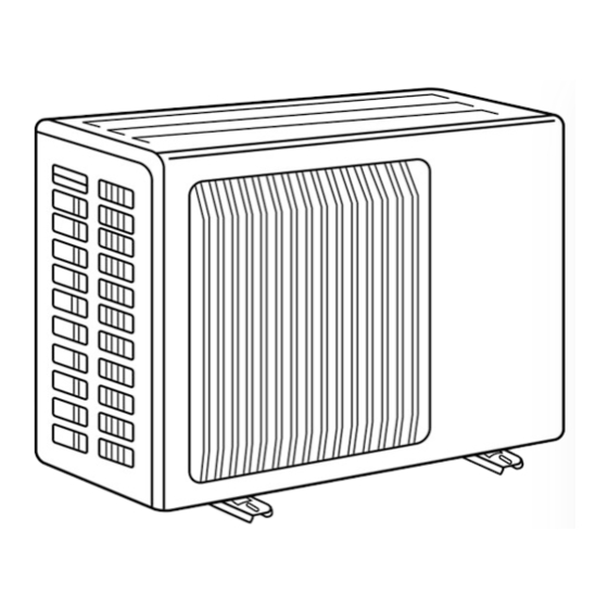
Outdoor unit
[Model names] [Service Ref.]
SUH-1VR.TH
SUH-1VR
SUH-1.6VR.TH
SUH-1.6VR
SUH-1.6VR2.TH
SUH-1.6VR2
SUH-2VR.TH
SUH-2VR
SUH-2.5VR.TH
SUH-2.5VR
SU-1.6NR.TH
SU-1.6NR
SU-2NR.TH
SU-2NR
SU-2.5NR.TH
SU-2.5NR
SU-1VR.TH
SU-1VR
SU-1.6VR.TH
SU-1.6VR
SU-1.6VR2.TH
SU-1.6VR2
SU-2VR.TH
SU-2VR
SU-2VR
SU-2.5VR.TH
SU-2.5VR
OUTDOOR UNIT
• SU-1VR.TH-T, SU-1.6VR2.TH-T and SU-2VR
has been added.
• Instruction of troubleshooting has been added to
pege 29 ans 30.
• Please void
OC282 REVISED EDITION-A
SUH-2VR
SU-1VR.TH-T
SU-1.6VR.TH-T
SU-1.6VR2.TH-T
SU-2VR.TH-T
.TH
SU-2VR
1
SU-2.5VR.TH-T
CONTENTS
1. TECHNICAL CHANGES ···········································2
3. PART NAMES AND FUNCTIONS·····························3
4. SPECIFICATIONS ·····················································4
5. DATA··········································································7
6. OUTLINES AND DIMENSIONS ······························10
7. WIRING DIAGRAM ·················································13
8. REFRIGERANT SYSTEM DIAGRAM ···························19
9. TROUBLESHOOTING ············································28
10. DISASSEMBLY PROCEDURE ·······························32
11. PARTS LIST ····························································48
.TH-T
1
.
REVISED EDITION-B
.TH
SUH-2VR
1
.TH-T
1
No. OC282
.TH
2
Advertisement
Table of Contents

Related Manuals for Mitsubishi Electric SUH-1.6VR2


Summary of Contents for Mitsubishi Electric SUH-1.6VR2
-
Page 1: Table Of Contents
SPLIT-TYPE, HEAT PUMP AIR CONDITIONERS SPLIT-TYPE, AIR CONDITIONERS No. OC282 REVISED EDITION-B TECHNICAL & SERVICE MANUAL Outdoor unit [Model names] [Service Ref.] SUH-1VR.TH SUH-1VR SUH-1.6VR.TH SUH-1.6VR SUH-1.6VR2.TH SUH-1.6VR2 SUH-2VR.TH SUH-2VR SUH-2VR SUH-2VR SUH-2.5VR.TH SUH-2.5VR SU-1.6NR.TH SU-1.6NR SU-2NR.TH SU-2NR SU-2.5NR.TH SU-2.5NR SU-1VR.TH... -
Page 2: Technical Changes
TECHNICAL CHANGES (REVISED EDITION-A) SUH-2VR SUH-2VR OUTDOOR HEAT EXCHANGER has changed. RESTRICTOR VALVE has changed. CAPILLARY TUBE has changed. ({4.0X{2.4XL660) ({3.0X{2.0XL250) COMBINATION OF INDOOR OUTDOOR UNITS Outdoor unit Heat pump type Cooling only type Indoor unit SUH- • .TH SU- • .TH SU- •... -
Page 3: Part Names And Functions
PART NAMES AND FUNCTIONS SUH-1VR.TH SUH-1.6VR.TH SUH-2VR.TH SUH-2.5VR.TH SUH-1.6VR2.TH SUH-2VR SUH-2VR SU-1.6NR.TH SU-2NR.TH SU-2.5NR.TH SU-1VR.TH SU-1.6VR.TH SU-2VR.TH SU-2.5VR.TH SU-1.6VR2.TH SU-2VR SU-1VR.TH-T SU-1.6VR.TH-T SU-2VR.TH-T SU-2.5VR.TH-T SU-1.6VR2.TH-T SU-2VR .TH-T Air outlet Air intake Piping Drain hose Air outlet Air inlet Drain outlet... -
Page 4: Specifications
SPECIFICATIONS Service Ref. SUH-1VR.TH SUH-1.6VR2.TH SUH-1.6VR.TH Power supply Single phase, 220-240V, 50Hz Model RH-174VGHT RH-247VHAT RH-277VHAT Compressor Output 1200 1300 Winding resistance (at 20:) " C-R: 3.30 C-S: 5.80 C-R: 2.13 C-S: 3.91 C-R: 1.80 C-S: 3.00 Model PN6V23-UA RA6V40-EE... - Page 5 SU-1VR.TH SU-1.6VR.TH SU-1.6VR2.TH Service Ref. SU-1VR.TH-T SU-1.6VR.TH-T SU-1.6VR2.TH-T Power supply Single phase, 220-240V, 50Hz Model RH-174VGHT RH-247VHAT RH-277VHAT Compressor Output 1200 1300 Winding resistance (at 20:) " C-R: 3.30 C-S: 5.80 C-R: 2.13 C-S: 3.91 C-R: 1.80 C-S: 3.00 Model RA6V23-HC RA6V40-EE Outdoor...
- Page 6 SU-2.5NR.TH Service Ref. SU-1.6NR.TH SU-2NR.TH Power supply Single phase, 220V, 60Hz Model RH-207NHDT NH-33NCDT NH-38NBDT Compressor Output 1000 1500 1700 Winding resistance (at 20:) " C-R: 1.68 C-S: 2.78 C-R: 0.92 C-S: 1.93 C-R: 0.83 C-S: 1.83 Model RA6V40-EE RA6V50-OF RA6V60-AB Outdoor WHT-BLK : 81...
-
Page 7: Data
DATA NOISE CRITERION CURVES <50Hz> <50Hz> SUH-1VR.TH SUH-1.6VR.TH SPL(dB) LINE SPL(dB) LINE SUH-1.6VR2.TH NC-70 NC-70 NC-60 NC-60 NC-50 NC-50 NC-40 NC-40 NC-30 NC-30 APPROXIMATE APPROXIMATE THRESHOLD OF THRESHOLD OF HEARING FOR NC-20 NC-20 HEARING FOR CONTINUOUS CONTINUOUS NOISE NOISE 1000... - Page 8 <50Hz> <50Hz> SU-1VR.TH SU-1.6VR.TH SPL(dB) LINE SPL(dB) LINE SU-1.6VR2.TH SU-1VR.TH-T SU-1.6VR.TH-T SU-1.6VR2.TH-T NC-70 NC-70 NC-60 NC-60 NC-50 NC-50 NC-40 NC-40 NC-30 NC-30 APPROXIMATE APPROXIMATE THRESHOLD OF THRESHOLD OF HEARING FOR NC-20 HEARING FOR NC-20 CONTINUOUS CONTINUOUS NOISE NOISE 1000 2000 4000 8000 1000...
- Page 9 <50Hz> <60Hz> SU-2.5VR.TH SU-2.5NR.TH NOTCH SPL(dB) LINE NOTCH SPL(dB) LINE SU-2.5VR.TH-T NC-70 NC-70 NC-60 NC-60 NC-50 NC-50 NC-40 NC-40 NC-30 NC-30 APPROXIMATE APPROXIMATE THRESHOLD OF THRESHOLD OF HEARING FOR HEARING FOR NC-20 NC-20 CONTINUOUS CONTINUOUS NOISE NOISE 1000 2000 4000 8000 1000 2000...
-
Page 10: Outlines And Dimensions
OUTLINES AND DIMENSIONS SUH-1VR.TH Unit: mm SU-1VR.TH SU-1VR.TH-T REQUIRED SPACE Outdoor unit Air in Air in Drainage 3holes [33 Air out Service panel Liquid refrigerant pipe joint Refrigerant pipe (flared) [6.35 Gas refrigerant pipe joint Refrigerant pipe (flared) [9.52... - Page 11 SUH-1.6VR.TH SUH-2VR.TH SUH-1.6VR2.TH SUH-2VR SUH-2VR SU-1.6NR.TH SU-2NR.TH SU-2.5NR.TH SU-1.6VR.TH SU-2VR.TH SU-2.5VR.TH SU-1.6VR2.TH SU-2VR SU-1.6VR.TH-T SU-2VR.TH-T SU-2.5VR.TH-T SU-1.6VR2.TH-T SU-2VR .TH-T Unit: mm If the right/left sides or back side is vacant,the Drainage front has only to be 50cm 3holes 16.2 unobstructed.
- Page 12 SUH-2.5VR.TH...
-
Page 13: Wiring Diagram
WIRING DIAGRAM SUH-1VR.TH 21S4 RT61 CN611 CN721 CN720 CN730 12VDC SR61 TAB21 220-240V~ 2 TRANS CN711 TAB20 DEICER P.C. BOARD WHT NO GRN/YLW SYMBOL NAME SYMBOL NAME SYMBOL NAME COMPRESSOR CAPACITOR COMPRESSOR (INNER THERMOSTAT) TERMINAL BLOCK FAN MOTOR CAPACITOR FAN MOTOR (INNER THERMOSTAT) 4-WAY VALVE RELAY DSAR SURGE ABSORBER... - Page 14 SUH-1.6VR.TH SUH-2VR.TH SUH-1.6VR2.TH SUH-2VR SUH-2VR RT61 21S4 CN711 1 2 3 CN661 CN721 CN730 12VDC IC881 220-240V TRANS TAB20 DEICER 52C1 P.C. BOARD 52C1 L1/1 T1/2 L3/5 T3/6 SYMBOL NAME SYMBOL NAME SYMBOL NAME COMPRESSOR CAPACITOR RT61 DEFROST THERMISTOR IC881 DC/DC CONVERTER...
- Page 15 SUH-2.5VR.TH RT61 21S4 CN711 1 2 3 CN661 CN721 CN730 12VDC IC881 220-240V~ 26F1 TRANS TAB20 DEICER 52C1 P.C. BOARD 52C1 L1/1 T1/2 L3/5 T3/6 SYMBOL NAME SYMBOL NAME SYMBOL NAME COMPRESSOR CAPACITOR RT61 DEFROST THERMISTOR FAN MOTOR RELAY THERMAL REED SWITCH FAN MOTOR CAPACITOR SR61 SOLID STATE RELAY...
- Page 16 SU-1VR.TH SU-1VR.TH-T 220-240V~ 220-240V~ L1/1 T1/2 L3/5 T3/6 SYMBOL NAME SYMBOL NAME SYMBOL NAME COMPRESSOR CONTACTOR SURGE ABSORBER COMPRESSOR (INNER THERMOSTAT) COMPRESSOR CAPACITOR FAN MOTOR (INNER THERMOSTAT) FAN MOTOR CAPACITOR TERMINAL BLOCK sleeve NOTE :1. Use copper conductors only (For field wiring). 2.
- Page 17 SU-1.6NR.TH SU-2NR.TH 220V, 60Hz 220V, 60Hz L1/1 T1/2 L3/5 T3/6 SYMBOL NAME SYMBOL NAME SYMBOL NAME COMPRESSOR SURGE ABSORBER COMPRESSOR CONTACTOR (INNER THERMOSTAT) FAN MOTOR COMPRESSOR CAPACITOR THERMAL SWITCH (INNER THERMOSTAT) FAN MOTOR CAPACITOR TERMINAL BLOCK FUSE(2A) TERMINAL BLOCK SU-2.5NR.TH 220V, 60Hz RED 8 220V, 60Hz...
- Page 18 SU-1.6VR.TH SU-1.6VR2.TH 220-240V,50Hz SU-2VR.TH SU-2VR 220-240V,50Hz SU-1.6VR.TH-T SU-1.6VR2.TH-T SU-2VR.TH-T SU-2VR .TH-T L1/1 T1/2 L3/5 T3/6 SYMBOL NAME SYMBOL NAME SYMBOL NAME COMPRESSOR SURGE ABSORBER COMPRESSOR CONTACTOR (INNER THERMOSTAT) FAN MOTOR COMPRESSOR CAPACITOR (INNER THERMOSTAT) FAN MOTOR CAPACITOR TERMINAL BLOCK FUSE(2A) TERMINAL BLOCK SU-2.5VR.TH 220-240V,50Hz...
-
Page 19: Refrigerant System Diagram
Accumulator Capillary tube Compressor ({3.0x{1.6xL550)w1 ({3.0x{1.8xL550)w2 Defrost thermistor Capillary tube Flared connection RT61 ({3.0x{1.8xL330)w1 (#100) ({3.0x{1.6xL420)w2 w1 SUH-1.6VR.TH Strainer w2 SUH-1.6VR2.TH Stop valve Refrigerant pipe (Option) [6.35 Restrictor valve (with heat insulator) Refrigerant flow in cooling Refrigerant flow in heating... - Page 20 SUH-2VR.TH SUH-2VR SUH-2VR Strainer 1 Refrigerant pipe [15.88 Reversing (#100) valve (Option) (with heat insulator) Muffler Stop valve (with service port) Outdoor Flared connection heat exchanger Discharge Pressure Regulator Capillary Accumulator tube Compressor ({3.0X{1.6XL860)X2 Defrost thermistor RT61 Capillary tube Flared connection ({4.0X{2.4XL660)···2VR (#100) ({3.0X{2.0XL250)···2VR...
- Page 21 SU-1.6NR.TH Refrigerant pipe [12.7 (Option) (with heat insulator) Stop valve (with service port) Outdoor Flared connection heat exchanger Dis pressure regulator Compressor Capillary tube Flared connection ([3.0x[1.8xL100) (#100) Strainer Capillary tube Stop valve Refrigerant pipe ([3.0x[1.8xL550) (Option) [6.35 (with heat insulator) Refrigerant flow SU-2NR.TH Refrigerant pipe [15.88...
- Page 22 SU-2.5NR.TH Refrigerant pipe [15.88 (Option) (with heat insulator) Stop valve (with service port) Outdoor Flared connection heat exchanger Accumulator Compressor Dis pressure regulator Capillary tube Flared connection ([3.0x[2.0xL100) (#100) Strainer Capillary tube Stop valve Refrigerant pipe ([3.0x[2.0xL600) (Option) [9.52 (with heat insulator) Refrigerant flow SU-1VR.TH SU-1VR.TH -T...
- Page 23 SU-1.6VR.TH SU-1.6VR2.TH Refrigerant pipe [12.7 SU-1.6VR.TH-T (Option) (with heat insulator) SU-1.6VR2.TH-T Stop valve (with service port) Outdoor Flared connection heat exchanger Compressor Flared connection (#100) Strainer Capillary tube Stop valve Refrigerant pipe ([3.0x[1.8xL800)···SU-1.6VR.TH(-T) (Option) [6.35 ([3.0x[1.8xL500)···SU-1.6VR2.TH(-T) (with heat insulator) Refrigerant flow SU-2VR.TH SU-2VR Refrigerant pipe [15.88...
- Page 24 SU-2.5VR.TH SU-2.5VR.TH-T Refrigerant pipe [15.88 (Option) (with heat insulator) Stop valve (with service port) Outdoor Flared connection heat exchanger Accumulator Compressor Dis pressure regulator Capillary tube Flared connection ([3.0x[2.0xL100) (#100) Strainer Capillary tube Stop valve Refrigerant pipe ([3.0x[2.0xL700) (Option) [9.52 (with heat insulator) Refrigerant flow...
- Page 25 MAX. REFRIGERANT PIPING LENGTH & MAX. HEIGHT DIFFERENCE Service Ref. Length : m(ft) Piping size O.D. : mm (in.) Indoor unit Outdoor unit Liquid SEH-1.6AR.TH SEH-1.6AR SUH-1.6VR.TH SUH-1.6VR2.TH SE-1.6AR.TH SE-1.6AR SU-1.6NR.TH SU-1.6VR.TH SU-1.6VR2.TH {12.7(1/2) SE-1.6AR.TH-T SE-1.6AR .TH-T SU-1.6VR.TH-T SU-1.6VR2.TH-T {6.35(1/4) SEH-2AR.TH...
- Page 26 MAX. REFRIGERANT PIPING LENGTH & MAX. HEIGHT DIFFERENCE Models Length : m(ft) Piping size O.D. : mm (in.) Indoor unit Outdoor unit Liquid SLH-1AR.TH SUH-1VR.TH {9.52(3/8) SL-1AR.TH SU-1VR.TH SU-1VR.TH-T SL-1AR.TH-T SLH-1.6AR.TH SUH-1.6VR2.TH 20(66) SL-1.6AR.TH SU-1.6VR2.TH {12.7(1/2) {6.35(1/4) SL-1.6AR.TH-T SU-1.6VR2.TH-T SLH-2AR.TH SUH-2VR .TH, SUH-2VR SU-2VR {15.88(5/8) SL-2AR.TH SL-2AR.TH-T SU-2VR .TH-T...
-
Page 27: Evacuation Procedures
EVACUATION PROCEDURES Connect the refrigerant pipes (both the liquid and gas pipes) between the indoor and the outdoor units. Remove the service port cap of the stop/ball valve. (The stop/ball valve will not work in its initial state fresh out of the factory (totally closed with cap on).) Connect the gauge manifold valve and the vacuum pump to the service port of the stop/ball valve . -
Page 28: Troubleshooting
TROUBLESHOOTING 9-1. Test point of P.C. board •Deicer P.C. board SUH-1VR.TH SUH-1.6VR.TH SUH-1.6VR2.TH SUH-2VR.TH SUH-2VR SUH-2VR SUH-2.5VR.TH R601 5~10V DC INPUT Outdoor fan motor Solenoid coil 220-240V AC 220-240V AC 220-240V AC Defrost thermistor(RT61) DEICER P.C. BOARD Fuse 2A/250V Defrost interval... - Page 29 Check of deicer P.C. board and outdoor fan motor SUH-1VR.TH SUH-1.6VR.TH Operation lamp blinks once in a fixed period. SUH-1.6VR2.TH SUH-2VR.TH SUH-2VR Error was found in the signal transmitted or received between the indoor and outdoor units. SUH-2VR SUH-2.5VR.TH Is the connecting wire between...
- Page 30 From the preceding page. Indoor unit operates, while outdoor unit does not. Compressor does not operate. Fan motor does not operate. Is the connecting wire between the Is the connecting wire between the indoor and outdoor units connected indoor and outdoor units connected properly? properly? Connection is defective.
-
Page 31: Trouble Criterion Of Main Parts
9-2. Trouble criterion of main parts SUH-1VR.TH SUH-1.6VR.TH SUH-2VR.TH SUH-2.5VR.TH SUH-1.6VR2.TH SUH-2VR SUH-2VR SU-1.6NR.TH SU-2NR.TH SU-2.5NR.TH SU-1VR.TH SU-1.6VR.TH SU-2VR.TH SU-2.5VR.TH SU-1.6VR2.TH SU-2VR SU-1VR.TH-T SU-1.6VR.TH-T SU-2VR.TH-T SU-2.5VR.TH-T SU-1.6VR2.TH-T SU-2VR .TH-T Part name Check method and criterion Figure Measure the resistance with a tester. -
Page 32: Disassembly Procedure
DISASSEMBLY PROCEDURE SUH-1VR.TH OPERATING PROCEDURE PHOTOS 1. Removing the cabinet Photo 1 (1) Remove the screws for the top panel. Screws for front panel and motor support (2) Remove the screw for the service panel. (3) Remove the screws for the cabinet. (4) Remove the screws for the front panel and motor support. - Page 33 OPERATING PROCEDURE PHOTOS 3. Removing the propeller fan and the outdoor fan Photo 5 motor Lead clamps (1) Remove the cabinet. (Refer to 1.) Set screws for (2) Remove the propeller fan nut. outdoor fan motor Outdoor (3) Remove the propeller fan. fan motor Propeller fan connector...
- Page 34 SUH-1.6VR2.TH OPERATING PROCEDURE PHOTOS 1. Removing the front panel Photo 1 (1) Remove the screws of the front panel. (2) Hold the bottom of the front panel on the both side to remove the cabinet. Photo 2 Screws Service panel Screws 2.
- Page 35 PHOTOS OPERATING PROCEDURE Photo 4 3. Removing the outdoor fan motor Set screws for (1) Remove the front panel. (Refer to 1) outdoor fan motor propeller fan (2) Unconnect the connector remove the clamp of fan motor lead wire. (3) Remove the propeller nut and remove the propeller fan. (4) Remove screws fixing the fan motor.
- Page 36 SUH-2VR SUH-2VR OPERATING PROCEDURE PHOTOS 1. Removing the front panel Photo 1 (1) Remove the screws of the front panel. (2) Hold the bottom of the front panel on the both side to remove the cabinet. Photo 2 Screws Service panel Screws 2.
- Page 37 PHOTOS OPERATING PROCEDURE Photo 4 3. Removing the outdoor fan motor Set screws for (1) Remove the front panel. (Refer to 1) outdoor fan motor (2) Unconnect the connector remove the clamp of fan motor propeller fan lead wire. (3) Remove the propeller nut and remove the propeller fan. (4) Remove screws fixing the fan motor.
- Page 38 SUH-2.5VR.TH OPERATING PROCEDURE PHOTOS 1. Removing the electrical parts Photo 1 ( 1 ) Remove the 5 screws and the top panel. ( 3 screws in Screws front and 2 screws in rear ) ( 2 ) Remove the screw of the cover panel. To remove the Top panel cover panel, pull it toward you and unhook the catch- es from the side panel.
- Page 39 OPERATING PROCEDURE PHOTOS 3. Removing the heat exchanger and the compressor Photo 4 ( 1 ) Remove the rear panel (2 screws in front, 1 screw on Screws the side, 3 screws in the rear). Remove the valve bed, and open the rear panel to the rear to remove. NOTE : All panels are fixed by catches, and must be removed by shifting up and down.
- Page 40 SU-1VR.TH SU-1VR.TH-T OPERATING PROCEDURE PHOTOS 1. Removing the cabinet Photo 1 (1) Remove the screws for the top panel. Screws for front panel and motor support (2) Remove the screw for the service panel. (3) Remove the screws for the cabinet. (4) Remove the screws for the front panel and motor support.
- Page 41 OPERATING PROCEDURE PHOTOS 3. Removing the propeller fan and the outdoor fan Photo 5 motor Lead clamp (1) Remove the cabinet. (Refer to 1.) Set screws for (2) Remove the propeller fan nut. outdoor fan motor Outdoor fan motor (3) Remove the propeller fan. connector Propeller fan NOTE : Loose the propeller fan in the rotating direction for...
- Page 42 SU-1.6VR2.TH SU-1.6VR2.TH-T OPERATING PROCEDURE PHOTOS 1. Removing the cabinet Photo 1 (1) Remove the screws of the cabinet. (2) Hold the bottom of the cabinet on the both side to remove the cabinet. Photo 2 Screws Service panel Screws 2. Removing the electrical parts (1) Remove the cabinet.(Refer to 1) Photo 3 (2) Remove the following parts.
- Page 43 OPERATING PROCEDURE PHOTOS 3. Removing the propeller fan and the outdoor fan Photo 4 motor Lead clamp (1) Remove the cabinet. (Refer to 1.) Set screws for (2) Remove the propeller fan nut. outdoor fan motor Outdoor (3) Remove the propeller fan. fan motor Propeller fan NOTE : Loose the propeller fan in the rotating direction for...
- Page 44 SU-2VR SU-2VR .TH-T OPERATING PROCEDURE PHOTOS 1. Removing the cabinet Photo 1 (1) Remove the screws of the cabinet. (2) Hold the bottom of the cabinet on the both side to remove the cabinet. Photo 2 Screws Service panel Screws 2.
- Page 45 OPERATING PROCEDURE PHOTOS 3. Removing the propeller fan and the outdoor fan Photo 4 motor Lead clamp (1) Remove the cabinet. (Refer to 1.) Set screws for (2) Remove the propeller fan nut. outdoor fan motor Outdoor (3) Remove the propeller fan. fan motor Propeller fan NOTE : Loose the propeller fan in the rotating direction for...
- Page 46 SU-1.6NR.TH SU-2NR.TH SU-2.5NR.TH SU-1.6VR.TH SU-2VR.TH SU-2.5VR.TH SU-1.6VR.TH-T SU-2VR.TH-T SU-2.5VR.TH-T OPERATING PROCEDURE PHOTOS 1. Removing the cabinet Photo 1 (1) Remove the screws of the cabinet. (2) Hold the bottom of the cabinet on the both side to remove the cabinet. Photo 2 Screws Service...
- Page 47 OPERATING PROCEDURE PHOTOS Photo 4 3. Removing the outdoor fan motor Fan motor cable Connector (1) Remove the cabinet. (Refer to 1) (2) Unconnect the connector remove the clamp of fan motor lead wire. (3) Remove the propeller nut and remove the propeller. (4) Remove screws fixing the fan motor.
-
Page 48: Parts List
PARTS LIST OUTDOOR UNIT STRUCTURAL PARTS SUH-1VR.TH SU-1VR.TH SU-1VR.TH-T... - Page 49 Part numbers that are circled are not shown in the illustration. Price Q'ty/set Wiring Recom- Parts No. Specification Remarks Parts name SUH-1 SU-1 Diagram mended Unit Amount (Drawing No.) VR.TH Symbol Q'ty VR.TH VR.TH-T E02 440 630 OUTDOOR HEAT EXCHANGER E02 336 630 OUTDOOR HEAT EXCHANGER E02 336 232...
- Page 50 OUTDOOR UNIT STRUCTURAL PARTS SUH-1.6VR.TH SU-1.6VR.TH SU-1.6VR.TH-T SUH-1.6VR2.TH SU-1.6VR2.TH SU-1.6VR2.TH-T 25 24 Price Q'ty/set Wiring Recom- Parts No. Specification Remarks Parts name SUH-1.6 SU-1.6 Diagram mended Unit Amount (Drawing No.) VR.TH VR2.TH Symbol Q'ty VR.TH VR2.TH VR.TH-T VR2.TH-T E02 141 521...
- Page 51 Part numbers that are circled are not shown in the illustration. Price Q'ty/set Wiring Recom- Parts No. Specification Remarks Parts name SUH-1.6 SU-1.6 Diagram mended Unit Amount (Drawing No.) VR.TH VR2.TH Symbol Q'ty VR.TH VR2.TH VR.TH-T VR2.TH-T E02 134 932 ACCUMULATOR E07 113 932 ACCUMULATOR...
- Page 52 OUTDOOR UNIT STRUCTURAL PARTS SUH-2VR.TH SU-2VR.TH SU-2VR.TH-T SUH-2VR SU-2VR SU-2VR .TH-T SUH-2VR 25 24 Price Q'ty/set Wiring Recom- Parts No. Specification Remarks Parts name SUH-2 SU-2 Diagram mended Unit Amount (Drawing No.) VR.TH Symbol Q'ty VR.TH VR .TH VR VR.TH-T .TH-T E02 141 521 GRILLE (OUT)
- Page 53 Part numbers that are circled are not shown in the illustration. Price Q'ty/set Wiring Recom- Parts No. Specification Remarks Parts name SUH-2 SU-2 Diagram mended Unit Amount (Drawing No.) VR.TH Symbol Q'ty VR.TH VR .TH VR VR.TH-T .TH-T E02 258 932 ACCUMULATOR E07 058 932 ACCUMULATOR...
- Page 54 OUTDOOR UNIT STRUCTURAL PARTS SUH-2.5VR.TH...
- Page 55 Part number that are circled is not shown in the illustration. Price Wiring Recom- Q'ty/set Parts No. Specification Remarks Parts name Diagram mended Unit Amount (Drawing No.) Symbol Q'ty SUH-2.5VR.TH E02 214 249 LEFT SIDE PANEL E02 214 232 FRONT PANEL E07 001 009 HANDEL E02 214 521...
- Page 56 OUTDOOR UNIT STRUCTURAL PARTS SU-2.5VR.TH SU-2.5VR.TH-T 9 10...
- Page 57 Part number that are circled is not shown in the illustration. Price Q'ty/set Wiring Recom- Parts No. Specification Remarks Parts name Diagram mended SU-2.5VR.TH Unit Amount (Drawing No.) SU-2.5VR.TH-T Symbol Q'ty E02 141 521 GRILLE(OUT) E02 141 232 CABINET E02 147 630 OUTDOOR HEAT EXCHANGER E02 141 501 PROPELLER FAN...
- Page 58 OUTDOOR UNIT STRUCTURAL PARTS SU-1.6NR.TH SU-2NR.TH SU-2.5NR.TH 9 10 Price Q'ty/set Wiring Recom- Parts No. Specification Remarks Parts name SU-1.6 SU-2 SU-2.5 Diagram mended Unit Amount (Drawing No.) Symbol Q'ty NR.TH E02 141 521 GRILLE(OUT) E02 141 232 CABINET E02 141 630 OUTDOOR HEAT EXCHANGER E02 138 630 OUTDOOR HEAT EXCHANGER...
- Page 59 Part number that are circled is not shown in the illustration. Price Q'ty/set Wiring Recom- Parts No. Parts name Specification Remarks SU-1.6 SU-2 SU-2.5 Diagram mended Unit Amount (Drawing No.) Symbol Q'ty NR.TH E02 140 290 BASE E02 138 290 BASE E02 176 290 BASE...
- Page 60 HEAD OFFICE : MITSUBISHI DENKI BLDG., 2-2-3, MARUNOUCHI, CHIYODA-KU, TOKYO 100-8310, JAPAN CCopyright 2002 MITSUBISHI ELECTRIC ENGINEERING CO., LTD Distributed in Jan. 2003 No.OC282 REVISED EDITION-B PDF 341. Distributed in Sep. 2002 No.OC282 REVISED EDITION-A PDF 462 Reprinted in Jul. 2002 No.OC282 10 New publication, effective Jan.
Need help?
Do you have a question about the SUH-1.6VR2 and is the answer not in the manual?
Questions and answers