Advertisement
Table of Contents
SPLIT-TYPE, AIR CONDITIONERS
SERVICE MANUAL
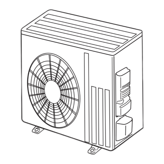
Outdoor unit
[Model Name]
SUZ-KA18NA2
SUZ-KA18NAH2
SUZ-KA24NA
SUZ-KA24NAH2
SUZ-KA30NA
SUZ-KA30NAH2
SUZ-KA36NA
SUZ-KA36NAH2
SUZ-KA18NA(H)2.TH
R410A
[Service Ref.]
SUZ-KA18NA2.TH
SUZ-KA18NAH2.TH
SUZ-KA24NA2.TH
SUZ-KA24NAH2.TH
SUZ-KA30NA2.TH
SUZ-KA30NAH2.TH
SUZ-KA36NA2.TH
SUZ-KA36NAH2.TH
REVISED EDITION-D
Revision:
• Some descriptions have
been modified in REVISED
EDITION-D.
OCH688C is void.
Note:
• This manual describes service
data of the outdoor units only.
CONTENTS
1. COMBINATION OF INDOOR AND
OUTDOOR UNITS ···································· 2
2. PART NAMES AND FUNCTIONS ············ 2
3. SPECIFICATION ······································· 3
4. OUTLINES AND DIMENSIONS ················ 4
5. WIRING DIAGRAM ··································· 5
6. REFRIGERANT SYSTEM DIAGRAM ······ 9
7. DATA ······················································· 11
8. ACTUATOR CONTROL ·························· 14
9. SERVICE FUNCTIONS ··························· 15
10. TROUBLESHOOTING ···························· 15
11. FUNCTION SETTING ····························· 32
12. DISASSEMBLY INSTRUCTIONS ··········· 35
PARTS CATALOG (OCB688)
June 2021
No. OCH688
Advertisement
Table of Contents


Need help?
Do you have a question about the SUZ-KA18NA2 and is the answer not in the manual?
Questions and answers