Advertisement
Table of Contents
SPLIT-TYPE, AIR CONDITIONERS
SERVICE MANUAL
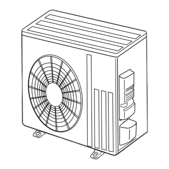
Outdoor unit
[Model Name]
SUZ-KA18NA2
SUZ-KA18NAH2
SUZ-KA24NA
SUZ-KA24NAH2
SUZ-KA30NA
SUZ-KA30NAH2
SUZ-KA36NA
SUZ-KA36NAH2
SUZ-KA18NA(H)2.TH
R410A
[Service Ref.]
SUZ-KA18NA2.TH
SUZ-KA18NAH2.TH
SUZ-KA24NA2.TH
SUZ-KA24NAH2.TH
SUZ-KA30NA2.TH
SUZ-KA30NAH2.TH
SUZ-KA36NA2.TH
SUZ-KA36NAH2.TH
REVISED EDITION-D
Revision:
• Some descriptions have
been modified in REVISED
EDITION-D.
OCH688C is void.
Note:
• This manual describes service
data of the outdoor units only.
CONTENTS
1. COMBINATION OF INDOOR AND
OUTDOOR UNITS ···································· 2
2. PART NAMES AND FUNCTIONS ············ 2
3. SPECIFICATION ······································· 3
4. OUTLINES AND DIMENSIONS ················ 4
5. WIRING DIAGRAM ··································· 5
6. REFRIGERANT SYSTEM DIAGRAM ······ 9
7. DATA ······················································· 11
8. ACTUATOR CONTROL ·························· 14
9. SERVICE FUNCTIONS ··························· 15
10. TROUBLESHOOTING ···························· 15
11. FUNCTION SETTING ····························· 32
12. DISASSEMBLY INSTRUCTIONS ··········· 35
PARTS CATALOG (OCB688)
June 2021
No. OCH688
Advertisement
Table of Contents

Related Manuals for Mitsubishi Electric SUZ-KA24NA


Summarization of Contents
SPECIFICATION
OPERATING RANGE (1) POWER SUPPLY
Details power supply specifications for outdoor units, including guaranteed voltage ranges.
OUTLINES AND DIMENSIONS
REQUIRED SPACE
Specifies minimum clearance dimensions around the outdoor unit for proper operation and servicing.
MAX. REFRIGERANT PIPING LENGTH and MAX. HEIGHT DIFFERENCE
ADDITIONAL REFRIGERANT CHARGE (R410A: oz.)
Provides guidance on calculating additional refrigerant charge based on piping length beyond a standard limit.
DATA
STANDARD OPERATION DATA
Lists key operational data such as capacity, input, pressures, and temperatures for various unit combinations.
ACTUATOR CONTROL
RELATION BETWEEN MAIN SENSOR AND ACTUATOR
Details how sensors correlate with specific actuators (Compressor, LEV, Fan, R.V. coil, Indoor fan).
SERVICE FUNCTIONS
CHANGE IN DEFROST SETTING
Describes how to adjust the defrost finish temperature by modifying a jumper setting on the P.C. board.
TROUBLESHOOTING
CAUTIONS ON TROUBLESHOOTING
Outlines safety precautions and preliminary checks before commencing troubleshooting procedures.
HOW TO PROCEED "SELF-DIAGNOSIS"
10-3-1. Self-diagnosis
Step-by-step guide to recall and view the latest error history using the remote controller's self-diagnosis function.
TROUBLESHOOTING FLOW
How to check inverter/compressor
A flowchart guiding the diagnosis of inverter and compressor issues, including voltage checks.
N Check the defrost heater (base pan heater)
Check of outdoor refrigerant circuit
Procedures to check for operation stops during pump down and issues related to refrigerant gas amount or leaks.
10-6. TEST POINT DIAGRAM AND VOLTAGE
Inverter P.C. board
Diagrams showing test points, voltage measurements, and component locations on the inverter P.C. board.
FUNCTION SETTING
UNIT FUNCTION SETTING BY THE REMOTE CONTROLLER
Guide to setting various unit functions using the wired remote controller, including unit number and mode selection.
DISASSEMBLY INSTRUCTIONS
Removing the cabinet
Step-by-step instructions for safely removing the outer cabinet and its panels for access to internal components.
Need help?
Do you have a question about the SUZ-KA24NA and is the answer not in the manual?
Questions and answers