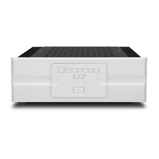
Table of Contents
Advertisement
Advertisement
Table of Contents

Summary of Contents for Bryston 3B3
- Page 1 & 4B Owner’s Manual...
-
Page 2: Important Safety Instructions
As of 2006-02-22 Bryston will only warranty Bryston products purchased through authorized Bryston dealers. Bryston products with a date code of 0608 or higher (date code format is “yyww”, where “yy” is the two least significant digits of the year and “ww” is the week of the year) must be accompanied by a copy of the bill-of-sale from a Bryston authorized dealer to qualify for warranty service. -
Page 3: Table Of Contents
Table of Contents Important Safety Instructions ........General................. Welcome ..............Description ............Features ..............Shipping Box and Packing Material ...... Installation and Usage ..........Ventilation ............. Connecting to A/C Power ........Connecting to Loudspeakers: 2 Channel Mode ... Connecting Audio Inputs ........Balanced vs. -
Page 4: Installation And Usage
Installation and Usage Ventilation BLACK Never operate the Connecting to A/C Power Connecting to Loudspeakers: 2 Channel Mode... -
Page 5: Connecting Audio Inputs
& 3B Connecting Audio Inputs External Control Voltage Balanced vs. Single Ended Input Power Conditioners Note: REMOTE POWER TURN-ON PLUG-IN CONNECTOR Insert stripped ends of insulated wires revealing approx. 1/4" of bare, stranded copper wire between 24 and 12 AWG (.5mm to 2mm dia.) into open elevator style wire clamps &... -
Page 6: Connecting To Loudspeakers: Bridged Mode
Connecting to Loudspeakers: Bridged Mode • • • BLACK • • • From Pre-Amp CAN ICES-3 (B)/NMB-3(B) CAN ICES-3 (B)/NMB-3(B) GAIN GAIN MODE INPUTS INPUTS This device complies with FCC This device complies with FCC Part 15, subpart B Part 15, subpart B 29dB 29 9 9 9 9 9 9 9 9 9 9 9 9 d d d d d d d d d d d d d d d d d d d d d d d d d d d d d d d d d d d d d d d d d d d d d d d d d d d d d d d d d d d d d d d d d d d d d d d d d d d d d d d d d d d d d d d d d d d d d d d d d d d d d d d d d d d d d d d d d d d d d d d d d d d d d d d d d d d d d d d d d d d d d d d d d d d d d d d d d d d d d d d d d d d d d d d d d d d d d d d d d d d d d d d d d d d d d d d d d d d d d d d d d d d d d d d d d d d d d d d d d d d d d d d d d d d d d d d d d d d d d d d d d d d d d d d d d d d d d d d d d d d d d d d d d d d d d d d d d d d d d d d d d d d d d d d d d d d d d d d d d d d d d d d d d d d d d d d d d d d d d d d d d d d d d d d d d d d d d d d d d d d d d d d d d d d d d d d d d d d d d d d d d B INDIVIDUAL... -
Page 7: Front Panel
& 3B Front Panel CLIPPING 1. Power/Standby Switch: 2. LED Indicators: Unlit THERMAL SHUTDOWN Green Flashing Orange POWER UP SEQUENCE UNLIT LED... -
Page 8: Rear Panel
CAN ICES-3 (B)/NMB-3(B) GAIN MODE INPUTS This device complies with FCC 29dB INDIVIDUAL BALANCED Part 15, subpart B CAUTION CAUTION RISK OF ELECTRIC SHOCK - DO NOT OPEN 23dB BRIDGED SINGLE PRECAUTION ATTENTION PETERBOROUGH, ONTARIO, CANADA ENDED MADE IN/FABRIQUE AU CANADA RISQUE DE CHOC ELECTRIQUE - NE PAS OUVRIR BALANCED BALANCED... - Page 9 & 3B 6. Channel Level Attenuators (PRO 9. A/C Power Input: ONLY): 7. Output Binding Posts: 10. Remote Power Up: 11. Power Status Indicator: 8. Master Circuit Breaker: 12. Data Plate: 4B3-17-SIL-120 ~120V 60Hz 1000W Serial No: 4B3-000000 Date: 1530 REV: 1234...
- Page 10 Specifications Specifications Power Output 200W Power Output 300W Per Channel Per Channel Gain Gain Sensitivity 100W Sensitivity 100W 200W 300W 100W 100W 200W 300W Input Input Impedance Impedance THD+N THD+N Noise (input Noise (input shorted, 20Hz- shorted, 20Hz- Slew Rate Slew Rate Bandwidth Bandwidth...
-
Page 11: Dimensions
& 3B Dimensions... - Page 12 300043 2016-01-19...


Need help?
Do you have a question about the 3B3 and is the answer not in the manual?
Questions and answers