Advertisement
Advertisement

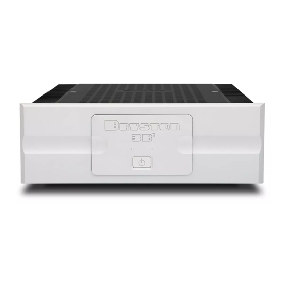
Summary of Contents for Bryston 3B3
- Page 1 & 4B Amplifier Owner’s Manual...
-
Page 2: Important Safety Instructions
As of 2006-02-22 Bryston will only warranty Bryston products purchased through authorized Bryston dealers. Bryston products with a date code of 0608 or higher (date code format is “yyww”, where “yy” is the two least significant digits of the year and “ww” is the week of the year) must be accompanied by a copy of the bill-of-sale from a Bryston authorized dealer to qualify for warranty service. -
Page 3: Table Of Contents
19 inch wide rack mountable dress panels with a black anodized front finish and also include Welcome individual channel trims located on the rear panel. Thank you for your purchase of a Bryston 3B or 4B (Cubed) amplifier! Decades of ongoing Features... -
Page 4: Installation And Usage
Ventilation The RED binding post is connected to the channel output. Connect this post to the (+) terminal on the Bryston has deliberately chosen to omit fans from loudspeaker. our amplifiers in an effort to minimize the noise level in your listening environment. Instead, we use... -
Page 5: Connecting Audio Inputs
22 to 18 gauge between the source both available and can be selected using the Input device and the Bryston Cubed series amplifier. The Select switch on the rear panel of the amplifier. appropriate mating connector is supplied with each Balanced vs. -
Page 6: Connecting To Loudspeakers: Bridged Mode
Connecting to Loudspeakers: Connections are only to be made in areas highlighted in the diagram below. Bridged Mode “Bridged mode” connects the individual channels • Only Channel #1 input is used. in series to form a single amplifier channel. The •... -
Page 7: Front Panel
& 3B Amplifiers Front Panel CLIPPING (flashing red) Clipping occurs when the channel output level 1. Power/Standby Switch: no longer can follow the level increase at the The front panel features a push-on/push-off input (over driven input condition). When a type latching power switch used to apply or channel is driven into clipping, the channel remove A/C line power to the SoftStart circuitry. -
Page 8: Rear Panel
CAN ICES-3 (B)/NMB-3(B) GAIN MODE INPUTS This device complies with FCC 29dB INDIVIDUAL BALANCED Part 15, subpart B CAUTION CAUTION RISK OF ELECTRIC SHOCK - DO NOT OPEN 23dB BRIDGED SINGLE PRECAUTION ATTENTION PETERBOROUGH, ONTARIO, CANADA ENDED MADE IN/FABRIQUE AU CANADA RISQUE DE CHOC ELECTRIQUE - NE PAS OUVRIR BALANCED BALANCED... - Page 9 & 3B Amplifiers 6. Channel Level Attenuators (PRO 9. A/C Power Input: ONLY): An IEC-320 C14 power inlet provides for connection of an IEC-320 C13 equipped power The level control will attenuate the input signal cord. Before connecting the power cord to the level from 0dB through -14dB.
- Page 10 Specifications Specifications Power Output 8Ω Load: 200W Power Output 8Ω Load: 300W Per Channel Per Channel Gain High: 29dB 28.28 V/V Gain High: 29dB 28.28 V/V Low: 23dB 14.14 V/V Low: 23dB 14.14 V/V Sensitivity Sensitivity High: 1.0V 100W High: 1.0V 100W (into 8Ω) High: 1.4V...
-
Page 11: Dimensions
& 3B Amplifiers Dimensions Minimum recommended clearance for heat dissipation... - Page 12 Bryston Limited | 677 Neal Drive | Peterborough, Ontario K9J 6X7 Canada | Phone: 705-742-5325 | www.bryston.com 300043 2016-01-19...


Need help?
Do you have a question about the 3B3 and is the answer not in the manual?
Questions and answers