Table of Contents
Advertisement
Advertisement
Table of Contents

Related Manuals for Surecom EP-824DX-FS


Summary of Contents for Surecom EP-824DX-FS
- Page 1 EP-824DX-FS Mount Smart Switch User’s Manual www.surecom-net.com #471824 DFS000...
-
Page 2: Table Of Contents
FCC Statement Table of Contents This equipment can generate, use and radiate radio frequency energy and, if not installed and used in accordance with the instructions in this manual, may cause Chapter 1 Introduction interference to radio communications. This equipment has been tested and found to Key Features comply with the limits for a Class A computing device pursuant to Part 15 of the FCC rules, which are designed to provide reasonable protection against radio interference... -
Page 3: Chapter 1 Introduction
1. Introduction The 24-Port 100/10M N-Way Rack-Mount Smart Switch is the latest design in its N-Way Switches series for easy installation and high-performance in an environment where traffic on the network and the number of users increase continuously. Provide 24 ports 100/10M Ethernet Switch support Auto MDI/MDI-X. -
Page 4: Key Features
Key Features 1. Provide 24 ports 100/10M Ethernet Switch to support Auto MDI/MDI-X Package Contents 2. Provide one fiber slide-in port for expansion the workgroup distance to 2,000 meters 1.One 24-Port 100/10M N-Way Rack-Mount Smart Switch 3. Provide back-pressure in half-duplex and flow control in full-duplex 2.One Power Cord 4. -
Page 5: Chapter 2 Hardware
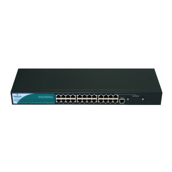
Fiber Slide-in, one Link/Act., one FDX/Col,and one 100 indicator per port. Front Panel The front panel of the Switch consists of 24 (100/10Mbps Auto MDI/ MDI-X) ports. EP-824DX-FS (24) 1. Power The LED lights when the Switch is powered on. If the LED , fails to light, check the AC power con nector to ensure proper i nserti on of t he power cord and that the power switch is tu rned ON. -
Page 6: Rear Panel
Rear Panel The rear panel consists of an AC power socket, a power switch, and a console port. (24) EP-824DX-FS 90~264VAC 47~63Hz Make sure you have installed a 10BASE-T or 100BASE-TX network interface card for connecting a PC to the Switch’s RJ-45 (MDI-X) station ports. If LEDs don’t light after 1. -
Page 7: Switch To Hub
Switch to Hub You can connect any RJ-45 station port on the Switch to the Uplink port of a Hub via straight cable with RJ-45 plugs at both ends. Use Category 3, 4 or 5 cable for standard 10Mbps Ethernet connections, or Category 5 cable for 100Mbps Fast Ethernet connections. -
Page 8: Switch To Switch (Other Devices)
Switch to Switch (Other Devices) The Switch can be connected t o another Switch or o ther devices (Routers, Bridges, etc.) vi a a twisted-pair category 5 UTP/STP straig ht or crossover cable. (24) Straight Cable 1 0 0 / 1 0 M S W I T C H A Crossover Cable FDX/ Col FDX/ Col... -
Page 9: Power Up
A. Technical Specifications General Physical and Environmental RAM Buffer: Total 2.5Mbits per device Standards: IEEE 802.3 10BASE-T Ethernet Filtering Address IEEE 802.3u 100BASE-TX/FX Fast Ethernet Table: ANSI/IEEE Std 802.3 N-way auto-negotiation Packet Filtering/ 148800/14800pps IEEE 802.3 MAC layer frame size: 64-1536 Bytes Forwarding Rate: Wire speed per port (for 100Mbps&10Mbps) IEEE 802.3x flow control for Full-Duplex... -
Page 10: Cable Requirements
B. Cable Requirements 2-Year Warranty The following diagram and table show th e standard RJ-45 receptacle/connector and The manufacturer warrants to the original consumer /purchaser free from defects their pin assignments for the switch-to-n etwork interface card connection , and the straight/crossover cable for the Switch-to-switch/hub/ bridge connection.
Need help?
Do you have a question about the EP-824DX-FS and is the answer not in the manual?
Questions and answers