Advertisement
Quick Links
JY997D20701A
Side
B
Side
Side
A
B
JAPANESE
ENGLISH
FX
-4AD
3U
INSTALLATION MANUAL
Manual Number
JY997D20701
Revision
A
Date
February 2006
This manual describes the part names, dimensions, mounting, and
specifications of the product. Before use, read this manual and manuals of
relevant products fully to acquire proficiency in handling and operating the
product. Make sure to learn all the product information, safety information, and
precautions.
And, store this manual in a safe place so that you can take it out and read it
whenever necessary. Always forward it to the end user.
Registration
The company name and the product name to be described in this manual are
the registered trademarks or trademarks of each company.
Effective February 2006
Specifications are subject to change without notice.
©
2006 Mitsubishi Electric Corporation
Safety Precaution
(Read these precautions before use.)
This manual classify the safety precautions into two categories:
and
.
Indicates that incorrect handling may cause hazardous
conditions, resulting in death or severe injury.
Indicates that incorrect handling may cause hazardous
conditions, resulting in medium or slight personal injury
or physical damage.
Depending on circumstances, procedures indicated by
linked to serious results.
In any case, it is important to follow the directions for usage.
Associated Manuals
Manual name
Manual No.
Description
FX
/ FX
Series
3U
3UC
Describes specifications for
JY997D16701
User's Manual
analog control and
MODEL CODE:
- Analog Control
programming method for FX
09R619
/ FX
Series PLC.
Edition
3UC
FX
3U
/FX
3UC
Series
JY997D16601
Describes PLC programming
Programming Manual
MODEL CODE:
for basic/applied instructions
- B a s i c & A p p l i e d
09R517
and devices.
Instruction Edition
Explains FX
Series PLC
3U
FX
Series
JY997D16501
3U
specification details for I/O,
User's Manual
MODEL CODE:
w i r i n g , i n s t a l l a t i o n , a n d
- Hardware Edition
09R516
maintenance.
Note: FX
Series PLC specification details for I/O, wiring, installation, and
3UC
maintenance can only be found in the Japanese Manual.
How to obtain manuals
For the necessary product manuals or documents, consult with the Mitsubishi
Electric dealer from where you purchase your product.
Certification of UL, cUL standards
The following product has UL and cUL certification.
UL, cUL File Number:E95239
Models:
MELSEC FX
3U
series manufactured
-
FX
4AD
3U
Compliance with EC directive (CE Marking)
This note does not guarantee that an entire mechanical module produced in
accordance with the contents of this note will comply with the following standards.
Compliance to EMC directive and LVD directive for the entire mechanical module
should be checked by the user / manufacturer. For more details please contact the
local Mitsubishi Electric sales site.
Requirement for Compliance with EMC directive
The following products have shown compliance through direct testing (of the identified
standards below) and design analysis (through the creation of a technical construction
file) to the European Directive for Electromagnetic Compatibility (89/336/EEC) when
used as directed by the appropriate documentation.
Type:
Programmable Controller (Open Type Equipment)
Models:
MELSEC FX
series manufactured
3U
from February 1st, 2006
FX
-4AD
3U
Standard
EN61131-2:2003
Compliance with all relevant aspects of the
Programmable controllers
standard.
- Equipment requirements and
• Radiated Emissions
tests
• Mains Terminal Voltage Emissions
• RF immunity
• Fast Transients
• ESD
• Surge
• Conducted
• Power magnetic fields
Caution for EC Directive
The analog special adapters have been found to be compliant to the European
standards in the aforesaid manual and directive. However, for the very best per-
formance from what are in fact delicate measuring and controlled output device
Mitsubishi Electric would like to make the following points;
As analog devices are sensitive by nature, their use should be considered care-
fully. For users of proprietary cables (integral with sensors or actuators), these
users should follow those manufacturers installation requirements.
Mitsubishi Electric recommend that shielded cables should be used. If NO other
EMC protection is provided, then users may experience temporary induced
may also be
errors not exceeding +10%/-10% in very heavy industrial areas.
However, Mitsubishi Electric suggest that if adequate EMC precautions are fol-
lowed with general good EMC practice for the users complete control system,
users should expect normal errors as specified in this manual.
• Sensitive analog cable should not be laid in the same trunking or cable
conduit as high voltage cabling. Where possible users should run analog
cables separately.
• Good cable shielding should be used. Ground the shield of the twisted
shielded cable at one point on the PLC side.
• When reading analog values, EMC induced errors can be smoothed out by
3U
averaging the readings. This can be achieved either through functions on the
special function block for analog input or through a users program in the
FX
3U
Series PLC main unit.
• Please use FX
-4AD while installed in a shielded enclosure. For the details,
3U
refer to the following manual.
→ Refer to the FX
Series User's Manual - Hardware Edition
3U
1. Outline
The FX
3U
-4AD special function block for analog input converts four analog input values
(voltage, current) to digital values and transfers those digital values to the PLC main
unit.
1.1 Incorporated Items
Check if the following product and items are included in the package:
Product
Manual
Special unit/block
No. label
Special Unit/Block No.
This
JY818D33101A
No.0
manual
No.1
No.2
No.3
No.4
No.5
No.6
No.7
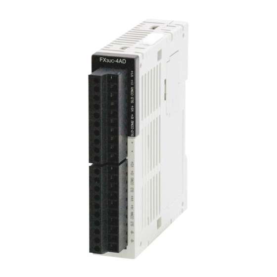
1.2 External Dimensions, Part Names, and Terminal Layout
1.2.1
External Dimensions and Part Names
[1]
[2]
[9]
[8]
9(0.36")
87(3.43")
[1] Direct mounting hole:2 holes of φ4.5 (0.18") (mounting screw: M4 screw)
[2] Extension cable
[3] POWER LED (green):
Remark
Lit while 5V DC power is supplied from PLC.
[4] Terminal block for power supply (24V DC) (M3 terminal screw)
[5] Terminal block for analog input
[6] 24V LED (red):
Lit while 24V DC power is supplied properly to terminals [24+] and [24-].
[7] A/D LED (red):Flashes (at high speed) during A/D conversion.
[8] DIN rail mounting hook
[9] DIN rail mounting groove (35 mm (1.38") wide)
1.2.2 Terminal Layout
24- V+
I+
24+
VI-
FG
CH1
2. Installation
INSTALLATION
PRECAUTIONS
• Use the product in the environment within the general specifications described in
PLC main unit manual (Hardware Edition).
Never use the product in areas with dust, oily smoke, conductive dusts, corrosive
gas (salt air, Cl
, H
S, SO
, or NO
2
2
2
expose it to high temperature, condensation, or wind and rain.
If the product is used in such a place described above, electrical shock, fire,
malfunction, damage, or deterioration may be caused.
• Do not touch the conductive parts of the product directly, thus avoiding failure or
malfunction.
• Install the product securely using the DIN rail or screws.
• Install the product on a flat surface.
If the mounting surface is rough, undue force will be applied to the PC board,
thereby causing nonconformity.
• When drilling screw holes or wiring, cutting chips or wire chips should not enter
ventilation slits.
Such an accident may cause fire, failure or malfunction.
• Be sure to remove the dust proof sheet from the PLC's ventilation port when the
installation work is completed.
Failure to do so could cause fires, equipment failures, and malfunctions.
• Fit the extension cables and communication cables securely to the designated
connectors.
Contact failures may cause malfunctions.
Dust proof sheet × 1
2.1 Arrangements
The product connects on the right side of an PLC main unit or extension units/blocks
(including special function units/blocks).
For connection to FX
3UC
Series PLC or FX
CNV-IF or FX
3UC
-1PS-5V is required.
For further information of installation arrangements, refer to the following manual.
→ Refer to the FX
2.2 Mounting
The product is mounted by the following method.
• Direct mounting
[Without top cover]
• DIN rail mounting
[3]
[4]
2.2.1
Direct Mounting
The product can be mounted with M4 screws by using the direct mounting holes.
Refer to the External Dimensions (section 1.2) for the product's mounting hole
pitch information.
An interval space between each unit of 1 to 2 mm (0.04" to 0.08") is necessary.
For further information of direct installation, also refer to the following manual.
FX
-4AD
3U
2.2.2
DIN Rail Mounting
The product can be mounted on a DIN rail (DIN46227, 35mm width).
4(0.16")
1) Fit the upper edge of the DIN rail mounting
[7]
[6]
[5]
55(2.17")
groove (right fig. A) onto the DIN rail.
2) Press the product against the DIN rail.
MASS(Weight) : Approx. 0.2kg(0.44lbs)
3) Connect the extension cable (right fig. B)
to the main unit, input/output extension
unit/block, and special function unit/block
on the left.
For the details of the extension cable
connection, refer to the following manual.
→ Refer to the FX
V+
I+
V+
I+
V+
I+
VI-
FG
VI-
FG
VI-
CH2
CH3
CH4
Left side of the product
(Extension cable side)
), flammable gas, vibrations or impacts, or
2
2NC
Series PLC extension block, FX
2NC
-
3U
Series User's Manual - Hardware Edition
→ Refer to the FX
3U
Series User's Manual - Hardware Edition
1)
A
2)
Series User's Manual
3U
- Hardware Edition
Advertisement

Related Manuals for Mitsubishi FX3U-4AD


Summary of Contents for Mitsubishi FX3U-4AD
- Page 1 For users of proprietary cables (integral with sensors or actuators), these or physical damage. users should follow those manufacturers installation requirements. Mitsubishi Electric recommend that shielded cables should be used. If NO other 2. Installation EMC protection is provided, then users may experience temporary induced...
- Page 2 Warranty points +15V Mitsubishi will not be held liable for damage caused by factors found not to be 4.2 General Specification 24V DC *1 *1 Change the offset and gain values to change the input characteristics. However, the cause of Mitsubishi; machine damage or lost profits caused by faults in the -15V The items other than the following are equivalent to those of the PLC main unit.
- Page 3 Warranty points +15V Mitsubishi will not be held liable for damage caused by factors found not to be 4.2 General Specification 24V DC *1 *1 Change the offset and gain values to change the input characteristics. However, the cause of Mitsubishi; machine damage or lost profits caused by faults in the -15V The items other than the following are equivalent to those of the PLC main unit.
Need help?
Do you have a question about the FX3U-4AD and is the answer not in the manual?
Questions and answers