Table of Contents
Advertisement
Advertisement
Table of Contents

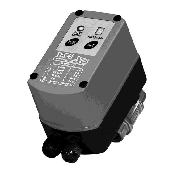
Summary of Contents for Jorc TEC-44
- Page 1 Installation instructions 10-2015...
-
Page 2: Safety & Warning Instructions
SAFETY AND PROPER USAGE To ensure safe and enduring performance of this product, you must comply strictly with the instructions enclosed herein. Non-compliance with instructions or improper handling of the product will void your warranty! Usage of this product in conditions not specified in this manual or in contrary to the instructions hereby provided is considered IMPROPER. -
Page 3: Installation Instructions
4. After double checking that the power supply corresponds with the voltage specified on your TEC-44, you can switch it ON. 5. The TEC-44 will start up in program 4 (see chart 1, page 6). Any changes to the program selection will be stored. Refer to step 6 and 7 for program selections. - Page 5 Housing screw plug (4*) Housing screw (4*) Housing top part (with attached cable) Gasket Motor Housing bottom part Valve indicator Ball valve Washer (2*) Bolt (2*)
- Page 6 INTERVAL TIME (OFF) ROTATION TIME CYCLE (ON) CHART 1 Program Valve closed CHART 2 Program Valve open 4 min 7 seconds rotation (non-stop) 8 min 10 seconds rotation (valve stays open 3 s) 15 min 15 seconds rotation (valve stays open 8 s) 30 min 20 seconds rotation (valve stays open...
-
Page 7: Battery Backup
BATTERY BACKUP The TEC-44 is equipped with a Power Failure Protection Safeguard. The battery back-up is intended to finish a rotation cycle in case of a power failure. The Power Failure Protection Safeguard consists of 4 AA size, 1.5V (penlight) batteries. -
Page 8: Additional Options
ADDITIONAL OPTIONS (1/2) REMOTE SWITCHING The TEC-44 can be controlled by a remote switch. See illustration below how to connect a remote control. Remote switch... - Page 9 ADDITIONAL OPTIONS (2/2) VOLTAGE SWITCH The TEC-44 can be converted to suit 115VAC or 230VAC electrical systems. Use the below mentioned diagrams to configure your drain to the corresponding electrical power supply. 230VAC Place both jumpers on points 2&3. 115VAC Place jumpers on points 1&2...
-
Page 10: Technical Specifications
TECHNICAL SPECIFICATIONS Any size Maximum compressor capacity 0 - 40 bar 0 – 600 psi Pressure range 24VDC, 115VAC and 230VAC 50/60Hz. (depending on model!) Supply voltage options 1 - 60 °C 34 – 140 °F Medium temperature 1 - 55 °C 34 –... - Page 11 SERVICE CHART Date Description Name...
-
Page 12: Dimensions (Mm)
DIMENSIONS (mm)


Need help?
Do you have a question about the TEC-44 and is the answer not in the manual?
Questions and answers
POWER COSUMPTION