Table of Contents
Advertisement
Advertisement
Table of Contents

Related Manuals for Kärcher BD 40/12 C Bp Pack


Summary of Contents for Kärcher BD 40/12 C Bp Pack
- Page 1 BD 40/12 C Bp Pack Service Manual 5.906-510.0 Rev. 00 (12/10)
-
Page 2: Table Of Contents
Contents Preface Safety instructions Safety Devices Hazard levels General notes on safety Technical Features Brush system Water System Suction system Cleaning operations Battery Turbine Brush motor Adjusting the holm tilt Swimmer function 3.10 Operating hours display [h] Setup and function 4.0.1 Operator console Power switch... - Page 3 4.19 Electrical system 4.19.1 Measuring points and fuse 4.19.2 DIP switch Reading faults Check the maintenance-free batteries 1. Measurement - idle voltage 2. Measuring the battery under load 3. Measuring the battery under load Limit value – battery voltage between the individual battery blocks Battery measuring log - maintenance-free battery Replacing a battery due to old age Test the charger...
-
Page 4: Preface
Preface 2.3 General notes on safety First pull out the plug from the mains before carrying Good service work requires extensive and practice- out any tasks on the machine. oriented training as well as well-structured training After completing the maintenace work, check all safe- materials. -
Page 5: Suction System
3.3 Suction system 3.9 Swimmer function The vacuuming does not start automatically when With max. wastewater volume, the floater in the – – the suction bar is lowered. wastewater reservoir closes so that no further suc- tion is possible. To start the vacuuming, the brush head and the –... -
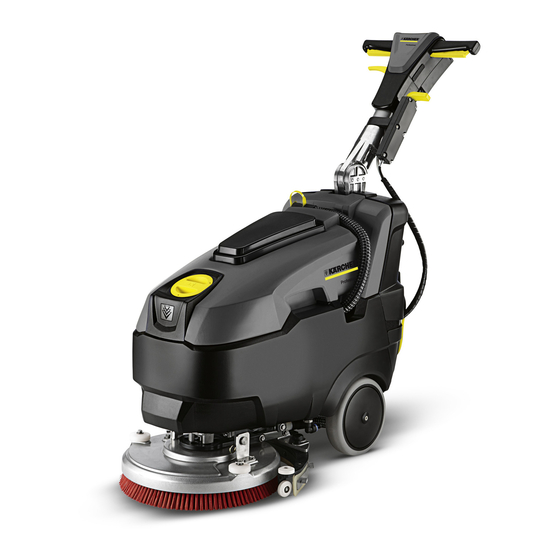
Page 6: Setup And Function
Setup and function 1 Dirt water discharge hose 17 Vacuum bar 2 Push handle 18 Cleaning head 3 Operator console 19 Disc brush 4 Mains cable with mains plug 20 Fresh water reservoir filler neck 5 Vacuum bar lowering lever 21 Fill hose, included 6 Operating lever of brush 22 Cover dirt water reservoir... -
Page 7: Power Switch
4.0.1 Operator console 1 Operating lever of brush 2 Battery status display 3 Switch of suction turbine 4 Switch for brush operations 5 Switch for fresh water / detergent solution 4.1 Power switch 1 Switch 2 Nut Replace the switch 1 Screws ... -
Page 8: Handle
4.2 Handle 1 Nut To preset the bowden cable, screw the nut onto the threaded rod for about 1 cm. 4.3 Suction bar lift 1 Screws 2 Cover Unscrew locking screws. Remove cover. Installation: Please observe the screw length. ... - Page 9 1 Spring Pretension the spring by 1/4 turn. Insert the spring into the groove. Installation: Observe the lever position. 1 Bottom adjustment 2 Top adjustment Installation: The Bowden cable can be adjusted on the top and the bottom. 5.906-510.0 Rev.
-
Page 10: Inclination Settings
4.4 Inclination settings Remove the segment toothed wheel. 1 Screws 2 Strut Unscrew the screws Pull out the holm. 1 Nut 2 Hand lever Unscrew the nut from the threaded rod. Remove the manual lever. 1 Counter-sunk screw 2 Counter-sunk screw 1 Pipe... -
Page 11: Water Filter
4.5 Water filter Installation in reverse order Observe the position of the elongated hole during assembly. Note The stop valve must be closed before opening the water filter. 1 Water filter 2 Locking tap Close the stop valve. ... -
Page 12: Turn Or Replace Vacuum Lips
4.7 Turn or replace vacuum lips 4.9 Setting the vacuum Bar 1 Nut 1 Wing nut 2 Wheel 2 Vacuum lip Loosen the nut. Unscrew the wing nuts. Move the wheel upwards or downwards. Reverse or replace the vacuum lips. ... -
Page 13: Brush Head Drive
4.11 Brush head drive 1 Bolts 2 Safety splint 1 Brush head 2 Safety ring Pull out the securing splint. Pull out the bolt. Reverse the brush head. Remove the safety ring. 1 Ring 2 Hose 1 Flange ... -
Page 14: Removing The Suction Turbine
Note! The water supply for the brush must not be plugged. 1 Screws 4.12 Removing the suction turbine 2 Motor Remove the screws. Remove the motor. 1 Bowden cable Unscrew the bowden cable from the brush head. 1 Cover 2 Carbon brush ... - Page 15 Remove the countersunk screw 1 Cover 2 Dirt water reservoir Note! Replace damaged foam filter. Remove the lid. Remove the dirt water reservoir. 1 Cover 2 Carbon brush (2x) 1 Connection, battery plus terminal 2 Socket plug connection ...
-
Page 16: Replace Solenoid Valve
4.13 Replace solenoid valve 4.14 Removing the wheel 1 Screw 1 Ring 2 Wheel cap 2 Hose 3 Nuts Loosen screws. 4 Solenoid valve Remove the wheel cover. Slide the ring back and pull the hose off at the same time. -
Page 17: Fill In Fresh Water
4.15 Fill in fresh water 4.17 Battery status indicator Lights up when the brush drive switch is switched on, 1 Battery is charged 2 Battery is discharged Battery runtime: The battery runtime on smooth ground and medium discharge current (16 A) is 1 hour. 15 min. 4.18 Battery status values 1 Fill hose 2 Diaphragm... -
Page 18: Battery Status Values
4.19 Electrical system 4.19.1 Measuring points and fuse 1 Hose 2 Screws 3 hood Pull out the hose. Unscrew the fastening screws of the device hood; remove the device hood. 1 Power supply for battery 2 Turbine 3 Brush motor 4 Solenoid valve water 5 Fuse 30 A Measuring values to:... -
Page 19: Dip Switch 1
4.19.2 DIP switch Reading faults DIP switch 1: Fault diagnosis function The built-in battery type can be selected on DIP Display in the battery status field by respective switch 1. blinking of LEDs. ON: Gel battery Fault Visualisation ... -
Page 20: Check The Maintenance-Free Batteries
The battery block with the lowest battery voltage Check the maintenance-free batter- must be replaced if it is outside the tolerance val- ues. See item "Limit value of battery voltage between The battery must be fully charged prior to the inspec- the individual battery blocks". -
Page 21: Replacing A Battery Due To Old Age
Runtime indication: 6.5.1 Measurement - load test How long was Hours / minutes Measure the battery voltage several times while the the customer turbine is turned on. able to work with the appli- Battery Battery Battery Battery ance when the block 1 block 2 block 3... -
Page 22: Test The Charger
6.6.2 Taking out of operation 6.8 Regulated charge ID line IUI charger for maintenance-free batteries If batteries are not to be used for a while, the following AGM / glass mat battery 2.4 / gel 2.35 must be observed when storing them: AGM / glass mat battery 2.25 / gel 2.3 ... -
Page 23: Circuit Diagram
Circuit diagram 7.1 Legend of the electrical components 5.906-510.0 Rev. 00 (12/10) -
Page 24: Specifications
Specifications Current pickup of brush 1.5 A ± 0.2 A head, no load Current pickup of brush 4.0A ± 0.2 A head, loaded Current pickup of suction 10A ± 1A turbine (suction bar up) Max. feed volume of the 20 l/s ± 2 l/s suction turbine (remove suction hose from the suc- tion bar and connect it to the... -
Page 25: Water Function Diagram
Water function diagram 1 Suction turbine 2 Fresh water tank 3 Dirt water reservoir 4 Suction hose 5 Locking tap 6 Vacuum bar 7 Fresh water filter 8 Solenoid valve 9 Dirt water drain hose 10 Disc brush 11 Drain-off tap 12 Fresh water reservoir filler neck 13 Cover dirt water reservoir 5.906-510.0 Rev. -
Page 26: Tools Needed For Installation (Not Supplied)
Tools needed for installation (not supplied) Electronics system 11 Exchange times Charger Power switch Exchange time in minutes per piece Dirt water reservoir Joint of push handle Drain hose Solenoid valve Suction hose Threaded rod for drive lever adjustment Batteries Suction lips Threaded rod Driving lever...
Need help?
Do you have a question about the BD 40/12 C Bp Pack and is the answer not in the manual?
Questions and answers