IAI PSEL Operation Manual
Programmable controller for the robo cylinder
Hide thumbs
Also See for PSEL:
- Operation manual (488 pages) ,
- Operation manual (149 pages) ,
- First step manual (4 pages)

Subscribe to Our Youtube Channel
Related Manuals for IAI PSEL


Summary of Contents for IAI PSEL
- Page 1 PSEL Controller PSEL Controller PSEL Controller Operation Manual Operation Manual Operation Manual Twelfth Eleventh Edition Tenth Edition Edition...
- Page 3 Information contained in this Operation Manual is subject to change without notice for the purpose of product improvement. If you have any question or comment regarding the content of this manual, please contact the IAI sales office near you. Using or copying all or part of this Operation Manual without permission is prohibited.
- Page 4 CE Marking If a compliance with the CE Marking is required, please follow Overseas Standards Compliance Manual (ME0287) that is provided separately.
-
Page 5: Table Of Contents
Part 1 Installation......................9 Chapter 1 Overview ........................... 9 Introduction ............................ 9 Type..............................9 PSEL Controller Functions......................10 System Setup..........................12 Warranty Period and Scope of Warranty ..................13 Chapter 2 Specifications .......................... 14 Controller Specifications....................... 14 Name and Function of Each Part....................15 Name of Each Part...................... - Page 6 Table of Contents Spare consumable parts ......................72 Replacement Procedure for System-Memory Backup Battery (Optional) ........73 Part 2 Programs ....................... 75 Chapter 1 SEL Language Data........................ 75 Values and Symbols Used in SEL Language................75 List of Values and Symbols Used ..................75 I/O Ports ..........................
- Page 7 Table of Contents CIR/ARC Commands ......................... 246 CIR2/ARC2/ARCD/ARCC Commands ..................246 Chapter 5 Palletizing Function (2-axis Specification) ................247 How to Use..........................247 Palletizing Setting........................247 Palletizing Calculation ........................ 252 Palletizing Movement ......................... 253 Program Examples........................254 Chapter 6 Pseudo-Ladder Task ......................256 Basic Frame ..........................
- Page 8 Table of Contents 23. Executing an Operation N times ....................297 24. Constant-pitch Feed........................298 25. Jogging............................299 26. Switching Programs ........................300 27. Aborting a Program ........................301 Part 3 Positioner Mode ................... 302 Chapter 1 Modes and Signal Assignments.................... 302 Feature of Each Mode........................
- Page 9 I/O Devices..........................421 Other Parameters........................422 Manual Operation Types ......................427 Combination Table of PSEL Linear/Rotary Control Parameters ............428 Error Level Control ..........................429 Error List (MAIN application) (In the panel window, the three digits after “E” indicate an error number.) ..............................
-
Page 11: Safety Precautions (Read This Section Before Use)
Part 1 Installation Safety Precautions (Read This Section Before Use) When designing and manufacturing a robot system, ensure safety by following the safety precautions provided below and taking the necessary measures. Regulations and Standards Governing Industrial Robots Safety measures on mechanical devices are generally classified into four categories under the International Industrial Standard ISO/DIS 12100, “Safety of machinery,”... - Page 12 Part 1 Installation Requirements for Industrial Robots under Ordinance on Industrial Safety and Health Cutoff of drive Work area Work condition Measure Article source Signs for starting operation Article 104 Outside During movement automatic Not cut off Installation of railings, Article 150-4 range operation...
- Page 13 Part 1 Installation Applicable Models of IAI’s Industrial Robots Machines meeting the following conditions are not classified as industrial robots according to Notice of Ministry of Labor No. 51 and Notice of Ministry of Labor/Labor Standards Office Director (Ki-Hatsu No.
- Page 14 Part 1 Installation Notes on Safety of Our Products Common items you should note when performing each task on any IAI robot are explained below. Task Note Model This product is not planned or designed for uses requiring high degrees of selection safety.
- Page 15 Installation/ (2) Wiring the cables startup Use IAI’s genuine cables to connect the actuator and controller or connect a teaching tool, etc. Do not damage, forcibly bend, pull, loop round an object or pinch the cables or place heavy articles on top. Current leak or poor electrical continuity may occur, resulting in fire, electric shock or malfunction.
- Page 16 Modification The customer must not modify or disassemble/assemble the product or use maintenance parts not specified in the manual without first consulting IAI. Any damage or loss resulting from the above actions will be excluded from the scope of warranty.
- Page 17 Part 1 Installation Indication of Cautionary Information The operation manual for each model denotes safety precautions under “Danger,” “Warning,” “Caution” and “Note,” as specified below. Level Degree of danger/loss Symbol Failure to observe the instruction will result in an imminent danger Danger Danger leading to death or serious injury.
- Page 18 Part 1 Installation...
-
Page 19: Part 1 Installation
Chapter 1 Overview 1. Introduction Thank you for purchasing the PSEL Controller. Please read this manual carefully, and handle the product with due care and operate it correctly. Keep this manual in a safe place and reference relevant items when needed. -
Page 20: Psel Controller Functions
Teaching mode DS-S-C1 compatible mode The PSEL controller has the “program mode” in which SEL programs are input to operate the actuator(s), and the “positioner mode” in which position numbers are specified from the host PLC to operate the actuator(s). - Page 21 Even after the power is turned off, the internal circuits will continue to carry high voltages for a short period. About actuator duty IAI recommends that our actuators be used at a duty of 50% or less as a guideline in view of the relationship of service life and precision: Accelerati...
-
Page 22: System Setup
Part 1 Installation 4. System Setup Host system Conversion cable Panel unit Teaching pendant Dummy plug Emergency stop switch Enable switch 24-VDC power supply... -
Page 23: Warranty Period And Scope Of Warranty
Defect due to an act of God, accident, fire, etc. The warranty covers only the product as it is delivered. IAI shall not be liable for any loss arising in connection with the delivered product. The user must bring the defective product to our factory to receive a warranty repair. -
Page 24: Chapter 2 Specifications
Contact B input (Internal power-supply type) Position detection method Incremental encoder of A/B two-phase output type System-memory backup battery (Optional) Battery Lithium battery: AB-5 by IAI, 3.6 V/2000 mAh Programming language Super SEL language Number of program steps 2000 steps (total) -
Page 25: Name And Function Of Each Part
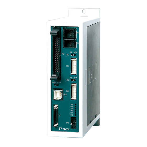
Part 1 Installation 2. Name and Function of Each Part Name of Each Part 2.1.1 Front View [1] Axis 1 motor connector [9] PIO connector [2] Axis 2 motor connector [3] Axis 1 brake-release switch [4] Axis 1 encoder connector [5] Axis 2 brake-release [10] MANU/AUTO switch switch... -
Page 26: Down View
Part 1 Installation 2.1.2 Down View [14] Control power & system I/O connector [15] Motor power connector 2.1.3 Top View [13] System-memory backup battery connector... - Page 27 Part 1 Installation [1] Axis 1 motor connector (M1): This connector is used to connect the motor cable for axis 1. Motor Connector Specifications Item Specification Remarks Applicable AMP Dynamic 0-1376136-1 (AMP) connector D2100, 6 pins Cable-end 0-1318119-3 (AMP) connector Contact: 1318107-1 (AMP) Connector name Maximum...
- Page 28 Part 1 Installation [4] Axis 1 encoder/sensor This connector is used to connect the encoder cable for axis 1. It connector (PG1): connects the encoder cable of the actuator constituting axis 1. Encoder Connector Specifications Item Specification Remarks Applicable connector 2-mm pitch, double- S16B-PHDSS (JST) row connector, 16 pins...
- Page 29 Part 1 Installation [5] Axis 2 brake-release switch This switch is used to forcibly release the electromagnetic brake of (BK2): the actuator constituting axis 2. The specifications are the same as those of the axis 1 brake-release switch in [3]. [6] Axis 2 encoder/sensor This connector is used to connect to the encoder cable for axis 2.
- Page 30 Part 1 Installation I/O Interface List (Program mode) Pin No. Category Port No. Function Cable color External power supply 24 V 1-Brown Program specification (PRG No. 1) 1-Red Program specification (PRG No. 2) 1-Orange Program specification (PRG No. 4) 1-Yellow Program specification (PRG No.
- Page 31 Operation Manual for X-SEL PC Software. When the USB port is used, a dummy plug must be plugged into the teaching connector [12]. Dummy plug model: DP-3 (For PSEL-C) DP-4S (For PSEL-CS)
- Page 32 Part 1 Installation [12] Teaching connector The teaching interface connects IAI’s teaching pendant or a PC (PC (TP): software) to enable operation and setting of your equipment from the teaching pendant/PC. Serial Communication (RS232C) is used for the interface. The signal level conforms to RS232C, and a desired baud rate (maximum 115.2 kbps) can be selected based on the program.
- Page 33 Part 1 Installation Teaching pendant & dedicated communication cable connector Item Specification Remarks Pin No. Signal name Signal ground EMGS Emergency-stop status Power output (Standard IA-T-X/XD power supply (5 V)) Data terminal ready (Shorted to DSR) Not connected Not connected Not connected Power output (ANSI compliant IA-T-XA power supply RSVVCC...
- Page 34 Part 1 Installation [13] System-memory backup This connector is used to install the system-memory backup battery. battery connector: [14] Control power & system This connector is used to input the 24-VDC control power and connect the I/O connector: emergency stop switch and enable switch. The power supply connected to this connector is used for the controller internal power, brake power, and so on, and not used as the motor drive source.
- Page 35 Part 1 Installation [15] Motor power connector: This connector is used to input the 24-VDC motor power. The power supply connected to this connector is used as the dedicated motor drive source. Since the controller has a built-in drive-source cutoff relay, the power supply to the motor will be cut off internally if an emergency stop is actuated or other abnormality occurs.
-
Page 36: Chapter 3 Installation And Wiring
Part 1 Installation Chapter 3 Installation and Wiring 1. External Dimensions (1) 2-axis specification (The same external dimensions also apply to the 1-axis specification.) - Page 37 Part 1 Installation (2) 2-axis specification with battery...
-
Page 38: Installation Environment
Part 1 Installation 2. Installation Environment (1) When installing and wiring the controller, do not block the ventilation holes provided for cooling. (Insufficient ventilation will not only prevent the product from functioning fully, but it may also result in failure.) (2) Prevent foreign matter from entering the controller through the ventilation holes. -
Page 39: Heat Radiation And Installation
Part 1 Installation 3. Heat Radiation and Installation Design the control panel size, controller layout and cooling method so that the surrounding air temperature around the controller will be kept at or below 40°C. Install the controller vertically on a wall, as illustrated below. The controller will be cooled by natural convection. -
Page 40: Noise Control Measures And Grounding
Part 1 Installation 4. Noise Control Measures and Grounding The PSEL controller has no dedicated terminal to connect the FG to ground. Accordingly, provide grounding using the controller mounting screw. [1] Provide dedicated Class D grounding. The grounding wire should have a size of 2.0 to 5.5 mm larger. - Page 41 Part 1 Installation (3) Noise sources and noise elimination There are many noise sources, but solenoid valves, magnet switches and relays are of particular concern when building a system. Noise from these parts can be eliminated using the measures specified below: [1] AC solenoid valve, magnet switch, relay Measure --- Install a surge killer in parallel with the coil.
- Page 42 Part 1 Installation Reference Circuit Diagram Controller +24 V 100 VAC Surge absorber Solenoid valve...
-
Page 43: Supply Voltage
Part 1 Installation 5. Supply Voltage The supply voltage to the controller is 24 VDC 10%. The power-supply current varies depending on the number of axes, as shown below. 1-axis specification 2-axis specification [1] Control power-supply current 1.2 A [2] Rated motor power-input current 1.2 A 2.4 A [3] Maximum motor power-input current... -
Page 44: Wiring
Part 1 Installation 6. Wiring Wiring the Control Power Supply, Emergency Stop Switch and Enable Switch As shown to the left, insert the stripped end of each cable into the control power & system I/O connector, and tighten the screws with a screwdriver. Recommended cable size: 0.75 mm (AWG18) -
Page 45: Wiring The Motor Power Cables
Part 1 Installation Wiring the Motor Power Cables As shown to the left, insert the stripped end of each cable into the motor power connector, and tighten the screws with a screwdriver. Recommended cable size: 2 mm (AWG14) Recommended stripped-wire length: 7 mm As shown to the left, tighten the screws to affix the connector. -
Page 46: Connecting The Actuator
Part 1 Installation Connecting the Actuator 6.3.1 Connecting the Motor Cable (M1/M2) Connect the motor cable from the actuator to the applicable motor connector on the front face of the controller. 6.3.2 Connecting the Encoder Cable (PG1/PG2) Connect the encoder cable from the actuator to the applicable encoder connector on the front face of the controller. -
Page 47: Connecting The Pio Cable (I/O)
Part 1 Installation Connecting the PIO Cable (I/O) Connect the supplied flat cable. Connect the opposite end (open end without connector) of the cable to a desired peripheral (host PLC, etc.). I/O flat cable (supplied): Model number CB-DS-P10020 No connector Flat cable (34 cores) Color Wire... - Page 48 Part 1 Installation 6.4.1 I/O Connection Diagram (1) NPN specification (Program mode) Cable color Pin No. Category Port No. Function 1 – Brown External power supply 24 V 1 – Red Program specification (PRG No. 1) 1 – Orange Program specification (PRG No. 2) 1 –...
- Page 49 Part 1 Installation (2) PNP specification (Program mode) Cable color Pin No. Category Port No. Function 1 – Brown External power supply 24 V 1 – Red Program specification (PRG No. 1) 1 – Orange Program specification (PRG No. 2) 1 –...
- Page 50 Part 1 Installation (3) NPN specification (Standard positioner mode) Positioner mode Cable Pin No.. Port No. Category color CD-S-C1 Model switching 2-axis independent Standard mode Teaching mode compatible mode mode mode 24-V input 1 – Brown Input 10 Axis 1 jog Position input 10 Position input 7 1 –...
- Page 51 Part 1 Installation (4) PNP specification (Standard positioner mode) Positioner mode Cable Pin No.. Port No. Category color CD-S-C1 Model switching 2-axis independent Standard mode Teaching mode compatible mode mode mode 24-V input 1 – Brown Input 10 Axis 1 jog Position input 10 Position input 7 1 –...
-
Page 52: External I/O Specifications
Caution If a non-contact circuit is connected externally, malfunction may result from leakage current. Use a circuit in which leakage current in a switch-off state does not exceed 1 PSEL controller’s input signal ON duration OFF duration At the default settings, the system recognizes the ON/OFF durations of input signals if they are approx. - Page 53 Part 1 Installation (2) Output part External Output Specifications (NPN Specification) Item Specification Load voltage 24 VDC TD62084 (or equivalent) Maximum load current 100 mA per point, 400 mA per 8 ports Note) Leakage current 0.1 mA max. per point Isolation method Photocoupler isolation [1] Miniature relay...
- Page 54 Caution If a non-contact circuit is connected externally, malfunction may result from leakage current. Use a circuit in which leakage current in a switch-off state does not exceed 1 PSEL controller’s input signal ON duration OFF duration At the default settings, the system recognizes the ON/OFF durations of input signals if they are approx.
- Page 55 Part 1 Installation (2) Output part External Output Specifications (PNP Specification) Item Specification Load voltage 24 VDC TD62784 (or equivalent) Maximum load current 100 mA per point, 400 mA per 8 ports Note) Leakage current 0.1 mA max. per point Isolation method Photocoupler isolation [1] Miniature relay...
-
Page 56: Connecting The Teaching Pendant/Pc (Software) (Tp) (Optional)
Part 1 Installation Connecting the Teaching Pendant/PC (Software) (TP) (Optional) The PSEL controller’s teaching connector (TP) is a small, connector. If you are using a teaching pendant or PC software cable, connect the cable to a connector conversion cable, and then connect the conversion cable to the teaching connector on the controller. - Page 57 Part 1 Installation 6.7.1 Explanation of Codes Displayed on the Panel Unit (Optional) (1) Application Display Priority (*1) Description Control power cut off System-down level error Writing data to the flash ROM. Emergency stop is being actuated (except during the update mode). Enable switch (deadman switch/safety gate) OFF (except in the update mode) Cold-start level error Cold-start level error...
- Page 58 Part 1 Installation Display Priority (*1) Description Ready status (auto mode) (Program mode) Ready status (manual mode) (Program mode) Operating in positioner mode; “No.” indicates positioner mode number. Ready status (auto mode) (Positioner mode) Ready status (manual mode) (Positioner mode) (*1) The priority increases as the number decreases.
- Page 59 Part 1 Installation (2) Core Display Priority (*1) Description Control power cut off Cold-start level error Cold-start level error Operation-cancellation level error Operation-cancellation level error Message level error Message level error Application update mode Application update is in progress. Application update has completed. Hardware test mode process Clearing the application flash ROM.
- Page 60 Part 1 Installation 6.7.2 Current Monitor and Variable Monitor By setting other parameter Nos. 49 and 50 appropriately, the optional panel unit can be used to monitor either current levels or variables. (1) Current monitor Currents of up to four axes having continuous axis numbers can be monitored. Parameter settings Other parameter No.
- Page 61 Part 1 Installation (2) Variable monitor The contents of global integer variables can be displayed on the panel window. Positive integers of 1 to 999 can be displayed. Parameter settings Other parameter No. 49 = 2 Other parameter No. 50 = Variable number of the global integer variable to be monitored When data is written to the flash ROM or a software reset (restart) is executed after the parameter values have been input, the panel window will show the content of the global integer variable, instead of “ready status”...
-
Page 62: Installing The System-Memory Backup Battery (Optional)
Part 1 Installation Installing the System-memory Backup Battery (Optional) As shown to the left, install the supplied battery holder on the left side face of the controller. Insert the battery into the holder. Connect the battery connector. Pay attention to the connector orientation. (The connector hook should face the right side.) -
Page 63: Chapter 4 Operation
Part 1 Installation Chapter 4 Operation 1. Startup (1) Connect the motor cable and encoder cable to the controller. (2) Connect the PIO connector to the host PLC using the supplied flat cable. (3) Execute an emergency stop. (4) Connect the PC or teaching pendant. Set the AUTO/MANU switch to the “MANU”... -
Page 64: Power On Sequence
Part 1 Installation Power ON Sequence Although separate inputs are provided for the control power and motor power, they should be supplied from the same power-supply terminal. Turn on the PIO power first. You can turn on the PIO power much earlier than the control power and motor power, as long as it is turned on before the control power/motor power. -
Page 65: How To Use The Simple Absolute Unit (Optional)
How to Connect the Simple Absolute Unit (Optional) Connect the controller, simple absolute unit (optional) and actuator as shown in the figure below. For details on the simple absolute unit, refer to the “Simple Absolute Unit Operation Manual.” PSEL controller Simple absolute unit Dedicated harness... -
Page 66: Setting The Piano Switches For The Simple Absolute Unit (Optional)
Part 1 Installation Setting the Piano Switches for the Simple Absolute Unit (Optional) Set the piano switches for the simple absolute unit (optional). For details, refer to the “Simple Absolute Unit Operation Manual.” * Set the piano switches with the battery disconnected. Connect the battery after changing the piano switch settings. -
Page 67: Setting The Parameters
Perform an absolute reset in the following conditions: [1] The simple absolute unit has been connected to the PSEL controller for use for the first time. [2] The actuator encoder cable has been disconnected and then reconnected from/to the PSEL controller. - Page 68 Part 1 Installation (4) The X-SEL PC software window opens. If an error has been detected, an error message appears. Click the [OK] button to close the error message. If “ABS unit encoder error (2)” has been detected, the following error message appears: (5) You can check the condition of the present error by clicking [Monitor (M)] and then selecting [Error Details (E)].
- Page 69 Part 1 Installation (6) From the menu, click [Controller (C)] and then select [Absolute Reset (A)]. (7) When the [Warning] window appears, click the [OK] button. (8) The [Absolute Reset] window appears. Click here to select the axis which is the target of absolute reset.
- Page 70 Part 1 Installation (9) Click the following process buttons in this order. When each process is completed, the red arrow moves to the next item: Reset Controller Error Turn OFF Servo Initialize Simple ABS Unit Condition Clear Excitation Detection Completed Status Turn ON Servo Home Return Absolute Reset...
- Page 71 Part 1 Installation (10) When the software reset [Confirmation] dialog box appears, click the [Yes (Y)] button to restart the controller. (Note) After an absolute reset, be sure to perform a software reset. (11) As long as no error is present after the restart, the 7-segment LED should show “rdy” if the panel unit is connected.
-
Page 72: How To Start A Program
3. How to Start a Program With the PSEL Controller, the stored programs can be started (run) using four methods. Of these methods, two are mainly used to debug programs or perform trial operations, while the remaining two are used in general applications on site. -
Page 73: Starting A Program By Auto-Start Via Parameter Setting
Part 1 Installation Starting a Program by Auto-Start via Parameter Setting Other parameter No. 7 (Auto program start setting) = 1 (Standard factory setting) This parameter is set using the teaching pendant or PC software. Set the number of the program you wish to start Set an auto-start program number automatically in other parameter No. -
Page 74: Starting Via External Signal Selection
Part 1 Installation Starting via External Signal Selection Select a desired program number externally and then input a start signal. (1) Flow chart Controller External device Power ON Power ON When the READY signal (Output port No. Ready output 301) turns ON, the RDY lamp (green) on the READY signal READY signal controller front panel will illuminate. - Page 75 Part 1 Installation (2) Timing chart [1] Starting a program Duration after the ready output turns ON until input of Ready output external start signal is permitted Program 1 Program 2 T1 = 10 msec min. Duration after the program number is input until input Program of external start signal is permitted number input...
- Page 76 Part 1 Installation [5] When the recovery type after emergency stop or enable operation is set to “Operation continued” Set other parameter No. 10 to “2” and set the input function specification value “7” (operation-pause reset signal) for input port No. *. Set the input function specification value “17“...
-
Page 77: Drive-Source Recovery Request And Operation-Pause Reset Request
Part 1 Installation 4. Drive-Source Recovery Request and Operation-Pause Reset Request (1) Drive-source recovery request [1] Case where a drive-source request is required A drive-source recovery request is required in the following case: Specify a desired input port for receiving the drive-source cutoff reset input signal (dedicated function). -
Page 78: Controller Data Structure
Part 1 Installation 5. Controller Data Structure The controller data consists of parameters as well as position data and application programs used to implement SEL language. PSEL Controller Data Structure Main SEL language Parameters Position Application data programs The user must create position data and application programs. The parameters are predefined, but their settings can be changed in accordance with the user’s system. -
Page 79: How To Save Data
Part 1 Installation How to Save Data The flow to save data in the PSEL controller is illustrated below. When data is transferred from the PC software or teaching pendant to the controller, the data is only written to the main CPU memory as shown in the diagram below and will be erased once the controller is powered down or reset. - Page 80 Part 1 Installation 5.1.2 When the System-Memory Backup Battery (Optional) is Used Change the setting of other parameter No. 20 to 2 (System-memory backup battery installed). Data edited on the PC Data will be retained even after Data will be retained while the power the power is turned off or teaching pendant is on and cleared upon reset...
-
Page 81: Points To Note
Part 1 Installation Points to Note Point to note when transferring data and writing to the flash memory Never turn off the main power while data is being transferred or written to the flash memory. The data will be lost and the controller operation may be disabled. -
Page 82: Chapter 5 Maintenance
Consumable parts Cables System-memory backup battery: (optional): AB-5 by IAI -- Must be replaced after approx. 5 years* *: The actual replacement timing will vary depending on the use condition. For details, refer to “... -
Page 83: Replacement Procedure For System-Memory Backup Battery (Optional)
3. Replacement Procedure for System-Memory Backup Battery (Optional) Backing up the system memory If the optional system-memory backup battery is installed in the PSEL controller and “Other parameter No. 20: Backup battery installation function type” is set to “2” (Installed), the following SRAM data will be... - Page 84 Part 1 Installation Battery Replacement Procedure [1] Remove the battery connector and pull out the battery. [2] Insert a new battery into the holder and plug in the battery connector. The connector hook should face the right side. (8) When the replacement of system-memory backup battery is complete, confirm that the battery is installed securely and then turn on the controller power.
-
Page 85: Part 2 Programs
Part 2 Programs Part 2 Programs Chapter 1 SEL Language Data 1. Values and Symbols Used in SEL Language List of Values and Symbols Used The various functions required in a program are represented by values and symbols. Function Global range Local range Remarks Varies depending on the... -
Page 86: I/O Ports
Integers and real numbers can be used. However, pay due attention to the following limitations: (1) Numeric data The PSEL Controller can handle values of maximum eight digits including a sign and a decimal point. Integer: -9,999,999 to 99,999,999 Real number: Maximum eight digits including a sign and decimal point, regardless of the size of value Example) 999999.9, 0.123456, -0.12345... -
Page 87: Virtual I/O Ports
Part 2 Programs Virtual I/O Ports (1) Virtual input ports Port No. Function 7000 Always OFF 7001 Always ON 7002 Voltage low warning for system-memory backup battery 7003 Abnormal voltage of system-memory backup battery 7004 (For future expansion = Use strictly prohibited) 7005 (For future expansion = Use strictly prohibited) 7006... - Page 88 Part 2 Programs (2) Virtual output ports Port No. Function Latch cancellation output for a latch signal indicating that all-operation-cancellation factor 7300 is present (7011) (latch is cancelled only when operation-cancellation factor is no longer present) (7300 will be turned OFF following an attempt to cancel latch.) 7301 ~ 7380 (For future expansion = Use strictly prohibited)
-
Page 89: Flags
Part 2 Programs Flags Contrary to its common meaning, the term “flag” as used in programming means “memory.” Flags are used to set or reset data. They correspond to “auxiliary relays” in a sequencer. Flags are divided into global flags (Nos. 600 to 899) that can be used in all programs, and local flags (Nos. 900 to 999) that can be used only in each program. -
Page 90: Variables
Part 2 Programs Variables (1) Meaning of variable “Variable” is a technical term used in software programming. Simply put, it means “a box in which a value is put.” Variables can be used in many ways, such as putting in or taking out a value and performing addition or subtraction. - Page 91 Part 2 Programs (2) Types of variables Variables are classified into two types, as follows: [1] Integer variables These variables cannot handle decimal places. [Example] 1234 Integer variable box Variable box 1 1 2 3 4 200 ~ 299 Integer variable number Can be used in all programs “Global integer variables”...
- Page 92 Part 2 Programs [3] Variables with “*” (asterisk) (indirect specification) An “*” (asterisk) is used to specify a variable. In the following example, the content of variable box 1 will be put in variable box 2. If variable box 1 contains “1234,” then “1234” will be put in variable box 2. Command Operand 1 Operand 2...
-
Page 93: Tags
Part 2 Programs Tags The term “tag” means “heading.” Tags are used in the same way you attach labels to the pages in a book you want to reference frequently. A tag is a destination specified in a jump command “GOTO.” Command Operand 1 Tag number (Integer between 1 and 256) -
Page 94: Subroutines
Part 2 Programs Subroutines By taking out the parts of a program that are used repeatedly and registering them as “subroutines,” the same processing can be performed with fewer steps. (A maximum of 15 nests are accommodated.) They are used only in each program. Command Operand 1 EXSR... -
Page 95: Symbols
Part 2 Programs Symbols In the PSEL Controller, values such as variable numbers and flag numbers can be handled as symbols. For the method to edit symbols, refer to “Editing Symbols” in the operation manual for PSEL teaching pendant or “Symbol Edit Window” in the operation manual for PSEL PC software. -
Page 96: Axis Specification
Part 2 Programs 1.10 Axis Specification Axes can be specified based on axis number or axis pattern. (1) Axis numbers and how axes are stated Each of multiple axes is stated as follows: Axis number How axis is stated Axis 1 Axis 2 The axis numbers stated above can also be expressed using symbols. - Page 97 Part 2 Programs (2) Axis pattern Whether or not each axis will be used is indicated by “1” or “0.” (Upper) (Lower) Axis number Axis 2 Axis 1 Used Not used [Example] When axes 1 and 2 are used Axis 2 Axis 1 [Example] When axes 2 is used...
-
Page 98: Position Part
Part 2 Programs SEL language consists of a position part (position data = coordinates, etc.) and a command part (application program). 2. Position Part As position data, coordinates, speeds, accelerations and decelerations are set and stored. Standard *1, 2 Standard 0.3 G 1 ~ 2000/mmsec 2000000.000 mm... -
Page 99: Command Part
Part 2 Programs 3. Command Part The primary feature of SEL language is its very simple command structure. Since the structure is simple, there is no need for a compiler (to translate into computer language) and high-speed operation is possible via an interpreter (the program runs as commands are translated). -
Page 100: Extension Condition
Part 2 Programs Extension Condition Conditions can be combined in a complex manner. (SEL language) AND extension (Ladder diagram) Command Input Extension Condition Output condition Operand Operand condition Command Condition 1 Condition 2 Condition Operand Operand Condition 3 Command Condition OR extension Command Input... -
Page 101: Chapter 2 List Of Sel Language Command Codes
Part 2 Programs Chapter 2 List of SEL Language Command Codes 1. By Function Variables can be specified indirectly in the operand 1, operand 2 and output fields. Symbols can be input in the condition, operand 1, operand 2 and output fields. The input items in ( ) under operand 1 and operand 2 are optional. - Page 102 Part 2 Programs Operation type in the output field CC: Command was executed successfully, ZR: Operation result is zero, PE: Operation is complete, CP: Command part has passed, TU: Time up EQ: Operand 1 = Operand 2, NE: Operand 1 Operand 2, GT: Operand 1 >...
- Page 103 Part 2 Programs Operation type in the output field CC: Command was executed successfully, ZR: Operation result is zero, PE: Operation is complete, CP: Command part has passed, TU: Time up EQ: Operand 1 = Operand 2, NE: Operand 1 Operand 2, GT: Operand 1 >...
- Page 104 Part 2 Programs Operation type in the output field CC: Command was executed successfully, ZR: Operation result is zero, PE: Operation is complete, CP: Command part has passed, TU: Time up EQ: Operand 1 = Operand 2, NE: Operand 1 Operand 2, GT: Operand 1 >...
- Page 105 Part 2 Programs Operation type in the output field CC: Command was executed successfully, ZR: Operation result is zero, PE: Operation is complete, CP: Command part has passed, TU: Time up EQ: Operand 1 = Operand 2, NE: Operand 1 Operand 2, GT: Operand 1 >...
-
Page 106: Alphabetical Order
Part 2 Programs 2. Alphabetical Order Operation type in the output field EQ: Operand 1 = Operand 2, NE: Operand 1 Operand 2, CC: Command was executed successfully, GT: Operand 1 > Operand 2, GE: Operand 1 Operand 2, ZR: Operation result is zero, PE: Operation is complete, CP: Command part has passed, TU: Time up LT: Operand 1 <... - Page 107 Part 2 Programs Operation type in the output field CC: Command was executed successfully, ZR: Operation result is zero, Operation is complete, CP: Command part has passed, TU: Time up EQ: Operand 1 = Operand 2, NE: Operand 1 Operand 2, GT: Operand 1 >...
- Page 108 Part 2 Programs Operation type in the output field CC: Command was executed successfully, ZR: Operation result is zero, Operation is complete, CP: Command part has passed, TU: Time up EQ: Operand 1 = Operand 2, NE: Operand 1 Operand 2, GT: Operand 1 >...
- Page 109 Part 2 Programs Operation type in the output field CC: Command was executed successfully, ZR: Operation result is zero, Operation is complete, CP: Command part has passed, TU: Time up EQ: Operand 1 = Operand 2, NE: Operand 1 Operand 2, GT: Operand 1 >...
- Page 110 Part 2 Programs Operation type in the output field CC: Command was executed successfully, ZR: Operation result is zero, Operation is complete, CP: Command part has passed, TU: Time up EQ: Operand 1 = Operand 2, NE: Operand 1 Operand 2, GT: Operand 1 >...
-
Page 111: Chapter 3 Explanation Of Commands
Part 2 Programs Chapter 3 Explanation of Commands 1. Commands Variable Assignment LET (Assign) Command, declaration Extension condition Input condition Output Command, (LD, A, O, AB, OB) (I/O, flag) (Output, flag) Operand 1 Operand 2 declaration Variable Optional Optional Data number [Function] Assign the value specified in operand 2 to the variable specified in operand 1. - Page 112 Part 2 Programs TRAN (Copy) Command, declaration Extension condition Input condition Output Command, (LD, A, O, AB, OB) (I/O, flag) Operand 1 Operand 2 (Output, flag) declaration Variable Variable Optional Optional TRAN number number [Function] Assign the content of the variable specified in operand 2 to the variable specified in operand 1.
- Page 113 Part 2 Programs CLR (Clear variable) Command, declaration Extension condition Input condition Output Command, (LD, A, O, AB, OB) (I/O, flag) Operand 1 Operand 2 (Output, flag) declaration Variable Variable Optional Optional number number [Function] Clear the variables from the one specified in operand 1 through the other specified in operand 2.
-
Page 114: Arithmetic Operation
Part 2 Programs Arithmetic Operation ADD (Add) Command, declaration Extension condition Input condition Output Command, (LD, A, O, AB, OB) (I/O, flag) (Output, flag) Operand 1 Operand 2 declaration Variable Optional Optional Data number [Function] Add the content of the variable specified in operand 1 and the value specified in operand 2, and assign the result to the variable specified in operand 1. - Page 115 Part 2 Programs MULT (Multiply) Command, declaration Extension condition Input condition Output Command, (LD, A, O, AB, OB) (I/O, flag) Operand 1 Operand 2 (Output, flag) declaration Variable Optional Optional MULT Data number [Function] Multiply the content of the variable specified in operand 1 by the value specified in operand 2, and assign the result to the variable specified in operand 1.
- Page 116 Part 2 Programs MOD (Remainder) Command, declaration Extension condition Input condition Output Command, (LD, A, O, AB, OB) (I/O, flag) Operand 1 Operand 2 (Output, flag) declaration Variable Optional Optional Data number [Function] Assign, to the variable specified in 1, the remainder obtained by dividing the content of the variable specified in operand 1 by the value specified in operand 2.
-
Page 117: Function Operation
Part 2 Programs Function Operation SIN (Sine operation) Command, declaration Extension condition Input condition Output Command, (LD, A, O, AB, OB) (I/O, flag) (Output, flag) Operand 1 Operand 2 declaration Variable Optional Optional Data number [Function] Assign the sine of the data specified in operand 2 to the variable specified in operand 1. The output will turn ON when the operation result becomes 0. - Page 118 Part 2 Programs TAN (Tangent operation) Command, declaration Extension condition Input condition Output Command, (LD, A, O, AB, OB) (I/O, flag) Operand 1 Operand 2 (Output, flag) declaration Variable Optional Optional Data number [Function] Assign the tangent of the data specified in operand 2 to the variable specified in operand 1. The output will turn ON when the operation result becomes 0.
- Page 119 Part 2 Programs SQR (Root operation) Command, declaration Extension condition Input condition Output Command, (LD, A, O, AB, OB) (I/O, flag) Operand 1 Operand 2 (Output, flag) declaration Variable Optional Optional Data number [Function] Assign the root of the data specified in operand 2 to the variable specified in operand 1. The output will turn ON when the operation result becomes 0.
-
Page 120: Logical Operation
Part 2 Programs Logical Operation AND (Logical AND) Command, declaration Extension condition Input condition Output Command, (LD, A, O, AB, OB) (I/O, flag) (Output, flag) Operand 1 Operand 2 declaration Variable Optional Optional Data number [Function] Assign the logical AND operation result of the content of the variable specified in operand 1 and the value specified in operand 2, to the variable specified in operand 1. - Page 121 Part 2 Programs OR (Logical OR) Command, declaration Extension condition Input condition Output Command, (LD, A, O, AB, OB) (I/O, flag) (Output, flag) Operand 1 Operand 2 declaration Variable Optional Optional Data number [Function] Assign the logical OR operation result of the content of the variable specified in operand 1 and the value specified in operand 2, to the variable specified in operand 1.
- Page 122 Part 2 Programs EOR (Logical exclusive-OR) Command, declaration Extension condition Input condition Output Command, (LD, A, O, AB, OB) (I/O, flag) (Output, flag) Operand 1 Operand 2 declaration Variable Optional Optional Data number [Function] Assign the logical exclusive-OR operation result of the content of the variable specified in operand 1 and the value specified in operand 2, to the variable specified in operand 1.
-
Page 123: Comparison Operation
Part 2 Programs Comparison Operation (Compare) Command, declaration Extension condition Input condition Output Command, (LD, A, O, AB, OB) (I/O, flag) (Output, flag) Operand 1 Operand 2 declaration Variable Optional Optional Data number [Function] The output will be turned ON if the comparison result of the content of the variable specified in operand 1 and the value specified in operand 2 satisfies the condition. -
Page 124: Timer
Part 2 Programs Timer TIMW (Timer) Command, declaration Extension condition Input condition Output Command, (LD, A, O, AB, OB) (I/O, flag) (Output, flag) Operand 1 Operand 2 declaration Optional Optional TIMW Time Prohibited [Function] Stop the program and wait for the time specified in operand 1. The setting range is 0.01 to 99, and the unit is second. - Page 125 Part 2 Programs TIMC (Cancel timer) Command, declaration Extension condition Input condition Output Command, (LD, A, O, AB, OB) (I/O, flag) Operand 1 Operand 2 (Output, flag) declaration Program Optional Optional TIMC Prohibited number [Function] Cancel a timer in other program running in parallel. (Note) Timers in TIMW, WTON, WTOF and READ commands can be cancelled.
- Page 126 Part 2 Programs GTTM (Get time) Command, declaration Extension condition Input condition Output Command, (LD, A, O, AB, OB) (I/O, flag) Operand 1 Operand 2 (Output, flag) declaration Variable Optional Optional GTTM Prohibited number [Function] Read system time to the variable specified in operand 1. The time is specified in units of 10 milliseconds.
-
Page 127: I/O, Flag Operation
Part 2 Programs I/O, Flag Operation (Output port, flag operation) Command, declaration Extension condition Input condition Output Command, (LD, A, O, AB, OB) (I/O, flag) (Output, flag) Operand 1 Operand 2 declaration (Output, Optional Optional Output, flag flag) [Function] Reverse the ON/OFF status of the output ports or flags from the one specified in operand 1 through the other specified in operand 2. - Page 128 Part 2 Programs BTPN (Output ON pulse) Command, declaration Extension condition Input condition Output Command, (LD, A, O, AB, OB) (I/O, flag) Operand 1 Operand 2 (Output, flag) declaration Output Timer Optional Optional BTPN port, flag setting [Function] Turn ON the specified output port or flag for the specified time. When this command is executed, the output port or flag specified in operand 1 will be turned ON and then the program will proceed to the next step.
- Page 129 Part 2 Programs BTPF (Output OFF pulse) Command, declaration Extension condition Input condition Output Command, (LD, A, O, AB, OB) (I/O, flag) Operand 1 Operand 2 (Output, flag) declaration Output Timer Optional Optional BTPF port, flag setting [Function] Turn OFF the specified output port or flag for the specified time. When this command is executed, the output port or flag specified in operand 1 will be turned OFF and then the program will proceed to the next step.
- Page 130 Part 2 Programs (Wait for I/O port, flag) Command, declaration Extension condition Input condition Output Command, (LD, A, O, AB, OB) (I/O, flag) Operand 1 Operand 2 (Output, flag) declaration Optional Optional I/O, flag (Time) [Function] Wait for the I/O port or flag specified in operand 1 to turn ON/OFF. The program can be aborted after the specified time by setting the time in operand 2.
- Page 131 Part 2 Programs IN (Read I/O, flag as binary) Command, declaration Extension condition Input condition Output Command, (LD, A, O, AB, OB) (I/O, flag) (Output, flag) Operand 1 Operand 2 declaration Optional Optional I/O, flag I/O, flag [Function] Read the I/O ports or flags from the one specified in operand 1 through the other specified in operand 2, to variable 99 as a binary.
- Page 132 Part 2 Programs INB (Read I/O, flag as BCD) Command, declaration Extension condition Input condition Output Command, (LD, A, O, AB, OB) (I/O, flag) (Output, flag) Operand 1 Operand 2 declaration Optional Optional I/O, flag BCD digits [Function] Read the I/O ports or flags from the one specified in operand 1 for the number of digits specified in operand 2, to variable 99 as a BCD.
- Page 133 Part 2 Programs OUT (Write output, flag as binary) Command, declaration Extension condition Input condition Output Command, (LD, A, O, AB, OB) (I/O, flag) Operand 1 Operand 2 (Output, flag) declaration Optional Optional Output, flag Output, flag [Function] Write the value in variable 99 to the output ports or flags from the one specified in operand 1 through the other specified in operand 2.
- Page 134 Part 2 Programs OUTB (Write output, flag as BCD) Command, declaration Extension condition Input condition Output Command, (LD, A, O, AB, OB) (I/O, flag) (Output, flag) Operand 1 Operand 2 declaration Optional Optional OUTB Output, flag BCD digits [Function] Write the value in variable 99 to the output ports or flags from the one specified in operand 1 for the number of digits specified in operand 2 as a BCD.
- Page 135 Part 2 Programs FMIO (Set IN, INB, OUT, OUTB command format) Command, declaration Extension condition Input condition Output Command, (LD, A, O, AB, OB) (I/O, flag) Operand 1 Operand 2 (Output, flag) declaration Format Optional Optional FMIO Prohibited type [Function] Set the data format for reading or writing I/O ports and flags with an IN, INB, OUT or OUTB command.
- Page 136 Part 2 Programs (4) Operand 1 = 3 Data is read or written after its upper 16 bits and lower 16 bits are reversed every 32 bits and its upper eight bits and lower eight bits are reversed every 16 bits. (I/O, flag number upper) (I/O, flag number lower) 01234567h...
- Page 137 Part 2 Programs [Example 2] Variable 99 = 00001234h (Decimal: 4660, BCD: 1234) OUT(B) command 00001234h Variable 99 4660 (IN/OUT command) IN(B) command 1234 (INB/OUTB command) OUT(B) command IN(B) command (I/O, flag number upper) (I/O, flag number lower) FMIO = 0 00h 00h 12h 34h 0000 0000 0000 0000 0001 0010 0011 0100 FMIO = 1...
-
Page 138: Program Control
Part 2 Programs Program Control GOTO (Jump) Command, declaration Extension condition Input condition Output Command, (LD, A, O, AB, OB) (I/O, flag) (Output, flag) Operand 1 Operand 2 declaration Optional Optional GOTO Prohibited number [Function] Jump to the position of the tag number specified in operand 1. (Note) A GOTO command is valid only within the same program. - Page 139 Part 2 Programs EXSR (Execute subroutine) Command, declaration Extension condition Input condition Output Command, (LD, A, O, AB, OB) (I/O, flag) Operand 1 Operand 2 (Output, flag) declaration Subroutine Optional Optional EXSR Prohibited number [Function] Execute the subroutine specified in operand 1. A maximum of 15 nested subroutine calls are supported.
- Page 140 Part 2 Programs EDSR (End subroutine) Command, declaration Extension condition Input condition Output Command, (LD, A, O, AB, OB) (I/O, flag) Operand 1 Operand 2 (Output, flag) declaration Prohibited Prohibited EDSR Prohibited Prohibited [Function] Declare the end of a subroutine. This command is always required at the end of a subroutine.
-
Page 141: Task Management
Part 2 Programs Task Management EXIT (End program) Command, declaration Extension condition Input condition Output Command, (LD, A, O, AB, OB) (I/O, flag) (Output, flag) Operand 1 Operand 2 declaration Optional Optional EXIT Prohibited Prohibited [Function] End the program. If the last step has been reached without encountering any EXIT command, the program will return to the beginning. - Page 142 Part 2 Programs EXPG (Start other program) Command, declaration Extension condition Input condition Output Command, (LD, A, O, AB, OB) (I/O, flag) Operand 1 Operand 2 (Output, flag) declaration Program (Program Optional Optional EXPG number number) [Function] Start the programs from the one specified in operand 1 through the other specified in operand 2, and run them in parallel.
- Page 143 Part 2 Programs ABPG (Abort other program) Command, declaration Extension condition Input condition Output Command, (LD, A, O, AB, OB) (I/O, flag) Operand 1 Operand 2 (Output, flag) declaration Program (Program Optional Optional ABPG number number) [Function] Forcibly end the programs from the one specified in operand 1 to the other specified in operand 2.
- Page 144 Part 2 Programs SSPG (Pause program) Command, declaration Extension condition Input condition Output Command, (LD, A, O, AB, OB) (I/O, flag) Operand 1 Operand 2 (Output, flag) declaration Program (Program Optional Optional SSPG number number) [Function] Pause the program from the one specified in operand 1 through the other specified in operand 2, at the current step.
- Page 145 Part 2 Programs RSPG (Resume program) Command, declaration Extension condition Input condition Output Command, (LD, A, O, AB, OB) (I/O, flag) Operand 1 Operand 2 (Output, flag) declaration Program (Program Optional Optional RSPG number number) [Function] Resume the programs from the one specified in operand 1 through the other specified in operand 2.
-
Page 146: Position Operation
Part 2 Programs 1.10 Position Operation PGET (Read position data) Command, declaration Extension condition Input condition Output Command, (LD, A, O, AB, OB) (I/O, flag) (Output, flag) Operand 1 Operand 2 declaration Axis Position Optional Optional PGET number number [Function] Read to variable 199 the data of the axis number specified in operand 1 in the position data specified in operand 2. - Page 147 Part 2 Programs PPUT (Write position data) Command, declaration Extension condition Input condition Output Command, (LD, A, O, AB, OB) (I/O, flag) Operand 1 Operand 2 (Output, flag) declaration Axis Position Optional Optional PPUT number number [Function] Write the value in variable 199 to the axis number specified in operand 1 in the position data specified in operand 2.
- Page 148 Part 2 Programs PCLR (Clear position data) Command, declaration Extension condition Input condition Output Command, (LD, A, O, AB, OB) (I/O, flag) Operand 1 Operand 2 (Output, flag) declaration Position Position Optional Optional PCLR number number [Function] Clear the position data from the one specified in operand 1 through the other specified in operand 2.
- Page 149 Part 2 Programs PCPY (Copy position data) Command, declaration Extension condition Input condition Output Command, (LD, A, O, AB, OB) (I/O, flag) Operand 1 Operand 2 (Output, flag) declaration Position Position Optional Optional PCPY number number [Function] Copy the position data specified in operand 2 to the position number specified in operand 1. [Example 1] PCPY Copy the data of position No.
- Page 150 Part 2 Programs PRED (Read current position) Command, declaration Extension condition Input condition Output Command, (LD, A, O, AB, OB) (I/O, flag) Operand 1 Operand 2 (Output, flag) declaration Axis Position Optional Optional PRED pattern number [Function] Read the current position of the axis specified in operand 1 to the position specified in operand 2.
- Page 151 Part 2 Programs PRDQ (Read current axis position (1 axis direct)) Command, declaration Extension condition Input condition Output Command, (LD, A, O, AB, OB) (I/O, flag) (Output, flag) Operand 1 Operand 2 declaration Axis Variable Optional Optional PRDQ number number [Function] Read the current position of the axis number specified in operand 1 to the variable specified in operand 2.
- Page 152 Part 2 Programs PTST (Check position data) Command, declaration Extension condition Input condition Output Command, (LD, A, O, AB, OB) (I/O, flag) (Output, flag) Operand 1 Operand 2 declaration Axis Position Optional Optional PTST pattern number [Function] Check if valid data is contained in the axis pattern specified in operand 1 at the position number specified in operand 2.
- Page 153 Part 2 Programs PVEL (Assign speed data) Command, declaration Extension condition Input condition Output Command, (LD, A, O, AB, OB) (I/O, flag) Operand 1 Operand 2 (Output, flag) declaration Position Optional Optional PVEL Speed number [Function] Write the speed specified in operand 1 to the position number specified in operand 2. (Note) If a negative value is written with a PVEL command, an alarm will generate when that position is specified in a movement operation, etc.
- Page 154 Part 2 Programs PACC (Assign acceleration data) Command, declaration Extension condition Input condition Output Command, (LD, A, O, AB, OB) (I/O, flag) (Output, flag) Operand 1 Operand 2 declaration Position Optional Optional PACC Acceleration number [Function] Write the acceleration specified in operand 1 to the position number specified in operand 2. (Note) Range check is not performed for a PACC command.
- Page 155 Part 2 Programs PDCL (Assign deceleration data) Command, declaration Extension condition Input condition Output Command, (LD, A, O, AB, OB) (I/O, flag) Operand 1 Operand 2 (Output, flag) declaration Position Optional Optional PDCL Deceleration number [Function] Assign the deceleration data specified in operand 1 to the deceleration item in the position data specified in operand 2.
- Page 156 Part 2 Programs PAXS (Read axis pattern) Command, declaration Extension condition Input condition Output Command, (LD, A, O, AB, OB) (I/O, flag) Operand 1 Operand 2 (Output, flag) declaration Variable Position Optional Optional PAXS number number [Function] Store the axis pattern at the position specified in operand 2 to the variable specified in operand 1.
- Page 157 Part 2 Programs PSIZ (Check position data size) Command, declaration Extension condition Input condition Output Command, (LD, A, O, AB, OB) (I/O, flag) (Output, flag) Operand 1 Operand 2 declaration Variable Optional Optional PSIZ Prohibited number [Function] Set an appropriate value in the variable specified in operand 1 in accordance with the parameter setting.
- Page 158 Part 2 Programs GVEL (Get speed data) Command, declaration Extension condition Input condition Output Command, (LD, A, O, AB, OB) (I/O, flag) Operand 1 Operand 2 (Output, flag) declaration Variable Position Optional Optional GVEL number number [Function] Obtain speed data from the speed item in the position data specified in operand 2, and set the value in the variable specified in operand 1.
- Page 159 Part 2 Programs GACC (Get acceleration data) Command, declaration Extension condition Input condition Output Command, (LD, A, O, AB, OB) (I/O, flag) Operand 1 Operand 2 (Output, flag) declaration Variable Position Optional Optional GACC number number [Function] Obtain acceleration data from the acceleration item in the position data specified in operand 2, and set the value in the variable specified in operand 1.
- Page 160 Part 2 Programs GDCL (Get deceleration data) Command, declaration Extension condition Input condition Output Command, (LD, A, O, AB, OB) (I/O, flag) Operand 1 Operand 2 (Output, flag) declaration Variable Position Optional Optional GDCL number number [Function] Obtain deceleration data from the deceleration item in the position data specified in operand 2, and set the value in the variable specified in operand 1.
-
Page 161: Actuator Control Declaration
Part 2 Programs 1.11 Actuator Control Declaration VEL (Set speed) Command, declaration Extension condition Input condition Output Command, (LD, A, O, AB, OB) (I/O, flag) (Output, flag) Operand 1 Operand 2 declaration Optional Optional Speed Prohibited [Function] Set the actuator travel speed in the value specified in operand 1. The unit is mm/s. - Page 162 Part 2 Programs OVRD (Override) Command, declaration Extension condition Input condition Output Command, (LD, A, O, AB, OB) (I/O, flag) Operand 1 Operand 2 (Output, flag) declaration Optional Optional OVRD Speed ratio Prohibited [Function] Reduce the speed in accordance with the ratio specified in operand 1 (speed coefficient setting).
- Page 163 Part 2 Programs ACC (Set acceleration) Command, declaration Extension condition Input condition Output Command, (LD, A, O, AB, OB) (I/O, flag) Operand 1 Operand 2 (Output, flag) declaration Optional Optional Acceleration Prohibited [Function] Set the travel acceleration of the actuator. The maximum acceleration will vary depending on the load and model of the actuator connected.
- Page 164 Part 2 Programs DCL (Set deceleration) Command, declaration Extension condition Input condition Output Command, (LD, A, O, AB, OB) (I/O, flag) Operand 1 Operand 2 (Output, flag) declaration Optional Optional Deceleration Prohibited [Function] Set the travel deceleration of the actuator. The maximum deceleration will vary depending on the load and model of the actuator connected.
- Page 165 Part 2 Programs SCRV (Set sigmoid motion ratio) Command, declaration Extension condition Input condition Output Command, (LD, A, O, AB, OB) (I/O, flag) Operand 1 Operand 2 (Output, flag) declaration Optional Optional SCRV Ratio Prohibited [Function] Set the ratio of sigmoid motion control of the actuator in the value specified in operand 1. The ratio is set as an integer in a range from 0 to 50 (%).
- Page 166 Part 2 Programs OFST (Set offset) Command, declaration Extension condition Input condition Output Command, (LD, A, O, AB, OB) (I/O, flag) Operand 1 Operand 2 (Output, flag) declaration Axis Offset Optional Optional OFST pattern value [Function] Reset the target value by adding the offset value specified in operand 2 to the original target value when performing the actuator movement specified in operand 1.
- Page 167 Part 2 Programs DEG (Set arc angle) Command, declaration Extension condition Input condition Output Command, (LD, A, O, AB, OB) (I/O, flag) Operand 1 Operand 2 (Output, flag) declaration Optional Optional Angle Prohibited [Function] Set a division angle for the interpolation implemented by a CIR (move along circle) or ARC (move along arc) command.
- Page 168 Part 2 Programs BASE (Specify axis base) Command, declaration Extension condition Input condition Output Command, (LD, A, O, AB, OB) (I/O, flag) Operand 1 Operand 2 (Output, flag) declaration Axis Optional Optional BASE Prohibited number [Function] Count the axes sequentially based on the axis number specified in operand 1 being the first axis.
- Page 169 Part 2 Programs GRP (Set group axes) Command, declaration Extension condition Input condition Output Command, (LD, A, O, AB, OB) (I/O, flag) Operand 1 Operand 2 (Output, flag) declaration Axis Optional Optional Prohibited pattern [Function] Allow only the position data of the axis pattern specified in operand 1 to become valid. The program assumes that there are no data for other axes not specified.
- Page 170 Part 2 Programs HOLD (Hold: Declare axis port to pause) Command, declaration Extension condition Input condition Output Command, (LD, A, O, AB, OB) (I/O, flag) Operand 1 Operand 2 (Output, flag) declaration (Input port, (HOLD Optional Optional HOLD global flag) type) [Function] Declare an input port or global flag to pause while a servo command is being executed.
- Page 171 Part 2 Programs CANC (Cancel: Declare axis port to abort) Command, declaration Extension condition Input condition Output Command, (LD, A, O, AB, OB) (I/O, flag) Operand 1 Operand 2 (Output, flag) declaration (Input port, (CANC Optional Optional CANC global flag) type) [Function] Declare an input port or global flag to abort while a servo command is being executed.
- Page 172 Part 2 Programs VLMX (Specify VLMX speed) Command, declaration Extension condition Input condition Output Command, (LD, A, O, AB, OB) (I/O, flag) Operand 1 Operand 2 (Output, flag) declaration Optional Optional VLMX Prohibited Prohibited [Function] Set the actuator travel speed to the VLMX speed (normally maximum speed). Executing a VLMX command will set the value registered in “Axis-specific parameter No.
- Page 173 Part 2 Programs DIS (Set division distance at spline movement) Command, declaration Extension condition Input condition Output Command, (LD, A, O, AB, OB) (I/O, flag) Operand 1 Operand 2 (Output, flag) declaration Optional Optional Distance Prohibited [Function] Set a division distance for the interpolation implemented by a PSPL (move along spline) command.
- Page 174 Part 2 Programs POTP (Set PATH output type) Command, declaration Extension condition Input condition Output Command, (LD, A, O, AB, OB) (I/O, flag) Operand 1 Operand 2 (Output, flag) declaration Optional Optional POTP 0 or 1 Prohibited [Function] Set the output type in the output field to be used when a PATH or PSPL command is executed.
- Page 175 Part 2 Programs PAPR (Set push-motion approach distance, speed) Command, declaration Extension condition Input condition Output Command, (LD, A, O, AB, OB) (I/O, flag) Operand 1 Operand 2 (Output, flag) declaration Optional Optional PAPR Distance Speed [Function] Set the operation to be performed when a PUSH command is executed. Set the distance (push-motion approach distance) over which push-motion approach operation (torque-limiting operation) will be performed in operand 1 (in mm), and set the speed (push-motion approach speed) at which push-motion approach operation...
- Page 176 Part 2 Programs QRTN (Set quick-return mode) Command, declaration Extension condition Input condition Output Command, (LD, A, O, AB, OB) (I/O, flag) Operand 1 Operand 2 (Output, flag) declaration Optional Optional QRTN 0 or 1 Prohibited [Function] Set and cancel the quick-return mode. (1) QRTN [Operand 1] = 0 (Normal mode) Positioning is deemed complete when all command pulses have been output and the current position is inside the positioning band.
-
Page 177: Actuator Control Command
Part 2 Programs 1.12 Actuator Control Command (Turn ON/OFF servo) Command, declaration Extension condition Input condition Output Command, (LD, A, O, AB, OB) (I/O, flag) (Output, flag) Operand 1 Operand 2 declaration Axis Optional Optional Prohibited pattern [Function] Turn ON/OFF the servos of the axes specified by the axis pattern in operand 1. Turn ON the servo. - Page 178 Part 2 Programs HOME (Return to home) Command, declaration Extension condition Input condition Output Command, (LD, A, O, AB, OB) (I/O, flag) Operand 1 Operand 2 (Output, flag) declaration Axis Optional Optional HOME Prohibited pattern [Function] Perform home return of the axes specified by the axis pattern in operand 1. The servo of each home-return axis will turn ON automatically.
- Page 179 Part 2 Programs MOVP (Move PTP by specifying position data) Command, declaration Extension condition Input condition Output Command, (LD, A, O, AB, OB) (I/O, flag) Operand 1 Operand 2 (Output, flag) declaration Position Optional Optional MOVP Prohibited number [Function] Move the actuator to the position corresponding to the position number specified in operand 1, without interpolation (PTP stands for “Point-to-Point”).
- Page 180 Part 2 Programs MOVL (Move by specifying position data) Command, declaration Extension condition Input condition Output Command, (LD, A, O, AB, OB) (I/O, flag) Operand 1 Operand 2 (Output, flag) declaration Position Optional Optional MOVL Prohibited number [Function] Move the actuator to the position corresponding to the position number specified in operand 1, with interpolation.
- Page 181 Part 2 Programs MVPI (Move via incremental PTP) Command, declaration Extension condition Input condition Output Command, (LD, A, O, AB, OB) (I/O, flag) (Output, flag) Operand 1 Operand 2 declaration Position Optional Optional MVPI Prohibited number [Function] Move the actuator, without interpolation, from the current position by the travel distance corresponding to the position number specified in operand 1.
- Page 182 Part 2 Programs MVLI (Move via incremental interpolation) Command, declaration Extension condition Input condition Output Command, (LD, A, O, AB, OB) (I/O, flag) (Output, flag) Operand 1 Operand 2 declaration Position Optional Optional MVLI Prohibited number [Function] Move the actuator, with interpolation, from the current position by the travel distance corresponding to the position number specified in operand 1.
- Page 183 Part 2 Programs MOVD (Move via direct value specification) Command, declaration Extension condition Input condition Output Command, (LD, A, O, AB, OB) (I/O, flag) Operand 1 Operand 2 (Output, flag) declaration Target Optional Optional MOVD (Axis pattern) position [Function] Move the axis specified by the axis pattern in operand 2, to the target position corresponding to the value specified in operand 1.
- Page 184 Part 2 Programs MVDI (Move relatively via direct value specification) Command, declaration Extension condition Input condition Output Command, (LD, A, O, AB, OB) (I/O, flag) (Output, flag) Operand 1 Operand 2 declaration Travel Optional Optional MVDI (Axis pattern) distance [Function] Move the axis specified by the axis pattern in operand 2 from its current position by the travel distance corresponding to the value specified in operand 1.
- Page 185 Part 2 Programs PATH (Move along path) Command, declaration Extension condition Input condition Output Command, (LD, A, O, AB, OB) (I/O, flag) Operand 1 Operand 2 (Output, flag) declaration Start Optional Optional PATH position position number number [Function] Move continuously from the position specified in operand 1 to the position specified in operand 2.
- Page 186 Part 2 Programs (Jog) Command, declaration Extension condition Input condition Output Command, (LD, A, O, AB, OB) (I/O, flag) Operand 1 Operand 2 (Output, flag) declaration Input, Axis Optional Optional output, flag pattern number [Function] The axes in the axis pattern specified in operand 1 will move forward or backward while the input or output port or flag specified in operand 2 is ON or OFF.
- Page 187 Part 2 Programs STOP (Stop movement) Command, declaration Extension condition Input condition Output Command, (LD, A, O, AB, OB) (I/O, flag) (Output, flag) Operand 1 Operand 2 declaration Axis Optional Optional STOP Prohibited pattern [Function] Decelerate and stop the axes specified by the axis pattern in operand 1. (Note 1) A STOP command can be used with all active servo commands other than a SVOF command.
- Page 188 Part 2 Programs PSPL (Move along spline) Command, declaration Extension condition Input condition Output Command, (LD, A, O, AB, OB) (I/O, flag) Operand 1 Operand 2 (Output, flag) declaration Start Optional Optional PSPL position position number number [Function] Continuously move from the specified start position to end position via interpolation along a spline-interpolation curve.
- Page 189 Part 2 Programs PUSH (Move by push motion) Command, declaration Extension condition Input condition Output Command, (LD, A, O, AB, OB) (I/O, flag) Operand 1 Operand 2 (Output, flag) declaration Target Optional Optional PUSH position Prohibited number [Function] Perform push-motion operation until the target position specified in operand 1 is reached. The axes move in a normal mode from the position origin to the push-motion approach start position as determined by a PAPR command, after which push-motion approach operation (toque-limiting operation) will be performed.
- Page 190 Part 2 Programs [Example] PAPR MOVP PUSH Set the push-motion approach distance to 100 mm and push-motion approach speed to 20 mm/sec. Move from the current position to position No. 2. Perform push-motion movement from position Nos. 2 to 10. The diagram below describes a push-motion movement based on the position data shown in the table below: Position data display in PC software...
- Page 191 Part 2 Programs PTRQ (Change push torque limit parameter) Command, declaration Extension condition Input condition Output Command, (LD, A, O, AB, OB) (I/O, flag) Operand 1 Operand 2 (Output, flag) declaration Axis Optional Optional PTRQ Ratio pattern [Function] Change the push torque limit parameter of the axis pattern specified in operand 1 to the value in operand 2.
- Page 192 Part 2 Programs CIR2 (Move along circle 2 (arc interpolation)) Command, declaration Extension condition Input condition Output Command, (LD, A, O, AB, OB) (I/O, flag) Operand 1 Operand 2 (Output, flag) declaration Passing Passing Optional Optional CIR2 position 1 position 2 number number [Function] Move along a circle originating from the current position and passing positions 1 and 2, via...
- Page 193 Part 2 Programs ARC2 (Move along circle 2 (arc interpolation)) Command, declaration Extension condition Input condition Output Command, (LD, A, O, AB, OB) (I/O, flag) Operand 1 Operand 2 (Output, flag) declaration Passing Optional Optional ARC2 position position number number [Function] Move along an arc originating from the current position, passing the specified position and terminating at the end position, via arc interpolation.
- Page 194 Part 2 Programs CHVL (Change speed) Command, declaration Extension condition Input condition Output Command, (LD, A, O, AB, OB) (I/O, flag) (Output, flag) Operand 1 Operand 2 declaration Optional Optional CHVL Axis pattern Speed [Function] Change the speed of the axes operating in other task. When a CHVL command is executed, the speed of the axes specified in operand 1 will change to the value specified in operand 2.
- Page 195 Part 2 Programs ARCD (Move along arc via specification of end position and center angle (arc interpolation)) Command, declaration Extension condition Input condition Output Command, (LD, A, O, AB, OB) (I/O, flag) Operand 1 Operand 2 (Output, flag) declaration Center Optional Optional ARCD...
- Page 196 Part 2 Programs ARCC (Move along arc via specification of center position and center angle (arc interpolation)) Command, declaration Extension condition Input condition Output Command, (LD, A, O, AB, OB) (I/O, flag) Operand 1 Operand 2 (Output, flag) declaration Center Center Optional Optional...
- Page 197 Part 2 Programs PBND (Set positioning band) Command, declaration Extension condition Input condition Output Command, (LD, A, O, AB, OB) (I/O, flag) Operand 1 Operand 2 (Output, flag) declaration Axis Optional Optional PBND Distance pattern [Function] Set the position complete width for the axes in the axis pattern specified in operand 1. The distance in operand 2 is set in mm.
- Page 198 Part 2 Programs CIR (Move along circle) Command, declaration Extension condition Input condition Output Command, (LD, A, O, AB, OB) (I/O, flag) Operand 1 Operand 2 (Output, flag) declaration Passing Passing Optional Optional position 1 position 2 number number [Function] Move along a circle originating from the current position and passing the positions specified in operands 1 and 2.
- Page 199 Part 2 Programs ARC (Move along arc) Command, declaration Extension condition Input condition Output Command, (LD, A, O, AB, OB) (I/O, flag) Operand 1 Operand 2 (Output, flag) declaration Passing Optional Optional position position number number [Function] Move along an arc from the current position to the position specified in operand 2, by passing the position specified in operand 1.
-
Page 200: Structural If
Part 2 Programs 1.13 Structural IF (Structural IF) Command, declaration Extension condition Input condition Output Command, (LD, A, O, AB, OB) (I/O, flag) (Output, flag) Operand 1 Operand 2 declaration Variable Optional Optional Data number [Function] Compare the content of the variable specified in operand 1 with the value specified in operand 2, and proceed to the next step if the condition is satisfied. - Page 201 Part 2 Programs (Compare strings) Command, declaration Extension condition Input condition Output Command, (LD, A, O, AB, OB) (I/O, flag) Operand 1 Operand 2 (Output, flag) declaration Column Column number, Optional Optional number character literal [Function] Compare the character strings in the columns specified in operands 1 and 2, and proceed to the next step if the condition is satisfied.
- Page 202 Part 2 Programs ELSE (Else) Command, declaration Extension condition Input condition Output Command, (LD, A, O, AB, OB) (I/O, flag) Operand 1 Operand 2 (Output, flag) declaration Prohibited Prohibited ELSE Prohibited Prohibited [Function] An ELSE command is used arbitrarily in conjunction with an IF or IS command to declare the command part to be executed when the condition is not satisfied.
-
Page 203: Structural Do
Part 2 Programs 1.14 Structural DO (DO WHILE) Command, declaration Extension condition Input condition Output Command, (LD, A, O, AB, OB) (I/O, flag) (Output, flag) Operand 1 Operand 2 declaration Variable Optional Optional Data number [Function] Compare the content of the variable specified in operand 1 with the value specified in operand 2, and execute the subsequent commands up to EDDO while the condition is satisfied. - Page 204 Part 2 Programs ITER (Repeat) Command, declaration Extension condition Input condition Output Command, (LD, A, O, AB, OB) (I/O, flag) Operand 1 Operand 2 (Output, flag) declaration Optional Optional ITER Prohibited Prohibited [Function] Forcibly switch the control to EDDO while in a DO loop.
-
Page 205: Multi-Branching
Part 2 Programs 1.15 Multi-Branching SLCT (Start selected group) Command, declaration Extension condition Input condition Output Command, (LD, A, O, AB, OB) (I/O, flag) (Output, flag) Operand 1 Operand 2 declaration Optional Optional SLCT Prohibited Prohibited [Function] Branch to the step next to any WH or WS command that exists before an EDSL command and whose condition is satisfied, or to the step next to an OTHE command if none... - Page 206 Part 2 Programs (Select if true; variable) Command, declaration Extension condition Input condition Output Command, (LD, A, O, AB, OB) (I/O, flag) Operand 1 Operand 2 (Output, flag) declaration Variable Prohibited Prohibited Data number [Function] This command is used between SLCT and EDSL commands to execute the subsequent commands up to the next W command or an OTHE or EDSL command when the comparison result of the content of the variable specified in operand 1 with the value specified...
- Page 207 Part 2 Programs (Select if true; character) Command, declaration Extension condition Input condition Output Command, (LD, A, O, AB, OB) (I/O, flag) Operand 1 Operand 2 (Output, flag) declaration Column Column number, Prohibited Prohibited number character literal [Function] This command is used between SLCT and EDSL commands to execute the subsequent commands up to the next W command or an OTHE or EDSL command when the comparison result of the character strings in the columns specified in operands 1 and 2...
- Page 208 Part 2 Programs OTHE (Select other) Command, declaration Extension condition Input condition Output Command, (LD, A, O, AB, OB) (I/O, flag) Operand 1 Operand 2 (Output, flag) declaration Prohibited Prohibited OTHE Prohibited Prohibited [Function] This command is used between SLCT and EDSL commands to declare the command to be executed when none of the conditions are satisfied.
-
Page 209: System Information Acquisition
Part 2 Programs 1.16 System Information Acquisition AXST (Get axis status) Command, declaration Extension condition Input condition Output Command, (LD, A, O, AB, OB) (I/O, flag) (Output, flag) Operand 1 Operand 2 declaration Variable Axis Optional Optional AXST number number [Function] Store in the variable specified in operand 1 the status (axis error number) of the axis specified in operand 2. - Page 210 Part 2 Programs PGST (Get program status) Command, declaration Extension condition Input condition Output Command, (LD, A, O, AB, OB) (I/O, flag) Operand 1 Operand 2 (Output, flag) declaration Variable Program Optional Optional PGST number number [Function] Store in the variable specified in operand 1 the status (program error number) of the program specified in operand 2.
- Page 211 Part 2 Programs SYST (Get system status) Command, declaration Extension condition Input condition Output Command, (LD, A, O, AB, OB) (I/O, flag) Operand 1 Operand 2 (Output, flag) declaration Variable Optional Optional SYST Prohibited number [Function] Store the system status (top-priority system error number) in the variable specified in operand 1.
-
Page 212: Zone
Part 2 Programs 1.17 Zone WZNA (Wait for zone ON, with AND) Command, declaration Extension condition Input condition Output Command, (LD, A, O, AB, OB) (I/O, flag) (Output, flag) Operand 1 Operand 2 declaration Zone Axis Optional Optional WZNA number pattern [Function] Wait for the zone status of all axes (AND) specified by the axis pattern in operand 2 to... - Page 213 Part 2 Programs WZNO (Wait for zone ON, with OR) Command, declaration Extension condition Input condition Output Command, (LD, A, O, AB, OB) (I/O, flag) Operand 1 Operand 2 (Output, flag) declaration Zone Axis Optional Optional WZNO number pattern [Function] Wait for the zone status of any of the axes (OR) specified by the axis pattern in operand 2 to become ON (inside zone) with respect to the zone specified in operand 1.
- Page 214 Part 2 Programs WZFA (Wait for zone OFF, with AND) Command, declaration Extension condition Input condition Output Command, (LD, A, O, AB, OB) (I/O, flag) Operand 1 Operand 2 (Output, flag) declaration Zone Axis Optional Optional WZFA number pattern [Function] Wait for the zone status of all axes (AND) specified by the axis pattern in operand 2 to become OFF (outside zone) with respect to the zone specified in operand 1.
- Page 215 Part 2 Programs WZFO (Wait for zone OFF, with OR) Command, declaration Extension condition Input condition Output Command, (LD, A, O, AB, OB) (I/O, flag) Operand 1 Operand 2 (Output, flag) declaration Zone Axis Optional Optional WZFO number pattern [Function] Wait for the zone status of any of the axes (OR) specified by the axis pattern in operand 2 to become OFF (outside zone) with respect to the zone specified in operand 1.
-
Page 216: Communication
Part 2 Programs 1.18 Communication OPEN (Open channel) Command, declaration Extension condition Input condition Output Command, (LD, A, O, AB, OB) (I/O, flag) (Output, flag) Operand 1 Operand 2 declaration Channel Optional Optional OPEN Prohibited number [Function] Open the channel specified in operand 1. The specified channel will be enabled to send/receive hereafter. - Page 217 Part 2 Programs READ (Read) Command, declaration Extension condition Input condition Output Command, (LD, A, O, AB, OB) (I/O, flag) Operand 1 Operand 2 (Output, flag) declaration Channel Column Optional Optional READ number number [Function] Read a character string from the channel specified in operand 1 to the column specified in operand 2.
- Page 218 Part 2 Programs (Note) A READ command must be executed before the other side sends the end character. SCHA OPEN READ Other side CLOS Return code of the READ command The return code is stored in a local variable. The variable number can be set by “Other parameter No.
- Page 219 [Function] Set the timeout to be applied to a READ/WRIT command. With the PSEL controller, a write timer setting cannot be specified. The timer setting specified in operand 1 will set the maximum time the program will wait for the character string read to end when a READ command is executed.
- Page 220 Part 2 Programs Read completes successfully within 30 seconds Variable No. 1 = 0 Timeout occurs Variable No. 1 = 1 * The return code of READ command may not be limited to 0 or 1. The variable to store the return code can be set in “Other parameter No. 24.” Refer to the explanation of READ command for details.
- Page 221 PSEL. The return code is stored in a local variable. The variable number can be set by “Other parameter No. 24.”...
- Page 222 Part 2 Programs SCHA (Set end character) Command, declaration Extension condition Input condition Output Command, (LD, A, O, AB, OB) (I/O, flag) (Output, flag) Operand 1 Operand 2 declaration Character Optional Optional SCHA Prohibited code [Function] Set the end character to be used by a READ or WRIT command. Any character from 0 to 255 (character code used in BASIC, etc.) can be specified.
-
Page 223: String Operation
Part 2 Programs 1.19 String Operation SCPY (Copy character string) Command, declaration Extension condition Input condition Output Command, (LD, A, O, AB, OB) (I/O, flag) (Output, flag) Operand 1 Operand 2 declaration Column Column Optional Optional SCPY number, number character literal [Function] Copy the character string in the column specified in operand 2 to the column specified in operand 1. - Page 224 Part 2 Programs SCMP (Compare character strings) Command, declaration Extension condition Input condition Output Command, (LD, A, O, AB, OB) (I/O, flag) (Output, flag) Operand 1 Operand 2 declaration Column Column Optional Optional SCMP number, number character literal [Function] Compare the column specified in operand 1 with the column specified in operand 2. Comparison will be performed for the length set by a SLEN command.
- Page 225 Part 2 Programs SGET (Get character) Command, declaration Extension condition Input condition Output Command, (LD, A, O, AB, OB) (I/O, flag) Operand 1 Operand 2 (Output, flag) declaration Column Variable Optional Optional SGET number, number character literal [Function] Assign one character from the column specified in operand 2 to the variable specified in operand 1.
- Page 226 Part 2 Programs SPUT (Set character) Command, declaration Extension condition Input condition Output Command, (LD, A, O, AB, OB) (I/O, flag) Operand 1 Operand 2 (Output, flag) declaration Column Optional Optional SPUT Data number [Function] Set the data specified in operand 2 in the column specified in operand 1. [Example] SPUT Set 10 (LF) in column 5.
- Page 227 Part 2 Programs STR (Convert character string; decimal) Command, declaration Extension condition Input condition Output Command, (LD, A, O, AB, OB) (I/O, flag) (Output, flag) Operand 1 Operand 2 declaration Column Optional Optional Data number [Function] Copy to the column specified in operand 1 a decimal character string converted from the data specified in operand 2.
- Page 228 Part 2 Programs STRH (Convert character string; hexadecimal) Command, declaration Extension condition Input condition Output Command, (LD, A, O, AB, OB) (I/O, flag) Operand 1 Operand 2 (Output, flag) declaration Column Optional Optional STRH Data number [Function] Copy to the column specified in operand 1 a hexadecimal character string converted from the data specified in operand 2.
- Page 229 Part 2 Programs VAL (Convert character string data; decimal) Command, declaration Extension condition Input condition Output Command, (LD, A, O, AB, OB) (I/O, flag) Operand 1 Operand 2 (Output, flag) declaration Column Variable Optional Optional number, number character literal [Function] Convert the decimal data in the column specified in operand 2 to a binary and assign the result to the variable specified in operand 1.
- Page 230 Part 2 Programs VALH (Convert character string data; hexadecimal) Command, declaration Extension condition Input condition Output Command, (LD, A, O, AB, OB) (I/O, flag) Operand 1 Operand 2 (Output, flag) declaration Column Variable Optional Optional VALH number, number character literal [Function] Convert the hexadecimal data in the column specified in operand 2 to a binary and assign the result to the variable specified in operand 1.
- Page 231 Part 2 Programs SLEN (Set length) Command, declaration Extension condition Input condition Output Command, (LD, A, O, AB, OB) (I/O, flag) (Output, flag) Operand 1 Operand 2 declaration Character Optional Optional SLEN string Prohibited length [Function] Set the length to be processed by a string command. This must always be set before using the following commands: SCMP Decimal part is invalid.
-
Page 232: Arch-Motion-Related
Part 2 Programs 1.20 Arch-Motion-Related ARCH (Arch motion) Command, declaration Extension condition Input condition Output Command, (LD, A, O, AB, OB) (I/O, flag) (Output, flag) Operand 1 Operand 2 declaration Position Position Optional Optional ARCH number number Perform arch motion from the current point and move to the specified points. Move to the points specified in operand 1, via arch motion. - Page 233 Part 2 Programs The arch-motion Z-axis will come down after a rise-process command value is output. Therefore, one of the following operations will be performed depending on how the arch-trigger point and Z point are set. If the resulting operation is undesirable, change the arch trigger and/or Z point to improve the efficiency of movement.
- Page 234 Part 2 Programs ACHZ (Declare arch-motion Z-axis) Command, declaration Extension condition Input condition Output Command, (LD, A, O, AB, OB) (I/O, flag) (Output, flag) Operand 1 Operand 2 declaration Axis Optional Optional ACHZ Prohibited number Specify the axis number representing the arch-motion Z direction. The axis number specified in operand 1 will be set as the axis number representing the arch-motion Z direction.
- Page 235 Part 2 Programs ATRG (Set arch triggers) Command, declaration Extension condition Input condition Output Command, (LD, A, O, AB, OB) (I/O, flag) Operand 1 Operand 2 (Output, flag) declaration Position Position Optional Optional ATRG number number Set the arch triggers used for arch motion. (This setting becomes valid when an ARCH command is executed.) Set the arch-motion Z-axis position data in the point data specified in operand 1 as the start-point arch trigger, and set the arch-motion Z-axis position data in the point data specified in operand 2 as the...
- Page 236 Part 2 Programs OFAZ (Set arch-motion Z-axis offset) Command, declaration Extension condition Input condition Output Command, (LD, A, O, AB, OB) (I/O, flag) Operand 1 Operand 2 (Output, flag) declaration Offset Optional Optional OFAZ Prohibited value Set the offset in the arch-motion Z-axis direction. The value specified in operand 1 will be set as the offset in the arch-motion Z-axis direction.
-
Page 237: Palletizing-Related
Part 2 Programs 1.21 Palletizing-Related BGPA (Declare start of palletizing setting) Command, declaration Extension condition Input condition Output Command, (LD, A, O, AB, OB) (I/O, flag) (Output, flag) Operand 1 Operand 2 declaration Palletizing Optional Optional BGPA Prohibited number Declare the start of a palletizing setting. Once this command is executed, palletizing setting for the palletizing number specified in operand 1 will be enabled. - Page 238 Part 2 Programs PAPI (Set palletizing counts) Command, declaration Extension condition Input condition Output Command, (LD, A, O, AB, OB) (I/O, flag) Operand 1 Operand 2 (Output, flag) declaration Optional Optional PAPI Count Count Set counts in the palletizing-axis directions. The count specified in operand 1 will apply to the preferential-axis (PX-axis) direction, while the count specified in operand 2 will apply to the PY-axis direction.
- Page 239 Part 2 Programs PASE (Declare palletizing axes) Command, declaration Extension condition Input condition Output Command, (LD, A, O, AB, OB) (I/O, flag) Operand 1 Operand 2 (Output, flag) declaration Axis Axis Optional Optional PASE number number Set the two axes to be used in palletizing (PX and PY-axes). The axis specified in operand 1 will be set as the preferential axis (PX-axis).
- Page 240 Part 2 Programs PAST (Set palletizing reference point) Command, declaration Extension condition Input condition Output Command, (LD, A, O, AB, OB) (I/O, flag) Operand 1 Operand 2 (Output, flag) declaration (Position Optional Optional PAST Prohibited number) Set the reference point used in palletizing. If a value is set in operand 1, that position number specified in operand 1 will be used to store the reference point data.
- Page 241 Part 2 Programs PAPS (Set palletizing points) For 3-point teaching Command, declaration Extension condition Input condition Output Command, (LD, A, O, AB, OB) (I/O, flag) Operand 1 Operand 2 (Output, flag) declaration (Palletizing Position Optional Optional PAPS position number setting type) Set palletizing positions in 3-point teaching.
- Page 242 Part 2 Programs If the valid axis pattern does not match the point data for 3-point teaching or 4-point teaching, an error “CB0, Mismatched valid axes for palletizing 3-point teaching data” will generate. If a PAPS command is executed after specifying the applicable axes using a GRP command, only the point data corresponding to the specified axes, among all axes whose point data is valid, will be used as palletizing point data.
- Page 243 Part 2 Programs PSLI (Set zigzag) Command, declaration Extension condition Input condition Output Command, (LD, A, O, AB, OB) (I/O, flag) Operand 1 Operand 2 (Output, flag) declaration Offset Optional Optional PSLI (Count) amount Set a zigzag palletizing. The value specified in operand 1 will be set as the offset amount for even-numbered rows. The count specified in operand 2 will be set as the count for even-numbered rows.
-
Page 244: Palletizing Calculation Command
Part 2 Programs 1.22 Palletizing Calculation Command PTNG (Get palletizing position number) Command, declaration Extension condition Input condition Output Command, (LD, A, O, AB, OB) (I/O, flag) (Output, flag) Operand 1 Operand 2 declaration Palletizing Variable Optional Optional PTNG number number Assign the palletizing position number for the palletizing number specified in operand 1 to the variable specified in operand 2. - Page 245 Part 2 Programs PDEC (Decrement palletizing position number by 1) Command, declaration Extension condition Input condition Output Command, (LD, A, O, AB, OB) (I/O, flag) Operand 1 Operand 2 (Output, flag) declaration Palletizing Optional Optional PDEC Prohibited number Decrement by 1 the palletizing position number for the palletizing number specified in operand 1. If the decremented value is considered normal as a palletizing position calculated under the current palletizing setting, the value will be updated.
- Page 246 Part 2 Programs PARG (Get palletizing angle) Command, declaration Extension condition Input condition Output Command, (LD, A, O, AB, OB) (I/O, flag) Operand 1 Operand 2 (Output, flag) declaration Palletizing Axis Optional Optional PARG number number Obtain the palletizing angle. Calculate the palletizing angle (degrees) from the physical axis specified in operand 2 for the palletizing number specified in operand 1, and store the result in variable 199.
-
Page 247: Palletizing Movement Command
Part 2 Programs 1.23 Palletizing Movement Command PMVP (Move to palletizing points via PTP) Command, declaration Extension condition Input condition Output Command, (LD, A, O, AB, OB) (I/O, flag) (Output, flag) Operand 1 Operand 2 declaration Palletizing Optional Optional PMVP Prohibited number Move to the calculated palletizing points via PTP. - Page 248 Part 2 Programs PMVL (Move to palletizing points via interpolation) Command, declaration Extension condition Input condition Output Command, (LD, A, O, AB, OB) (I/O, flag) Operand 1 Operand 2 (Output, flag) declaration Palletizing Optional Optional PMVL Prohibited number Move to the calculated palletizing points via interpolation. The axes will move to the palletizing points specified in operand 1, via interpolation.
-
Page 249: Building Of Pseudo-Ladder Task
Part 2 Programs 1.24 Building of Pseudo-Ladder Task CHPR (Change task level) Command, declaration Extension condition Input condition Output Command, (LD, A, O, AB, OB) (I/O, flag) (Output, flag) Operand 1 Operand 2 declaration Optional Optional CHPR 0 or 1 Prohibited [Function] Specify “1”... - Page 250 Part 2 Programs TSLP (Task sleep) Command, declaration Extension condition Input condition Output Command, (LD, A, O, AB, OB) (I/O, flag) Operand 1 Operand 2 (Output, flag) declaration Prohibited Prohibited TSLP Time Prohibited [Function] Set the time during which the applicable task will sleep, in order to distribute the processing time to other tasks.
-
Page 251: Extended Command
Part 2 Programs 1.25 Extended Command ECMD1 (Get motor current value (as percentage of rated current)) Command, declaration Extension condition Input condition Output Command, (LD, A, O, AB, OB) (I/O, flag) (Output, flag) Operand 1 Operand 2 declaration Axis Optional Optional ECMD number... - Page 252 Part 2 Programs ECMD5 (Get axis operation status) Command, declaration Extension condition Input condition Output Command, (LD, A, O, AB, OB) (I/O, flag) (Output, flag) Operand 1 Operand 2 declaration Axis Optional Optional ECMD number [Function] Store the status of the axis specified in operand 2, in variable 99. The axis status is indicated by the ON/OFF level of each bit, as shown below.
- Page 253 Part 2 Programs ECMD20 (Get parameter value) Command, declaration Extension condition Input condition Output Command, (LD, A, O, AB, OB) (I/O, flag) Operand 1 Operand 2 (Output, flag) declaration Variable Optional Optional ECMD number [Function] Store the value of the specified parameter in variable 99, using the data stored in the three consecutive variables starting from the one corresponding to the variable number specified in operand 2.
-
Page 254: Key Characteristics Of Actuator Control Commands And Points To Note
Part 2 Programs Chapter 4 Key Characteristics of Actuator Control Commands and Points to Note 1. Continuous Movement Commands [PATH, CIR, ARC, PSPL, CIR2, ARC2, ARCD, ARCC] [1] By running a program with continuous movement commands input in a series of continuous program steps, you can allow the actuators to perform operations continuously without stopping between steps. - Page 255 Part 2 Programs [Example 1] (POTP = 1) Output field Timing POTP Turn ON as P1 approaches. Turn ON as P2 approaches. Turn ON as P3 approaches. PATH Turn ON as P11 approaches. ARC2 Turn ON as P21 approaches. PATH Turn ON as P22 approaches.
-
Page 256: Path/Pspl Commands
Part 2 Programs 2. PATH/PSPL Commands When executing a PATH or PSPL command, pay attention to the locus because it will change if the acceleration/deceleration is different between points. The locus can be fine-tuned by changing the acceleration/deceleration, but different acceleration/deceleration settings between points will prevent smooth transition of speeds when moving from one position to another. -
Page 257: Chapter 5 Palletizing Function (2-Axis Specification)
Part 2 Programs Chapter 5 Palletizing Function (2-axis Specification) The SEL language used by the PSEL Controller provides palletizing commands that support palletizing operation. These commands allow simple specification of various palletizing settings and enable arch motion ideal for palletizing. - Page 258 Part 2 Programs (2) Palletizing pattern --- Command: PAPN Select a pattern indicating the palletizing order. The two patterns illustrated below are available. The encircled numbers indicate the order of palletizing and are called “palletizing position numbers.” Pattern 1 Pattern 2 Preferential Preferential axis...
- Page 259 Part 2 Programs 3-point teaching method To set the palletizing positions by 3-point teaching, store desired positions in position data fields as three continuous position data and then specify the first position number using a PAPS command. This method allows you to set the PX-axis and PY-axis as three-dimensional axes not parallel with the actuators and not crossing with each other.
- Page 260 Part 2 Programs Method to set palletizing positions in parallel with the actuators Palletizing reference point: Store the position data of the start point (palletizing position No. 1) in a position data field and specify the applicable position number using a PAST command, as shown below.
- Page 261 Part 2 Programs (5) Zigzag setting --- Command: PSLI Use a PSLI command to set a zigzag layout as shown below. Zigzag offset: Offset amount in the preferential-axis direction, which will be applied when even-numbered rows are placed. “Even-numbered rows” refer to the rows occurring at the even numbers based on the row placed first representing the first row.
-
Page 262: Palletizing Calculation
+ direction Physical-axis direction (axis 1) Fig. 4 With PSEL commands, executing a “get palletizing angle” command following a palletizing setting via 3-point teaching will automatically obtain the palletizing angle. (3) Palletizing calculation data Command --- PAPG When a palletizing position number is set, this data refers to the position coordinate data of the palletizing point corresponding to that palletizing position number. -
Page 263: Palletizing Movement
Part 2 Programs 4. Palletizing Movement Palletizing movement commands are used to move the actuator to palletizing points. (1) Movement commands to palletizing point --- PMVP, PMVL Position coordinates of a two-dimensionally placed palletizing point are calculated and movement is performed using the calculated point as the end point. -
Page 264: Program Examples
Part 2 Programs 5. Program Examples (1) Simple program example (two-axis specification) using PAPS (set by 3-point teaching) The example below specifies movement only and does not cover picking operation. Start setting palletizing number 1 Palletizing counts 3x7 Set 3 point for teaching Zigzag offset = 20 mm End palletizing number 1 setting Speed 20 mm/sec. - Page 265 Part 2 Programs (2) Simple program example (two-axis specification) using PAPS, PAPT and PAST The example below specifies movement only and does not cover picking operation. Start setting palletizing number 2 Palletizing counts 4x5 PX axis = 1, PY axis = 2 Pitch X = 20, Y = 15 Position number 11 reference point Zigzag offset = 10 mm...
-
Page 266: Chapter 6 Pseudo-Ladder Task
Chapter 6 Pseudo-Ladder Task With the PSEL Controller, a pseudo-ladder task function can be used depending on the command and extension condition. The input format is shown below. Note that this function must be used by expert engineers with a full knowledge of PLC software design. -
Page 267: Ladder Statement Field
Part 2 Programs 2. Ladder Statement Field [1] Extension conditions LOAD AND BLOCK OR BLOCK All of the above extension conditions can be used in non-ladder tasks. [2] Ladder commands OUTR Ladder output relay (Operand 1 = Output, flag number) TIMR Ladder timer relay (Operand 1 = Local flag number, Operand 2 = Timer setting (sec)) -
Page 268: Program Example
Part 2 Programs 4. Program Example OUTR314 TIMR900 0.5 SEC Extension condition Input condition Command Operand 1 Operand 2 Output Cmnd 7001 CHPR TPCD OUTR TIMR 7001 TSLP 7001 GOTO 7001 EXIT... -
Page 269: Chapter 7 Application Program Examples
Part 2 Programs Chapter 7 Application Program Examples 1. Operation by Jog Command [Doll-Picking Game Machine] (1) Overview of the system This system is a doll-picking game machine consisting of axis-1 and axis-2 actuators. Pushbutton switches corresponding to the two axes are provided on an external operation switch box, and these switches are used to move the actuators to a desired position to grab and pick up dolls inside the case. - Page 270 Part 2 Programs (2) Explanation of the operation [1] Wait for the axis-1 movement pushbutton switch to turn ON. [2] The X-axis moves while the pushbutton switch is ON, and stops when the switch turns OFF. [3] Wait for the axis-2 movement pushbutton switch to turn ON. [4] The Y-axis moves while the pushbutton switch is ON, and stops when the switch turns OFF.
- Page 271 Part 2 Programs (3) PSEL Controller application program Step Cmnd Operand 1 Operand 2 Comment HOME Axes 1 and 2 return to home (servo ON). Set speed to 400 mm/s. WTON Wait for input from axis-1 movement switch. Move forward while axis-1 movement switch JFWN is ON.
-
Page 272: Operation By Point Movement Command [Riveting System]
Part 2 Programs 2. Operation by Point Movement Command [Riveting System] (1) Overview of the system This system is a riveting system consisting of an XY-table operated by axis-1 and axis-2 actuators and a riveter. By setting a work part on the XY-table at the operation home and turning on the start switch, rivets will be driven at the three points specified on the work part. - Page 273 Part 2 Programs (2) Explanation of the operation [1] The XY-table moves to the operation home (P1) and waits. [2] The operator sets a work part on the XY-table and turns on the start switch. [3] The XY-table moves to riveting position No. 1 (P2) on the work part and a riveting command is output to the riveter.
- Page 274 Part 2 Programs (3) PSEL Controller application program Step Cmnd Operand 1 Operand 2 Comment HOME XY-table returns to home (servo ON). Set speed to 400 mm/s. MOVL Move to position No. 1 (operation home) Set 2 in work part counter.
-
Page 275: Chapter 8 Real-Time Multi-Tasking
Real-Time Multi-Tasking 1. SEL Language The PSEL Controller allows integrated control of actuators and peripherals with a single controller using its 32-bit RISC CPU and high-speed real-time operating system. There is no need to learn various languages for different units, such as robot language for robots and sequencer language for peripherals. Since SEL language is the only language used, an efficient system can be designed. -
Page 276: Multi-Tasking
Part 2 Programs 2. Multi-Tasking “Multi-tasking” operation may not be a familiar term, but it is widely used in computer programming to refer to parallel processing. Simply put, multi-tasking means running several programs in parallel. Take a screw-tightening robot, for example. In general, a screw-tightening robot consists of axis-1 and axis-2 actuators and a screw-tightening machine (up/down air cylinder, etc.). -
Page 277: Difference From A Sequencer
Part 2 Programs 3. Difference from a Sequencer The parallel processing method has evolved from the traditional method of using a sequence control circuit consisting of relays to a more recent one using a sequencer equipped with a microcomputer. Since a microcomputer basically allows one process for each clock, a sequence control circuit with a microcomputer must scan the entire program to achieve apparent parallel processing. -
Page 278: Release Of Emergency Stop
An emergency stop is actuated by turning the emergency-stop contact b input to OFF, and released by turning the input to ON. [1] Flow chart [2] Timing chart Emergency stop is Emergency-stop release timing on PSEL Controller actuated Emergency-stop input (contact b) Emergency stop... -
Page 279: Program Switching
Part 2 Programs 5. Program Switching Various methods are available to switch between programs, depending on the purpose of programs. The representative methods are explained below. External start Program switching Program Single-tasking EXIT command Multi-tasking EXPG command First, the program switching methods are largely divided into switching by external start and switching by application program. -
Page 280: Chapter 9 Example Of Building A System
How to build hardware and software is explained in details by using a screw-tightening robot as an example. 1. Equipment Screw-tightening machine (for Z-axis) Actuators (for axes 1 and 2) IAI’s actuator with 300-mm stroke x 2 Controller IAI’s PSEL controller 2. Operation (1) Tighten six screws at 30-mm pitches on axes 1 and 2. -
Page 281: Overview Of The Screw-Tightening System
Part 2 Programs 3. Overview of the Screw-Tightening System This system consists of axis-1 and axis-2 actuators, Z-axis cylinder, screw-tightening device and parts feeder, and tightens the screws fed by the parts feeder at the specified positions on the work part. Axis 2 Z-axis cylinder Screw-tightening device... -
Page 282: Hardware
Part 2 Programs 4. Hardware Pin No. Category Port No. Function External power supply 24 V Program specification (PRG No. 1) Program specification (PRG No. 2) Program specification (PRG No. 4) Program specification (PRG No. 8) Program specification (PRG No. 10) Program specification (PRG No. -
Page 283: Software
Part 2 Programs 5. Software (1) Control flow chart Main program: Sub program: Screw-tightening Parts feeder machine Program 1 Program 2 Start program 2 Screws short Align home Parts feeder ON Screws fully loaded Start screw tightening (pushbutton) Parts feeder OFF Move Z-axis air cylinder 5 seconds on timer... - Page 284 Part 2 Programs (2) Main program Screw-tightening program No. 1 Application program Extension Input Output Command condition condition condition Comment Comment Operand Operand Output AND, OR I/O, flag Command port, flag EXPG Start program 2. HOME Align home. Speed: 100 mm/sec Acceleration: 0.3 G Jump destination at restart WTON...
-
Page 285: Chapter 10 Example Of Building A System
Part 2 Programs Chapter 10 Example of Building a System 1. Position Table Position Table Up to 1,500 position points can be registered in the PSEL controller. Positions are registered using the PC software or teaching pendant. (Example of 2-axis system) No.: Specify a number, and the actuator will move to the position registered for the specified number in the program. -
Page 286: Programming Format
Part 2 Programs 2. Programming Format Program Edit Screen (PC Software) The PSEL controllers support programs consisting of up to 2,000 steps. Programs are edited using the PC software or teaching pendant. No.: Step number Set a breakpoint (this field becomes editable during online edit). -
Page 287: Positioning To Five Positions
Part 2 Programs 3. Positioning to Five Positions Description Move the actuator to positions 1 through 5 at a speed of 100 mm/sec after homing. Use of only 1 axis is assumed. Flowchart Homing must be performed and a speed must be set, before the actuator Start can be operated. -
Page 288: How To Use Tag And Goto
Part 2 Programs 4. How to Use TAG and GOTO Description Use GOTO and TAG commands to repeat the same operation within the program or to jump to a desired step if a condition is satisfied. A TAG command can be written in a step either before or after a GOTO command. -
Page 289: Moving Back And Forth Between Two Points
Part 2 Programs 5. Moving Back and Forth between Two Points Description Moves back and forth between two points. Flowchart Start The actuator moves back and forth between P1 and P2 indefinitely. Use of only 1 axis is assumed. Enter TAG in the first of the steps to be repeated, and enter Homing GOTO in the last of the steps to be repeated. -
Page 290: Path Operation
Part 2 Programs 6. Path Operation Description Move continuously through four arbitrary points without stopping (PATH movement). The actuator moves along the path shown at right, without stopping at P2 and P3. Compared with MOVP and MOVL, this command does not require the actuator to position exactly at P2 and P3, and thus the movement tact time can be reduced. -
Page 291: Output Control During Path Movement
Part 2 Programs 7. Output Control during Path Movement Description In spray operation, etc., output control may be required while the actuator is moving. The PSEL controller can output signals while the actuator is moving with a PATH command. How to Use Before executing a PATH command, declare a POTP command to specify signal output during movement. -
Page 292: Circle/Arc Operation
Part 2 Programs 8. Circle/Arc Operation Description The actuator moves along a two-dimensional circle or arc. How to Use To specify a circle, specify three points the actuator will pass. To specify an arc, specify the starting point, passing point and end point. Example of Use 1 Circle Specify “CIR2 2 3”... -
Page 293: Home Return Completion Output
Output a signal to confirm completion of homing (incremental specification). With the PSEL controller, a home return completion signal can be output using an I/O parameter. However, the following explains how to output a home return completion signal within a program using a general-purpose output. -
Page 294: Axis Movement By Input Waiting And Completion Output
Part 2 Programs 10. Axis Movement by Input Waiting and Completion Output Description How to perform input waiting and output a processing completion signal is explained. Flowchart Start Example of Use The actuator waits until input port 10 turns ON, and then Input 10 moves to P1. -
Page 295: Changing The Moving Speed
Change the moving speed. How to Use With the PSEL controller, the speed can be set using the following two methods: a: Use a VEL command within the application program b: Use a speed setting in the position data table... -
Page 296: Changing The Speed During Operation
Part 2 Programs 12. Changing the Speed during Operation Description Use a PATH command to change the speed while the actuator is moving. For example, this command is useful in a paint dispensing application where the application volume changes in the middle. Example of Use The actuator moves through linear sections a, b and c at 50 mm/sec, 20 mm/sec and 50 mm/sec, respectively, without stopping (PATH movement). -
Page 297: Local/Global Variables And Flags
“MOVL 3” in program A, for example. Backup in Battery If the PSEL controller has a built-in battery (optional), variables and flags used in the programs are retained. For both variables and flags, only those in the global area will be retained after the controller power is cut off. -
Page 298: How To Use Subroutines
Part 2 Programs 14. How to Use Subroutines Description A subroutine is a group of steps that are called and executed several times within a program. Subroutines are used to reduce the number of program steps and make the program easy to read. Up to 99 subroutines can be used in one program. -
Page 299: Pausing The Operation
Part 2 Programs 15. Pausing the Operation Description Use a declaration command HOLD to pause the moving axis temporarily via external input. How to Use A pause interruption operation can be executed to a moving axis (to decelerate the axis to a stop) by declaring a HOLD command within the program. -
Page 300: Canceling The Operation 1 (Canc)
Part 2 Programs 16. Canceling the Operation 1 (CANC) Description Use a declaration command CANC to decelerate the moving axis to a stop and cancel the remaining operation. How to Use While CAN is input, all movement commands in the same program are cancelled. Example of Use CANC command Cancel the movement commands if input port 15 turns ON (declaration). -
Page 301: Canceling The Operation 2 (Stop)
Part 2 Programs 17. Canceling the Operation 2 (STOP) Description Decelerate the moving axis to a stop and cancel the remaining operation. (STOP) How to Use Execute a STOP command from other program to forcibly stop the operation (in the multi-tasking mode). Specify the axis you want to stop using an axis pattern. -
Page 302: Movement By Position Number Specification
Part 2 Programs 18. Movement by Position Number Specification Description Load externally input BCD codes as position numbers to execute movements. Example of Use Use an INB command to load a position number as a BCD code from an input port. A position number can be specified using a value consisting of up to three digits. -
Page 303: Movement By External Position Data Input
Part 2 Programs 19. Movement by External Position Data Input Description Receive target position data as absolute values from a host device to execute movements. Example of Use Use an INB command to load position data as a BCD code from an input port. Each BCD value should consist of four digits, with the last digit indicating a decimal place. -
Page 304: Conditional Jump
Part 2 Programs 20. Conditional Jump Description Select the destination to jump to via GOTO using the external input, output and/or internal flag statuses as a condition. The controller waits for multiple inputs, and performs processing according to the received input(s). Example of Use 1 If input 10 turns ON, the actuator will jump to TAG 1. -
Page 305: Waiting Multiple Inputs
Part 2 Programs 21. Waiting Multiple Inputs Description The controller waits for multiple different inputs and performs processing upon reception of any of these inputs. Point A WTON command permits processing only when the specified input is received. The controller cannot wait for multiple inputs. -
Page 306: How To Use Offset
Part 2 Programs 22. How to Use Offset Description With an OFST command, an offset can be specified for position data when you want to shift (offset) all teaching points by several millimeters because the actuator was not installed exactly in the specified position or for other reasons. -
Page 307: Executing An Operation N Times
Part 2 Programs 23. Executing an Operation N times Description Execute a specific operation n times. Example of Use The actuator moves back and forth between P1 and P2 ten times, and then the program ends. Use a CPEQ command to compare the number of times the movement has been actually repeated, against 10. -
Page 308: Constant-Pitch Feed
Part 2 Programs 24. Constant-pitch Feed Description Feed the actuator by a specified pitch n times from a reference point. The pitch and number of repetitions are specified by variables in advance. Flowchart Start Example of Use Use an OFST command to perform pitch feed. Initial setting The number of times the actuator has been fed is counted by a counter variable. -
Page 309: Jogging
Part 2 Programs 25. Jogging Description The slider moves forward or backward while an input is ON or OFF. Instead of an input, an output or global flag can be used as a cue. The slider will move directly to the next step if the specified input does not satisfy the condition when the command is executed. -
Page 310: Switching Programs
(EXPG) or ended (ABPG) simultaneously. Caution The PSEL controller supports multi-tasking. Up to 8 programs can be run at the same time. To use other programs when the controller is already running 8 programs, switch programs by closing a program or programs that are not required. -
Page 311: Aborting A Program
Part 2 Programs 27. Aborting a Program Description Abort a program currently running. Execute an ABPG command (command to abort other program) from other program in the multi-tasking mode. Caution * If the target program was executing a movement command, the actuator immediately decelerates to a stop and the program ends. -
Page 312: Part 3 Positioner Mode
Part 3 Positioner Mode Part 3 Positioner Mode In the positioner mode, position data is input in the MANU mode and positioning operation based on input data is performed in the AUTO mode (the controller modes are switched using the AUTO/MANU switch). If the controller mode is changed to MANU while positioning is performed in the AUTO mode, the controller will maintain the servo ON or OFF status that was effective prior to the mode change. -
Page 313: Number Of Positions Supported In Each Mode
Part 3 Positioner Mode 2. Number of Positions Supported in Each Mode Mode Number of positions Standard mode Maximum 1,500 positions Product switching Total 1,500 positions for all products mode (The same number of position data sets is used for each product.) 2-axis independent 13 input bits are divided into position-number input bits for axis 1 and mode... -
Page 314: Interface List Of All Pio Patterns
Part 3 Positioner Mode 4. Interface List of All PIO Patterns Positioner mode Port Cable Category Product switching 2-axis DS-S-C1 color Standard mode Teaching mode mode independent mode compatible mode 24-V input 1-Brown Position No. 1000 Position input 10 Input 10 Position input 7 Axis 1 jog- 1-Red... -
Page 315: Chapter 2 Standard Mode
Part 3 Positioner Mode Chapter 2 Standard Mode The standard mode provides a PIO pattern of greatest general utility among all positioner modes accessible in the PSEL controller. 1. I/O Interface List Port Signal Cable Category Signal name Function overview... -
Page 316: Parameters
Part 3 Positioner Mode 2. Parameters To use the controller in the standard mode, set other parameter No. 25 to “1.” Position numbers are specified as binary codes according to the factory setting. To change the input mode to BCD, set a value “other than 0” in other parameter No. 25. Parameter Function Operation mode type... - Page 317 Part 3 Positioner Mode Cancellation (*CANC) If this signal turns OFF while the actuator is moving, the controller will cause the actuator to decelerate to a stop. The remaining travel distance will be cancelled and the movement will not resume even when the signal turns ON thereafter.
- Page 318 Part 3 Positioner Mode Push motion (PUSH) The actuator will perform push-motion operation if the position signal and start signal are input while this signal is ON. To perform push-motion operation, turn ON the push-motion input signal before turning the start input signal ON.
-
Page 319: Details Of Each Output Signal
Part 3 Positioner Mode 4. Details of Each Output Signal Positioning complete (PEND) This signal indicates that the actuator reached the target position and the positioning has completed. After the power was input and the servo has turned on, this signal will turn ON if the position deviation is within the in-position band when the controller becomes ready. -
Page 320: Timing Chart
Part 3 Positioner Mode 5. Timing Chart Recognition of I/O Signals An input time constant is set for the input signals of this controller to prevent malfunction due to chattering, noise, etc. Except for certain signals, the input signal will switch if the new signal level has remained for at least 6 [msec]. -
Page 321: Home Return
Part 3 Positioner Mode Home Return Timings associated with home-return operation are illustrated below. 000: Start 001: Home return Input 0002: Servo ON 300: Alarm 301: Ready Output 302: Positioning complete 303: Home return complete 304: Servo ON status Home return in progress Timing Chart of Home-return Operation (Standard Positioner Mode) Perform home-return operation by following the procedure explained below. -
Page 322: Movements Through Positions
Part 3 Positioner Mode Movements through Positions Timings of how the actuator moves through positions are illustrated below. 000: Start Input 002: Home return 007 ~ 019: Position input 300: Alarm 301: Ready Output [10] 302: Positioning complete 303: Home return complete 304: Servo ON status Timing Chart of Movement through Positions (Standard Positioner Mode) - Page 323 Part 3 Positioner Mode * To perform push-motion or interpolation operation, turn ON the applicable input signal before turning ON the start input signal. Turn the operation signal OFF after the start input signal has turned OFF. * While the actuator is moving to the target position, only the pause or cancellation input is accepted. The servo cannot be turned off even if the servo ON input signal is turned OFF.
-
Page 324: Chapter 3 Product Switching Mode
Part 3 Positioner Mode Chapter 3 Product Switching Mode In addition to position numbers, product numbers can also be specified in this mode. Sixteen bits of inputs 1 through 16 are divided into position number inputs and product number inputs. In other words, the actuator can be moved to different positions for different products by specifying the same position number. -
Page 325: Parameters
Part 3 Positioner Mode 2. Parameters The following parameters must be set in the product switching mode. Table: Parameter Settings in Product Switching Mode Type Parameter Function Operation mode type 2: Product switching mode Position-number input mode specification (0: Binary, 0: BCD) Positioner mode parameter 1 * Default value: 0 (Binary) -
Page 326: Details Of Each Input Signal
Part 3 Positioner Mode 3. Details of Each Input Signal Start (CSTR) Movement to the position corresponding to the position data of the specified product will start upon detection of the OFF ON leading edge of this signal. Product numbers and position numbers are specified by the 16-bit binary code consisting of inputs 1 through 16. - Page 327 Part 3 Positioner Mode The input mode can be changed to BCD by changing the setting of other parameter No. 71. Assume the following settings: Other parameter No. 71, “Position-number input method specification” = 1 (BCD) Other parameter No. 72, “Number of position-number input bits” = 8 (In the BCD input mode, one digit consists of four bits.
- Page 328 Part 3 Positioner Mode Error reset (RES) This signal is used to reset the alarm output signal (*ALM) that has been generated due to an error. If an error occurred, check the content of the error and then turn this signal ON. The error will be reset upon detection of the leading edge of the signal.
-
Page 329: Details Of Each Output Signal
Part 3 Positioner Mode 4. Details of Each Output Signal Positioning complete (PEND) This signal indicates that the actuator reached the target position and the positioning has completed. After the power was input and the servo has turned on, this signal will turn ON if the position deviation is within the in-position band when the controller becomes ready. -
Page 330: Timing Chart
Part 3 Positioner Mode 5. Timing Chart Recognition of I/O Signals An input time constant is set for the input signals of this controller to prevent malfunction due to chattering, noise, etc. Except for certain signals, the input signal will switch if the new signal level has remained for at least 6 [msec]. -
Page 331: Home Return
Part 3 Positioner Mode Home Return Timings associated with home-return operation are illustrated below. 000: Start 001: Home return Input 002: Servo ON 300: Alarm 301: Ready Output 302: Positioning complete 303: Home return complete 304: Servo ON status Home return in progress Timing Chart of Home-return Operation (Standard Positioner Mode) Perform home-return operation by following the procedure explained below. -
Page 332: Movements Through Positions
Part 3 Positioner Mode Movements through Positions Timings of how the actuator moves through positions are illustrated below. 000: Start Input 002: Home return 007 ~ 019: Position input 300: Alarm 301: Ready 302: Positioning [10] Output complete 303: Home return complete 304: Servo ON status Timing Chart of Movement through Positions (Standard Positioner Mode) - Page 333 Part 3 Positioner Mode * To perform push-motion or interpolation operation, turn ON the applicable input signal before turning ON the start input signal. Turn the operation signal OFF after the start input signal has turned OFF. * While the actuator is moving to the target position, only the pause or cancellation input is accepted. The servo cannot be turned off even if the servo ON input signal is turned OFF.
-
Page 334: 2-Axis Independent Mode
Part 3 Positioner Mode Chapter 4 2-axis Independent Mode With the 2-axis specification, each axis can be controlled separately in this mode. A set of signals, such as the start input signal and positioning complete output signal, are provided for each axis. Although the position number specification applies commonly to both axes, 13 bits of position inputs 1 through 13 (PC1 through 13) are divided into position-number specification bits for axis 1 and position-number specification bits for axis 2. -
Page 335: Parameters
Part 3 Positioner Mode 2. Parameters The following parameters must be set in the 2-axis independent mode. Type Parameter Function Operation mode type 3: 2-axis independent mode Position-number input mode specification (0: Binary, 0: BCD) Positioner mode parameter 1 * Default value: 0 (Binary) Other Specification of number of position-number input bits for axis 1 Positioner mode parameter 2... -
Page 336: Details Of Each Input Signal
Part 3 Positioner Mode 3. Details of Each Input Signal Position inputs 1 through 13 (PC1 through 13) Thirteen bits of PC1 through 13 are divided into position-number specification bits for axis 1 and position-number specification bits for axis 2. Example) Assume that the parameters are set as follows: Other parameter No. - Page 337 Part 3 Positioner Mode Axis 2 start (CSTR2) Axis 2 will start moving to the position corresponding to the specified position data for axis 2 upon detection of the OFF ON leading edge of this signal. Position numbers are specified using, among the 13 bits of PC1 through 13, the remainder of the bits excluding those used for axis 1.
-
Page 338: Details Of Each Output Signal
Part 3 Positioner Mode Axis 1 servo ON (SON1) The servo for axis 1 will remain ON while this signal is ON. To operate the actuator using the start input/home return input, the servo ON input signal must be ON. If the servo ON input signal is OFF, these operation commands will not be accepted. - Page 339 Part 3 Positioner Mode Axis 1 home return complete (HEND1) This signal is OFF when the power is input. It will turn ON in the following conditions: [1] When the home-return operation initiated by the start signal for the first movement command has completed.
-
Page 340: Timing Chart
Part 3 Positioner Mode 5. Timing Chart Recognition of I/O Signals An input time constant is set for the input signals of this controller to prevent malfunction due to chattering, noise, etc. Except for certain signals, the input signal will switch if the new signal level has remained for at least 6 [msec]. -
Page 341: Home Return
Part 3 Positioner Mode Home Return Timings associated with home-return operation are illustrated below. The figures in parentheses indicate port numbers for axis 2. 000: Start (005) Input 001: Home return (006) 002: Servo ON (007) 300: Alarm 301: Ready Output 302: Positioning complete (305) -
Page 342: Movements Through Positions
Part 3 Positioner Mode Movements through Positions Timings of how the actuator moves through positions are illustrated below. The figures in parentheses indicate port numbers for axis 2. 000: Start (005) Input 002: Home return (007) 007 ~ 022: Position input 300: Alarm 301: Ready [10]... -
Page 343: Chapter 5 Teaching Mode
Part 3 Positioner Mode Chapter 5 Teaching Mode In addition to normal positioning operation, jogging, inching and teaching can be performed in this mode. A dedicated input is used to switch to the teaching mode, where the actuator can be moved using I/Os and the achieved position can be written to the position data table. -
Page 344: I/O Interface List
Part 3 Positioner Mode 1. I/O Interface List Port Signal Cable Category Signal name Function overview symbol color External power supply 24 V 1-Brown Axis 1 will move in the negative direction while this 016 Axis 1 jog- JOG1- 1-Red signal is ON. -
Page 345: Parameters
Part 3 Positioner Mode 2. Parameters To use the controller in the teaching mode, set other parameter No. 25 to “4.” Position numbers are specified as binary codes according to the factory setting. To change the input mode to BCD, set a value “other than 0” in other parameter No. 25. Parameter Function Operation mode type... - Page 346 Part 3 Positioner Mode Servo ON (SON) The servo remains on while this signal is ON. Use this signal if servo ON/OFF control is required as part of the safety circuit for the entire system to be provided on the PLC side. To operate the actuator using the start input/jog input, the servo ON input signal must be ON.
- Page 347 Part 3 Positioner Mode Axis 1 jog (JOG1+, JOG1-) These signals are effective when the aforementioned MODES output signal is ON. The actuator of axis 1 will move to the + or - soft limit position upon detection of the OFF ON leading edge of each signal.
-
Page 348: Details Of Each Output Signal
Part 3 Positioner Mode 4. Details of Each Output Signal Positioning complete (PEND) This signal indicates that the actuator reached the target position and the positioning has completed. The signal will turn ON when the servo has turned on after the main power was input, and the controller becomes ready. - Page 349 Part 3 Positioner Mode Servo ON output (SVON) This signal will turn ON when the servo turns on. Issue a movement command after the servo ON output signal has turned ON. System battery error This signal will turn ON when the voltage of the optional system-memory backup battery drops to a specified level.
-
Page 350: Timing Chart
Part 3 Positioner Mode 5. Timing Chart Recognition of I/O Signals An input time constant is set for the input signals of this controller to prevent malfunction due to chattering, noise, etc. Except for certain signals, the input signal will switch if the new signal level has remained for at least 6 [msec]. -
Page 351: Home Return
Part 3 Positioner Mode Home Return In the teaching mode, no dedicated home-return input is available. Home return will be performed when the start signal is input after specifying a desired position in a condition where home return is not yet completed. Timings associated with home-return operation are illustrated below. -
Page 352: Movements Through Positions
Part 3 Positioner Mode Movements through Positions Timings of how the actuator moves through positions are illustrated below. 000: Start 001: Servo ON Input 003 ~ 013: Position input 300: Alarm 301: Ready [10] Output 302: Positioning complete 303: Home return complete 304: Servo ON status Timing Chart of Movement through Positions (Standard Positioner Mode) : At least 6 msec... -
Page 353: Timings In The Teaching Mode
Part 3 Positioner Mode Timings in the Teaching Mode 303: Home return complete 014: Teaching mode specification 305: Teaching mode output 015, 016: Axis 1 jog 017, 018: Axis 2 jog Position 1 003 through 013: Command positions 000: Current position write 302: Write complete : At least 20 msec. -
Page 354: Chapter 6 Ds-S-C1 Compatible Mode
Part 3 Positioner Mode Chapter 6 DS-S-C1 Compatible Mode In this mode, the same I/O assignments used by the conventional controller model DS-S-C1 are used. As added functions, the cancellation (CANC) input, interpolation setting input, system battery error output, and absolute battery error output are available, and the number of positions has been increased. 1. -
Page 355: Parameters
Part 3 Positioner Mode 2. Parameters To use the controller in the DS-S-C1 compatible mode, set other parameter No. 25 to “16.” Other parameter No. 25 = 16, “DS-S-C1 compatible mode” 3. Details of Each Input Signal Start (CSTR) The actuator will start moving to the position corresponding to the specified position data upon detection of the OFF ON leading edge of this signal. - Page 356 Part 3 Positioner Mode Cancellation (CANC) If this signal turns ON while the actuator is moving, the controller will cause the actuator to decelerate to a stop. The remaining travel distance will be cancelled and the movement will not resume even when the signal turns OFF thereafter.
-
Page 357: Details Of Each Output Signal
Program the PLC so that it will monitor this signal and implement appropriate safety measures to protect the entire system when the signal turns ON. For the details of alarms, refer to the Appendix “PSEL Troubleshooting.” Positioning complete (PEND) This signal indicates that the actuator reached the target position and the positioning has completed. -
Page 358: Timing Chart
Part 3 Positioner Mode 5. Timing Chart Recognition of I/O Signals An input time constant is set for the input signals of this controller to prevent malfunction due to chattering, noise, etc. Except for certain signals, the input signal will switch if the new signal level has remained for at least 6 [msec]. -
Page 359: Home Return
Part 3 Positioner Mode Home Return In the DS-S-C1 compatible mode, no dedicated home-return input is available. Home return will be performed when the start signal is input after specifying position No. 0. The positioning complete output signal is OFF after the power is input when home return is not yet completed. Timings associated with home-return operation are illustrated below. -
Page 360: Movements Through Positions
Part 3 Positioner Mode Movements through Positions Timings of how the actuator moves through positions are illustrated below. Stopped Stopped Movement Stopped Movement Start Input Position input Alarm Ready Output Positioning complete Timing Chart of Movement through Positions (Positioner Mode) T1: Time after the position number signal is input until input of the start signal becomes possible (30 msec or more) T2: Start signal input (30 msec or more) -
Page 361: List Of Specifications Of Connectable Actuators
If not, the push force will not stabilize. Do not change the setting of push speed (parameter No. 7). If you must change the push speed, consult IAI. If, among the operating conditions, the positioning speed is set to a value equal to or smaller than the push speed, the push speed will become the set speed and the specified push force will not generate. - Page 362 Appendix Maximum Rated Minimum Maximum acceleration/ push Actuator Feed Lead Mounting Maximum speed Encoder Type push force push force series screw resolution [mm] direction [mm/s] deceleration speed [mm/s] Horizontal/ 458 (at ~250 st) vertical 350 (at 300 st) 250 (at 50 ~200 st) Horizontal/ 237 (at 250 st) Ball...
- Page 363 Appendix Rated Maximum Minimum Maximum Actuator Feed Encoder Lead Mounting Maximum speed push Type acceleration/ push force push force series screw resolution [mm] direction [mm/s] speed deceleration [G] [mm/s] Horizontal Vertical Horizontal Ball SA5C screw Vertical Horizontal Vertical Horizontal Vertical Horizontal Ball SA5R...
- Page 364 Appendix Rated Maximum Minimum Maximum Actuator Feed Encoder Lead Mounting Maximum speed push Type acceleration/ push force push force series screw resolution [mm] direction [mm/s] speed deceleration [G] [mm/s] 600 (at 50 ~ 500 st) Horizontal 470 (at 600 st) 440 (at 50 ~ 700 st) Vertical 440 (at 600 st)
- Page 365 Appendix Maximum Rated Minimum Maximum acceleration/ push Actuator Feed Encoder Mounting Maximum speed Type Lead [mm] push push series screw resolution direction [mm/s] deceleration speed force [N] force [N] [mm/s] Gear ratio: GRSS 1/30 Gear ratio: GRLS 600 /s 5 /s 1/30 33.3 Gear ratio: 1...
- Page 366 Appendix Maximum Rated Minimum Maximum acceleration/ push Actuator Feed Encoder Mounting Maximum speed Type Lead [mm] push push series screw resolution direction [mm/s] deceleration speed force [N] force [N] [mm/s] Gear ratio: 600 /s 1/20 RTCL Gear ratio: 400 /s 1/30 Gear ratio: 600 /s...
- Page 367 Appendix Maximum Rated Minimum Maximum acceleration/ push Actuator Feed Encoder Mounting Maximum speed Type Lead [mm] push push series screw resolution direction [mm/s] deceleration speed force [N] force [N] [mm/s] 180 (at 25 st) 200 (at 50 ~ 100 st) Lead SRA2AR Horizontal...
- Page 368 Appendix Maximum Rated Minimum Maximum acceleration/ push Actuator Feed Encoder Mounting Maximum speed Type Lead [mm] push push series screw resolution direction [mm/s] deceleration speed force [N] force [N] [mm/s] Horizontal 600 (at 50 ~ 550 st) 540 (at 00 st) Vertical Horizontal Ball...
- Page 369 Appendix Maximum Rated Minimum Maximum acceleration/ push Actuator Feed Encoder Mounting Maximum speed Type Lead [mm] push push force series screw resolution direction [mm/s] deceleration speed force [N] [mm/s] Horizontal Vertical Horizontal Ball TA6C screw Vertical Horizontal Vertical Horizontal Vertical Horizontal Ball TA6R...
- Page 370 Appendix Correlation diagrams of speed and loading capacity for slider type (motor-straight type) Horizontal installation Vertical installation Speed (mm/sec) Speed (mm/sec) Speed (mm/sec) Speed (mm/sec) Speed (mm/sec) Speed (mm/sec) (Note) In the above graphs, the value shown after each type code indicates a lead.
- Page 371 Appendix Correlation diagrams of speed and loading capacity for slider type (motor-reversing type) Horizontal installation Vertical installation Speed (mm/sec) Speed (mm/sec) Speed (mm/sec) Speed (mm/sec) Speed (mm/sec) Speed (mm/sec) (Note) In the above graphs, the value shown after each type code indicates a lead.
- Page 372 Appendix Correlation diagrams of speed and loading capacity for standard rod type (Note 1) Horizontal installation Vertical installation Speed (mm/sec) Speed (mm/sec) Speed (mm/sec) Speed (mm/sec) Speed (mm/sec) Speed (mm/sec) (Note) In the above graphs, the value shown after each type code indicates a lead. (Note 1) The values for horizontal installation assume use of an external guide.
- Page 373 Appendix Correlation diagrams of speed and loading capacity for single-guide type Horizontal installation Vertical installation Speed (mm/sec) Speed (mm/sec) Speed (mm/sec) Speed (mm/sec) Speed (mm/sec) Speed (mm/sec) (Note) In the above graphs, the value shown after each type code indicates a lead.
- Page 374 Appendix Correlation diagrams of speed and loading capacity for double-guide type Horizontal installation Vertical installation Speed (mm/sec) Speed (mm/sec) Speed (mm/sec) Speed (mm/sec) Speed (mm/sec) Speed (mm/sec) (Note) In the above graphs, the value shown after each type code indicates a lead.
- Page 375 Appendix Correlation diagrams of speed and loading capacity for dustproof/splashproof type (Note 1) (Note 2) Horizontal installation Vertical installation Speed (mm/sec) Speed (mm/sec) Speed (mm/sec) Speed (mm/sec) Speed (mm/sec) Speed (mm/sec) (Note) In the above graphs, the value shown after each type code indicates a lead. (Note 1) The values for horizontal installation assume use of an external guide.
-
Page 376: Push Force And Current-Limiting Value
RA2C Type Do not change the setting of push speed (parameter No. 7). If you must change the push speed, consult IAI. If, among the operating conditions, the positioning speed is set to a value equal to or smaller than the push speed, the push speed will become the set speed and the specified push force will not generate. - Page 377 Appendix RCP2 Series Short Type Lead 2.5 Lead 5 Current-limiting value (ratio, %) RCP2 Series Slider Type SA5C/SA6C/SS7C Type SA7C Type Current-limiting value (ratio, %) Current-limiting value (ratio, %) SS8C Type Current-limiting value (ratio, %)
- Page 378 Appendix RCP2 Series Gripper Current-limiting value (ratio, %) Current-limiting value (ratio, %) Current-limiting value (ratio, %) Current-limiting value (ratio, %) Standard type High-speed type Current-limiting value (ratio, %)
- Page 379 Appendix RCP2 Series 3-finger Gripper Current-limiting value (ratio, %) Current-limiting value (ratio, %) Current-limiting value (ratio, %) Current-limiting value (ratio, %)
- Page 380 Appendix RCP3 Series Slim, Compact Rod Type RA2AC/RA2AR Lead 1 RA2BC/RA2BR Lead 2 Current-limiting value (ratio, %) Current-limiting value (ratio, %) RA2AC/RA2AR Lead 2 RA2BC/RA2BR Lead 4 Current-limiting value (ratio, %) Current-limiting value (ratio, %) RA2AC/RA2AR Lead 4 RA2BC/RA2BR Lead 6 Current-limiting value (ratio, %) Current-limiting value (ratio, %)
- Page 381 Appendix RCP3 Series Slider Type SA4C Type SA3C Type Current-limiting value (ratio, %) Current-limiting value (ratio, %) SA5C/SA6C Type Current-limiting value (ratio, %) RCP3 Series Slim, Compact Table Type TA3C/TA3R Type TA4C/TA4R Type Lead 2 Lead 2 Lead 4 Lead 4 Lead 6 Lead 6 Current-limiting value (ratio, %)
- Page 382 Appendix RCL Series Micro-cylinder Current-limiting value (ratio, %)
-
Page 383: Battery Backup Function
The system-memory backup battery can be installed on the top face of the controller so that the data stored in the PSEL controller’s SRAM will be retained even after the power is cut off. Data to be backed up include controller parameters, SEL language variable data (global variables), position table data, and error list. - Page 384 ROM and then reload the flash ROM data to the SRAM after a new battery is installed. The battery specifications are shown in the table below. List of System-Memory Backup Battery Functions Battery type AB-5 (by IAI) Battery voltage 3.6 V Current capacity...
-
Page 385: Absolute Reset (Optional)
Appendix 2. Absolute Reset (Optional) The simple absolute unit uses a secondary battery (nickel hydrogen battery) to retain the absolute counter data and supply power to the encoder drive circuit when the power is cut off. <Charging the Battery> Be sure to charge the battery when the controller is started for first time following the delivery and also after the battery has been replaced. - Page 386 Appendix Battery Specifications for Simple Absolute Unit (Optional) Item Description Type Cylindrical sealed nickel hydrogen battery Manufacturer Sanyo Electric Co., Ltd. Model number AB-7 Nominal voltage 3.6 V (1.2 V X 3) Rated capacity 3300 mAh Average life 3 years Weight 190 g Charge time...
-
Page 387: Parameter Utilization
Before changing a given parameter, always read the applicable section in the parameter list. If you have any question regarding changing the parameters, please contact IAI’s Sales Engineering Section. After changing a parameter, record the new and old parameter settings. -
Page 388: Utilization Examples Of I/O Parameters
Appendix 1. Utilization Examples of I/O Parameters I/Os include general-purpose inputs/outputs and dedicated inputs/outputs. General-purpose inputs/outputs are used by the user in SEL programs for sending/receiving ON/OFF signals to/from peripherals, among others. Dedicated inputs are turned ON/OFF externally to activate specific functions. Dedicated outputs turn ON or OFF in specific conditions. - Page 389 Appendix Example 1) How to set input port No. 5 as an input to forcibly release the brake for axis 1 Change the input function specification value of I/O parameter No. 35, which corresponds to input port No. 5, to “22” (Axis 1 forced brake-release input). I/O parameter No.
- Page 390 Appendix (2) Explanation of input function specification values Input function specification value 0: General-purpose input The applicable input can be used freely in programs as a general-purpose input. Input function specification value 1: Program start signal (BCD) (ON edge) The applicable signal is set as a program start signal. Once set, the signal can start the BCD program number specified by input function setting values 9 through 15.
- Page 391 Appendix Input function specification value 9: Start-program number specification bit 1 (least significant bit) This bit specifies the least significant bit of a program number. Note: Start-program number specification bits x (input function setting values 9 through 15) cannot be assigned discontinuously from the least significant bit or in descending order from the least significant bit.
- Page 392 Appendix Input function specification value 21: Remote-mode control input This signal can be used to switch between the AUTO mode and MANUAL mode. Note: Switching is enabled only when the mode switch is set to “AUTO.” Input function specification value 22: Axis 1 forced brake release Forcibly release the brake (axis 1).
- Page 393 Appendix (3) Explanation of output function specification values Output function specification value 0: eneral-purpose output The applicable output can be used freely in programs as a general-purpose output. Output function specification value 1: Operation-cancellation level or higher error output (ON) The signal will turn ON when an error of operation-cancellation level or higher generates.
- Page 394 Appendix Output function specification value 12: All-valid-axes home (= 0) output A signal will be output when all valid axes are at the 0-mm position. Output function specification value 13: All-valid-axes home-return complete (coordinate confirmed) output A signal will be output when all valid axes have completed home return.
-
Page 395: Utilization Examples Of Axis-Specific Parameters
Appendix 2. Utilization Examples of Axis-specific Parameters The following functions can be added to, or changed from the factory-set functions, by changing the values of the corresponding axis-specific parameters. Before changing a given parameter, always read the applicable section in the parameter list. Change the home return direction Set a home preset Set a home offset... - Page 396 Appendix Change the home return direction Axis-specific parameter No. 6, “Coordinate/physical-operation direction selection” Parameter name Default value Input range Unit Coordinate/physical-operation direction selection 0 ~ 1 None Setting method A desired direction of home-return operation can be selected. Set value 0: Motor CCW Positive coordinate direction 1: Motor CCW...
- Page 397 Appendix Set a home preset Axis-specific parameter No. 12, “Home preset value” Parameter name Default value Input range Unit Home preset value -99999999 ~ 99999999 0.001 mm Explanation of setting Set a value indicating where the actuator should be upon completing home return. (Normally, the actuator should be at 0-mm coordinate upon completing home return.) Set value Unit: 0.001 mm...
- Page 398 Appendix Set a home offset Axis-specific parameter No. 21, “Offset travel distance at home return” Parameter name Default value Input range Unit Offset travel distance at home return 1000 -99999999 ~ 99999999 0.001 mm Explanation of setting An offset can be set that will be applied after detecting Z-phase (point 0) during home return. * If the home position has shifted after replacing the motor, jig, etc., use this parameter to adjust the home.
- Page 399 Appendix Apply length measurement correction Axis-specific parameter No. 44, “Length measurement correction” Parameter name Default value Input range Unit Length measurement correction -99999999 ~ 99999999 0.001 mm/1 m Explanation of setting Adjust the difference between the actual distance traveled and the measured distance, for the commanded travel distance.
- Page 400 Appendix Axis operation type and rotational axis mode Axis-specific parameter No. 1, “Axis operation type” Parameter name Default value Input range Unit Axis operation type Varies depending on the actuator. 0 ~ 1 None Explanation of setting This parameter defines the type of the actuator to be used. Set value Linear movement axis Actuators other than rotational axes of multi-rotation type...
- Page 401 “Mode selection for rotational movement axis,” “Short-cut control selection for rotational movement axis,” “Expression of current position (approx.),” “Software limit +” and “Software limit -,” etc., is provided as “ Combination Table of PSEL Linear/Rotary Control Parameters” in the Appendix. Use this table as a reference.
- Page 402 Appendix Zone output A signal can be output when the actuator has entered a desired zone specified by the user. Three parameters must be set to specify a zone. A zone is set for each axis. Parameter name Default value Input range Unit Zone 1 MAX...
- Page 403 Appendix The zone output function allows four zones (zones 1 through 4) to be set for each axis. Parameter name Default value Input range Unit Zone 1 MAX -99999999 ~ 99999999 0.001 mm Zone 1 MIN -99999999 ~ 99999999 0.001 mm Zone 1 output number 0 ~ 899 None...
- Page 404 Appendix...
- Page 405 Appendix...
- Page 406 Appendix...
- Page 407 Appendix...
-
Page 408: Servo Gain Adjustment
Particularly with custom models (whose ball screw lead or stroke is longer than that of the standard model), vibration/noise may occur due to external conditions. In this case, the parameters shown below must be changed. Contact IAI for details. Position gain... - Page 409 Changing the parameter carelessly may affect the stability of the control system and a very dangerous situation may occur. Changing this parameter may be useful in some situations such as when resonance noise generates, in which case a parameter change can help suppress the noise. If you wish to change this parameter, please contact IAI.
-
Page 410: List Of Parameters
Appendix List of Parameters If you have any question regarding changing the parameters, please contact IAI’s Sales Engineering Section. After changing a parameter, record the new and old parameter settings. If you have purchased the PC software, we recommend that you back up the parameters immediately after the controller is delivered and when the system incorporating the controller is started. -
Page 411: I/O Parameters
Appendix 1. I/O Parameters I/O Parameters Default value Parameter name Input range Unit Remarks (Reference) I/O port assignment 0 ~ 20 0: Fixed assignment type 1: Automatic assignment (Priority: Network I/F module Standard I/O; * Ports are assigned only for the installed adjoining slots, starting from the standard I/O slot = For safety reasons) Input port start number -1 ~ 599... - Page 412 Appendix I/O Parameters Default value Parameter name Input range Unit Remarks (Reference) I/O setting bit pattern 1 10000H 0H ~ Bits 0 to 3: RDY OUT function selection (System IO) FFFFFFFFH (0: SYSRDY (Software = PIO trigger program can be run) and hardware is normal (emergency stop has not been actuated and hardware error is not present)
- Page 413 Appendix I/O Parameters Default value Parameter name Input range Unit Remarks (Reference) Output function selection 0 ~ 99 Output function specification value * For details, refer to 1.2, “I/O Function Lists” under “I/O Parameters.” Output function selection 0 ~ 99 Output function specification value * For details, refer to 1.2, “I/O Function Lists”...
- Page 414 SIO channel 0 opened to 1: Do not forcibly enable receive at send user IAI-protocol minimum 0 ~ 999 msec Valid only with IAI protocol. response delay for SIO channel 0 opened to user (Reservation of SIO channel 0 opened to user)
- Page 415 Appendix I/O Parameters Default value Parameter name Input range Unit Remarks (Reference) Network attribute 1 0H ~ FFFFFFFFH Bits 0 to 3: Reserved by the system Bits 4 to 11: Network link error check timer value (10 msec) This parameter is valid only when I/O Parameter No.
- Page 416 Appendix I/O Parameters Default value Parameter name Input range Unit Remarks (Reference) Network I/F module 0 ~ 999 Network I/F module node address communication attribute 1 * CC-Link module: 1 to 64 * DeviceNet module: 0 to 63 * Profibus module: 0 to 125 Network I/F module 0H ~ Bits 0 to 3: Baud rate type for network I/F module...
- Page 417 Appendix I/O Parameters Default value Parameter name Input range Unit Remarks (Reference) Output function specification value Output function selection 0 ~ 99 * For details, refer to 1.2, “I/O Function Lists” under “I/O Parameters.” Output function specification value Output function selection 0 ~ 99 * For details, refer to 1.2, “I/O Function Lists”...
-
Page 418: I/O Function Lists
Appendix I/O Function Lists Input Function List Input function Function name Remarks specification value General-purpose input Program start signal (BCD) Specify a BCD program number using the ports to which start-program number (ON edge) specification bits x (input function specification values 9 through 15) are assigned. * To ensure starting of the program, keep these bits ON for at least 100 msec. -
Page 419: Output Function List
Appendix Output Function List Output function Function name Remarks specification value General-purpose output Operation-cancellation level or * The following output functions cannot be assigned at the same time: higher error output (ON) • Operation-cancellation level or higher alarm output (ON) (Output function specification value = 1) •... -
Page 420: Parameters Common To All Axes
Appendix 2. Parameters Common to All Axes Default value Parameter name Input range Unit Remarks (Reference) Valid axis pattern 0000B 00B ~ An OFF bit indicates that no driver is installed. 11111111B Default override 1 ~ 100 Used if not specified in program. (Invalid for SIO operation) 3 ~ 8 (For expansion) Physical axis pattern 11111111B... - Page 421 Appendix Parameters Common to All Axes Default value Parameter name Input range Unit Remarks (Reference) Maximum 1 ~ 999 0.01 G acceleration Maximum 1 ~ 999 0.01 G deceleration Minimum emergency 1 ~ 300 0.01 G deceleration (Acceleration/deceler 1 ~ 300 0.01 G (Invalid) ation at home return (old))
-
Page 422: Axis-Specific Parameters
Appendix 3. Axis-Specific Parameters Default value Parameter name Input range Unit Remarks (Reference) Axis operation type 0 ~ 1 0: Linear movement axis, 1: Rotational movement axis (Angle control) (For expansion) Coordinate/physical-operatio 0 ~ 1 0: Motor CCW Positive direction on the coordinate n direction selection system 1: Motor CCW... - Page 423 Appendix Axis-Specific Parameters Default value Parameter name Input range Unit Remarks (Reference) (Z-phase evacuation 1000 0 ~ 99999 0.001 mm Evacuation distance from the actual Z-phase position distance at absolute home (Positive value = Applied in the direction of moving away return (old)) from the end) (Phase-shift prevention margin) (Refer to axis-specific parameter No.
- Page 424 Appendix Axis-Specific Parameters Default value Parameter name Input range Unit Remarks (Reference) Allowable deviation error ratio 1 ~ 9999 Deviation is compared against “Steady-state deviation of (Maximum speed pulse ratio) maximum operating speed of each axis + Pulse speed of maximum operating speed of each axis x Allowable deviation error ratio.”...
- Page 425 Appendix Axis-Specific Parameters Default value Parameter name Input range Unit Remarks (Reference) Zone 1 MAX -99999999 0.001 mm Zone output ON if MAX > MIN or MAX Current position ~ 99999999 Zone output ON if MAX < MIN, Current position MAX, or MIN Current position Zone output ignored if MAX = MIN...
- Page 426 Appendix Axis-Specific Parameters Default value Parameter name Input range Unit Remarks (Reference) Zone 4 MAX -99999999 0.001 mm Zone output ON if MAX > MIN or MAX Current position ~ 99999999 Zone output ON if MAX < MIN, Current position MAX, or MIN Current position Zone output ignored if MAX = MIN...
-
Page 427: Driver Parameters
Appendix 4. Driver Parameters Default value Parameter name Input range Unit Remarks (Reference) Type (upper) (Manufacturing Space Reference For adjustment by the manufacturer information) only Type (middle) (Manufacturing Space Reference For adjustment by the manufacturer information) only Type (lower) (Manufacturing information) Space Reference For adjustment by the manufacturer... - Page 428 Appendix Driver parameters Default value Parameter name Input range Unit Remarks (Reference) Motor/encoder characteristic word 0000H Reference For adjustment by the manufacturer (compatible with E, priority on E) only (configuration information) Motor/encoder control word 1 5000 Reference 0.1 K (Kelvin = For adjustment by the manufacturer (compatible with E, priority on E) only...
- Page 429 Appendix Driver parameters Default value Parameter name Input range Unit Remarks (Reference) 61 ~ (For expansion) 00000000H ~ FFFFFFFFH 68 ~ For future expansion Reference only...
-
Page 430: Encoder Parameters
Appendix 5. Encoder Parameters Default value Parameter name Input range Unit Remarks (Reference) Type (upper) (Manufacturing Space Reference information) only Type (middle) (Manufacturing Space Reference information) only Type (lower) (Manufacturing Space Reference information) only Manufacturing data (Manufacturing Space Reference information) only Manufacturing data (Manufacturing Space... -
Page 431: I/O Devices
Appendix 6. I/O Devices Default value Parameter name Input range Unit Remarks (Reference) Type (upper) (Manufacturing Space Reference only For adjustment by the manufacturer information) Type (middle) (Manufacturing Space Reference only For adjustment by the manufacturer information) Type (lower) (Manufacturing Space Reference only For adjustment by the manufacturer... -
Page 432: Other Parameters
Appendix 7. Other Parameters Default value Parameter name Input range Unit Remarks (Reference) Auto-start program 0 ~ 64 (Invalid if “0” is set) number I/O processing program 0 ~ 64 The start trigger is determined from the “I/O processing number at program start type at operation/program abort.”... - Page 433 Appendix Other Parameters Default value Parameter name Input range Unit Remarks (Reference) Automatic operation 0 ~ 3 0: Program is running AND all-operation-cancellation factor recognition type is not present 1: [Program is running OR in AUTO mode] AND all-operation-cancellation factor is not present 13 ~ (For expansion) System-memory backup...
- Page 434 Appendix Other Parameters Default value Parameter name Input range Unit Remarks (Reference) PC/TP data protect 0H ~ Bits 0 to 3: Protect type (0: Read/write, 1: Read only, 2: setting (Program) FFFFFFFFH No read/write) Bits 4 to 7: Protect release method (0: Special operation) Bits 8 to 11: Protect range maximum number (1’s place, BCD)
- Page 435 Appendix Other Parameters Default value Parameter name Input range Unit Remarks (Reference) EEPROM 0H ~ 0: Disable checksum, 1: Enable checksum information check FFFFFFFFH Bit 0 = (For future expansion) type Bit 1 = Encoder Bits 2 to 7 = (For future expansion) 0: Do not use EEPROM, 1: Use EEPROM Bits 16 to 23 = (For future expansion) Hardware...
- Page 436 Appendix Other Parameters Default value Parameter name Input range Unit Remarks (Reference) Panel 7-segment 0 ~ 9 0: Display controller status display data type 1: Display motor current indicator The current pattern of each axis is displayed instead of “ready status” or “program run number.” “Minimum indicator-displayed axis number”...
-
Page 437: Manual Operation Types
Appendix 8. Manual Operation Types The selectable operation types will vary depending on the setting of the “Manual operation type” parameter (Other parameter No. 21). (1) PC software [1] Setting = 0 (Always enable edit and SIO/PIO start) Functions Jog, move, Operation type Password Safety... - Page 438 Appendix...
- Page 439 Appendix...
- Page 440 Appendix...
- Page 441 Appendix...
- Page 442 Appendix...
- Page 443 Appendix...
- Page 444 Appendix...
- Page 445 Appendix...
- Page 446 Appendix...
- Page 447 Appendix...
- Page 448 Appendix...
- Page 449 Appendix...
- Page 450 Appendix...
- Page 451 Appendix...
- Page 452 Appendix...
- Page 453 Appendix...
- Page 454 Appendix...
- Page 455 Appendix...
- Page 456 Appendix...
- Page 457 Appendix...
- Page 458 Appendix...
- Page 459 Appendix...
- Page 460 Appendix...
- Page 461 Appendix...
- Page 462 Appendix...
- Page 463 Appendix...
- Page 464 Appendix...
- Page 465 Appendix...
- Page 466 Appendix...
- Page 467 Appendix...
- Page 468 Appendix...
- Page 469 Appendix...
- Page 470 Appendix...
- Page 471 Appendix...
- Page 472 Appendix...
- Page 473 Appendix...
- Page 474 Appendix...
- Page 475 Appendix...
- Page 476 Appendix...
-
Page 477: Error Level Control
Appendix Troubleshooting of PSEL Controller After the optional panel unit was connected, the panel window began displaying an error number every time an error generates. When the power is turned on, normally “rdy” or “Ardy” will be displayed. “P01” or other code will be displayed while a program is running. - Page 478 Appendix...
- Page 479 Appendix...
-
Page 481: Trouble Report Sheet
Appendix Trouble Report Sheet Trouble Report Sheet Date: Company name Department Reported by (Ext) IAI agent Purchase date Serial number Manufacture date [1] Number of axes axis(es) Type [2] Type of problem 1. Disabled operation 2. Position deviation 3. Runaway machine 4. -
Page 482: Change History
Appendix Change History Revision Date Description of Revision First edition April 2007 Second edition Added “List of Supported Actuator Specifications” to the Appendix. Added 1.1, “I/O Parameters” to the Appendix. Added 1.2, “I/O Function List” to the Appendix. Corrected clerical errors, etc. February 2008 Third Edition Added “Using a Rotary Actuator of Multi-rotational Specification.”... - Page 483 Appendnix Revision Date Description of Revision January 2009 Fifth edition Added error No. 619 on p. 417. Added error Nos. 6BB and 6BC on p. 421. Added descriptions relating to a simple absolute unit in the Remarks field of error No. D12 on p. 438. Made a change in the Remarks field of error No.
- Page 484 Appendix April 2011 Eleventh edition Swapped over the page for CE Marking July 2013 Twelfth edition Connector of the teaching port changed March 2015 Edition 12C Cancel input deleted as there is no cancel signal in teaching mode on p. 342...
- Page 486 825 PhairojKijja Tower 12th Floor, Bangna-Trad RD., Bangna, Bangna, Bangkok 10260, Thailand TEL +66-2-361-4458 FAX +66-2-361-4456 The information contained in this document is subject to change without notice for purposes of product improvement. Copyright © 2015. Mar. IAI Corporation. All rights reserved. 15.03.000...
- Page 487 INTELLIGENT ACTUATOR SEL Language Programming Manual Eighth Edition...
- Page 489 The product cannot be operated in any way unless expressly specified in this Instruction Manual. IAI shall assume no responsibility for the outcome of any operation not specified herein. Information contained in this Instruction Manual is subject to change without notice for the purpose of product improvement.
- Page 491 2.1.2 XSEL-P/Q/PCT/QCT Controllers ··················································································· 79 2.1.3 XSEL-PX/QX Controllers ······························································································· 85 2.1.4 XSEL-R/S Controllers ···································································································· 89 2.1.5 XSEL-RX/SX/RXD/SXD Controllers ·············································································· 95 2.1.6 SSEL, ASEL, PSEL Controllers ····················································································· 97 2.1.7 Tabletop Robot TT/TTA································································································ 100 2.1.8 MSEL Controller··········································································································· 103 Program ··················································································································· 106 Position Table and Program Format·················································································· 106 3.1.1 Position Table···············································································································...
- Page 492 3.6.9 RS232C Communication ····························································································· 177 Controller Data Structure and Saving of Data ··································································· 182 3.7.1 XSEL-J/K/KE/KT/KET, JX/KX/KETX············································································ 182 3.7.2 XSEL-P/Q/PCT/QCT, PX/QX······················································································· 186 3.7.3 XSEL-R/S/RX/SX/RXD/SXD························································································ 192 3.7.4 ASEL, PSEL················································································································· 195 3.7.5 SSEL ···························································································································· 199 3.7.6 TT/TTA ························································································································· 203 3.7.7 MSEL ··························································································································· 207 Program Edit············································································································ 210 Each Type of Data Available to Handle on the Program and its Range····························...
- Page 493 [11] Actuator Control Declaration························································································ 291 [12] Actuator Control Command ························································································· 346 [13] IF structure··················································································································· 388 [14] Structural DO ··············································································································· 392 [15] Multi-Branching ············································································································ 396 [16] System Information Acquisition···················································································· 401 [17] Zone ····························································································································· 405 [18] Communication ············································································································ 409 [19] String Operation ··········································································································· 418 [20] Arch-Motion··················································································································...
-
Page 495: Table Of Contents Of Commands In Alphabetical Order
XSEL XSEL ASEL Command Function -P/Q/ -RX/SX/ SSEL MSEL TT/TTA Page -J/K -JX/KX -PX/QX -R/S PSEL PCT/QCT RXD/SXD ABPG Stop other program Set acceleration Set acceleration ratio ACCS in PTP operation (PCX/PGX only) Declare arch motion ACHZ Z-axis Indicate ACMX... - Page 496 XSEL XSEL ASEL Command Function -P/Q/ -RX/SX/ SSEL MSEL TT/TTA Page -J/K -JX/KX -PX/QX -R/S PSEL PCT/QCT RXD/SXD Move along circle CIR2 Move along circle 2 Move CIRS three-dimensionally along circle CLOS Close channel Clear variable Cosine Compare number of...
- Page 497 XSEL ASEL Command Function -P/Q/ -RX/SX/ SSEL MSEL TT/TTA Page -J/K -JX/KX -PX/QX -R/S PSEL PCT/QCT RXD/SXD EDSL Declare end of SLCT EDSR End subroutine Declare execution destination when IF ELSE command condition is not satisfied Logical exclusive OR EXIT...
- Page 498 ASEL Command Function -P/Q/ -RX/SX/ SSEL MSEL TT/TTA Page -J/K -JX/KX -PX/QX -R/S PSEL PCT/QCT RXD/SXD Compare strings ITER Repeat DO [FN, FF, BN, BF] LEAV Pull out from DO Change current arm LEFT system to left arm (PCX/PGX only)
- Page 499 XSEL XSEL XSEL ASEL Command Function -P/Q/ -RX/SX/ SSEL MSEL TT/TTA Page -J/K -JX/KX -PX/QX -R/S PSEL PCT/QCT RXD/SXD Output relay for OUTR ladder OVRD Set speed coefficient Assign position PACC acceleration Palletizing point arch PACH motion Get palletizing PAPG...
- Page 500 XSEL XSEL ASEL Command Function -P/Q/ -RX/SX/ SSEL MSEL TT/TTA Page -J/K -JX/KX -PX/QX -R/S PSEL PCT/QCT RXD/SXD Read current axis PRDQ position (1 axis direct) Read current axis PRED position Set palletizing PSET position number directly PSIZ Confirm position size...
- Page 501 ASEL Command Function -P/Q/ -RX/SX/ SSEL MSEL TT/TTA Page -J/K -JX/KX -PX/QX -R/S PSEL PCT/QCT RXD/SXD Return RC axis to its RHOM home Change right arm of RIGH (PCX/PGX current arm system only) Incremental move by RMDI RC axis direct...
- Page 502 XSEL XSEL XSEL ASEL Command Function -P/Q/ -RX/SX/ SSEL MSEL TT/TTA Page -J/K -JX/KX -PX/QX -R/S PSEL PCT/QCT RXD/SXD Declare start of SLCT multi-branching SLEN Set length Select tool coordinate SLTL (PCX/PGX system only) Declare use of Vision SLVS System...
- Page 503 XSEL XSEL ASEL Command Function -P/Q/ -RX/SX/ SSEL MSEL TT/TTA Page -J/K -JX/KX -PX/QX -R/S PSEL PCT/QCT RXD/SXD TSLP Task sleep Declare use of TRMD Conveyor Tracking Convert character string data; decimal Convert character VALH string data; hexadecimal Set speed...
- Page 504 ASEL Command Function -P/Q/ -RX/SX/ SSEL MSEL TT/TTA Page -J/K -JX/KX -PX/QX -R/S PSEL PCT/QCT RXD/SXD Read extension motion control board XGIP axis poaitioning width data Acquire current record of extension XGTP motion control board axis input counter Read extension...
- Page 505 XSEL ASEL Command Function -P/Q/ -RX/SX/ SSEL MSEL TT/TTA Page -J/K -JX/KX -PX/QX -R/S PSEL PCT/QCT RXD/SXD Read extension motion control board XPRD axis current command position Read extension motion control board XPRQ axis current command position (single-axis direct) Write extension...
-
Page 506: Table Of Contents Of Commands By Function
XSEL XSEL XSEL XSEL XSEL ASEL Command -J/K/ -P/Q/ -JX/KX/ -RX/SX/ SSEL MSEL TT/TTA Page Category Function -PX/QX -R/S PSEL KE/KT/KET PCT/QCT KETX RXD/SXD Clear variable Assign Copy TRAN Divide Calculate remainder Multiply MULT Subtract Inverse tangent Cosine Sine Root... - Page 507 XSEL XSEL ASEL Category Command -J/K/ -P/Q/ -JX/KX/ -RX/SX/ SSEL MSEL TT/TTA Page Function -PX/QX -R/S PSEL KE/KT/KET PCT/QCT KETX RXD/SXD Stop other ABPG program End program EXIT Start program EXPG Resume program RSPG Pause program SSPG Get acceleration GACC...
- Page 508 XSEL ASEL Command -J/K/ -P/Q/ -JX/KX/ -RX/SX/ SSEL MSEL TT/TTA Page Category Function -PX/QX -R/S PSEL KE/KT/KET PCT/QCT KETX RXD/SXD Set spline division distance Set group axes Get defined coordinate for GTIF (PCX/PGX simple contact only) check area Get defined data...
- Page 509 XSEL XSEL ASEL Category Command -J/K/ -P/Q/ -JX/KX/ -RX/SX/ SSEL MSEL TT/TTA Page Function -PX/QX -R/S PSEL KE/KT/KET PCT/QCT KETX RXD/SXD Set tip load WGHT mass/inertial (PCX/PGX moment only) Tip load condition WGT2 setting 2 Move along arc (ARC2 is...
- Page 510 XSEL XSEL ASEL Category Command -J/K/ -P/Q/ -JX/KX/ -RX/SX/ SSEL MSEL TT/TTA Page Function -PX/QX -R/S PSEL KE/KT/KET PCT/QCT KETX RXD/SXD Move relatively between positions TMLI on tool coordinate (PC/PG system via only) interpolation Move relatively between positions TMPI on tool coordinate...
- Page 511 XSEL XSEL XSEL ASEL Command -J/K/ -P/Q/ -JX/KX/ -RX/SX/ SSEL MSEL TT/TTA Page Category Function -PX/QX -R/S PSEL KE/KT/KET PCT/QCT KETX RXD/SXD Compare SCMP character strings Copy character SCPY string Get character SGET Set length SLEN Set character SPUT Convert character string;...
- Page 512 XSEL XSEL ASEL Category Command -J/K/ -P/Q/ -JX/KX/ -RX/SX/ SSEL MSEL TT/TTA Page Function -PX/QX -R/S PSEL KE/KT/KET PCT/QCT KETX RXD/SXD Palletizing-point PACH arch motion Move to palletizing points via PMVL (PC/PG interpolation only) Move to palletizing PMVP points via PTP...
- Page 513 ASEL Category Command -J/K/ -P/Q/ -JX/KX/ -RX/SX/ SSEL MSEL TT/TTA Page Function -PX/QX -R/S PSEL KE/KT/KET PCT/QCT KETX RXD/SXD Assign RC axis position to variable RPGT Assign variable 199 to RC axis RPPT position Clear RC axis RPCR position data...
- Page 514 ASEL Category Command -J/K/ -P/Q/ -JX/KX/ -RX/SX/ SSEL MSEL TT/TTA Page Function -PX/QX -R/S PSEL KE/KT/KET PCT/QCT KETX RXD/SXD Set RC axis RAXS pattern Turn RC axis servo RSON Turn RC axis servo RSOF Return RC axis to RHOM its home...
- Page 515 ASEL Command -J/K/ -P/Q/ -JX/KX/ -RX/SX/ SSEL MSEL TT/TTA Page Category Function -PX/QX -R/S PSEL KE/KT/KET PCT/QCT KETX RXD/SXD Clear input counter record for XCRP extension motion control board Acquire current record of extension XGTP motion control board input counter...
- Page 516 ASEL Command -J/K/ -P/Q/ -JX/KX/ -RX/SX/ SSEL MSEL TT/TTA Page Category Function -PX/QX -R/S PSEL KE/KT/KET PCT/QCT KETX RXD/SXD Set extension XAXS motion control board axis patterns Extension motion control board axis XSON servo ON Extension motion control board axis...
- Page 517 XSEL XSEL ASEL Category Command -J/K/ -P/Q/ -JX/KX/ -RX/SX/ SSEL MSEL TT/TTA Page Function -PX/QX -R/S PSEL KE/KT/KET PCT/QCT KETX RXD/SXD Move extension motion control board axis XCTM individual electronic cam (indicating time) Start synchronizing of extension motion control XSFS...
-
Page 519: Safety Guide
Safety Guide “Safety Guide” has been written to use the machine safely and so prevent personal injury or property damage beforehand. Make sure to read it before the operation of this product. Safety Precautions for Our Products The common safety precautions for the use of any of our robots in each operation. Operation Description Description... - Page 520 Operation Description Description Transportation When carrying a heavy object, do the work with two or more persons or utilize equipment such as crane. When the work is carried out with 2 or more persons, make it clear who is to be the leader and who to be the follower(s) and communicate well with each other to ensure the safety of the workers.
- Page 521 Operation Description Description Installation (2) Cable Wiring and Start Use our company’s genuine cables for connecting between the actuator and controller, and for the teaching tool. Do not scratch on the cable. Do not bend it forcibly. Do not pull it. Do not coil it around.
- Page 522 Operation Description Description Installation (4) Safety Measures and Start When the work is carried out with 2 or more persons, make it clear who is to be the leader and who to be the follower(s) and communicate well with each other to ensure the safety of the workers. When the product is under operation or in the ready mode, take the safety measures (such as the installation of safety and protection fence) so that nobody can enter the area within the robot’s movable...
- Page 523 Operation Description Description Trial When the work is carried out with 2 or more persons, make it clear who Operation is to be the leader and who to be the follower(s) and communicate well with each other to ensure the safety of the workers. After the teaching or programming operation, perform the check operation one step by one step and then shift to the automatic operation.
- Page 524 Operation Description Description Maintenance When the work is carried out with 2 or more persons, make it clear who is to be the leader and who to be the follower(s) and communicate well Inspection with each other to ensure the safety of the workers. Perform the work out of the safety protection fence, if possible.
- Page 525 Alert Indication The safety precautions are divided into “Danger”, “Warning”, “Caution” and “Notice” according to the warning level, as follows, and described in the Instruction Manual for each model. Level Degree of Danger and Damage Symbol This indicates an imminently hazardous situation which, if the Danger Danger product is not handled correctly, will result in death or serious...
-
Page 527: Preparation In Advance
XSEL-KT Controller Instruction Manual ME0134 XSEL-JX/KX Controller Instruction Manual ME0119 XSEL-P/Q/PCT/QCT Controller Instruction Manual ME0148 XSEL-PX/QX Controller Instruction Manual ME0152 PSEL Controller Instruction Manual ME0172 ASEL Controller Instruction Manual ME0165 SSEL Controller Instruction Manual ME0154 TT Controller ME0149 PC Software... -
Page 528: Programming Tool
1.2 Programming Tool To create a program with SEL language, it is necessary to prepare a dedicated teaching pendant or PC software provided by IAI. Please confirm in the table below that the controller you intend to use complies with the programming tool that you have. -
Page 529: Pc Operational Environment
The PC should possess a CD-ROM drive device that complies with the PC or a compatible drive device that can read CD-ROM. SEL language is available on the following controllers. 1) XSEL (all types) 2) ASEL 3) PSEL 4) SSEL 5) TT/TTA 6) MSEL... -
Page 530: Axes On Each Actuator And Precautions
1.4 Axes on Each Actuator and Precautions In this section, explains the construction of axis number of each actuator on the 3-dimensional coordinate system, X, Y and Z. 1.4.1 Single-Direction Axis The coordinate value from the home corresponds to 0mm in position data. Positions from the home represent position data. -
Page 531: Rectangular Axes, Tt
1.4.2 Rectangular Axes, TT* The coordinate value from the home of each axis corresponds to 0mm in position data. With each axis, positions from the home represent position data. Rectangular Axis3 Axes (Axis 3) Axis2 (Axis 2) 0 (Home) Axis2 (Y-axis) Axis1 Axis1... -
Page 532: Rotational Axis
1.4.3 Rotational Axis The coordinate value from the home corresponds to 0 in position data. Rotational angles from the home represent position data. 0° 300° To the rotation axes, there is the finite stroke type that operates within the established angular range and the infinite stroke type that can rotate for a number of times in the indicated direction. -
Page 533: Gripper
1.4.4 Gripper The coordinate value (opening side) from the home corresponds to 0mm in position data. 1/2 stroke from the home represent position data. *1 Stroke : Distance between both grippers Finger Attachment 1.4.5 SCARA Robot [1] Coordinates A horizontal articulated (SCARA) robot has three coordinate systems including the base coordinate system, work coordinate system and tool coordinate system. - Page 534 (1) Base coordinate system (= Work Coordinate System No. 0) This is a combination of three-dimensional rectangular coordinates and rotational axis coordinates defined in the robot prior to shipment. Work Coordinate System No. 0 (= 0 work coordinate system offsets) = Base coordinate system.
- Page 535 (2) Work coordinate system This is a combination of 32 types of three-dimensional rectangular coordinates and rotational axis coordinates defined by the offset of each axis relative to the base coordinate system. Note that Work Coordinate System No. 0 is reserved as the base coordinate (= 0 work coordinate system offset) by the system.
- Page 536 (3) Tool coordinate system This is a combination of 128 types of three-dimensional rectangular coordinates and rotational axis coordinates defined by the dimension (offset) of the tool (hand, etc.) installed on the tool installation surface. Note that Tool Coordinate System No. 0 is reserved as one with 0 tool coordinate system offset by the system.
- Page 537 [2] CP Operation and PTP Operation How CP operation and PTP operation differ as they pertain to SCARA robots is explained. (1) CP operation Path The axes move to the target position while interpolating with one another. The path of the tip of movement can be specified by a command (linear, circle, arc, path movement, etc.).
- Page 538 Notes on CP operation The singular point is where both arms 1 and 2 extend straight. If the actuator moves near the singular point via CP operation, poor path precision, vibration (abnormal noise) or error may occur. The following errors may generate: “D09: Driver overspeed error”, “B91: Main overspeed error”, “C64: Abnormal servo acceleration/deceleration error”, “B74: CP operation limit band entry error”, “CB6: Deviation overflow error”, etc.
- Page 539 (2) PTP operation Movement path Each axis moves to the target position at the specified speed. The path of the tip of movement cannot be specified by a command. (Example) Position No. 1 MOVP Move from the current position to position No. 1 via PTP operation.
- Page 540 [3] Settings of Each Axis (1) Base coordinate system Positioning on Base Coordinate System To select a work coordinate system number in the SEL program, use a SLWK command. The work coordinate system selection number that has been set will remain effective even after the program ends or after the system-memory backup battery has been set and power has been reconnected.
- Page 541 (2) Work coordinate system Setting of Work Coordinate System Set the offset relative to the base coordinate system. (Example) Setting example of work coordinate system Define Work Coordinate System No. 1 and No. 2 as shown below. Home of Work Coordinate System No.
- Page 542 Positioning on Work Coordinate System Perform positioning after selecting the work coordinate system you want to use. To select a work coordinate system number in the SEL program, use a SLWK command. The work coordinate system selection number that has been selected will remain effective even after the program ends or after the system-memory backup battery has been set and power has been reconnected.
- Page 543 (Example 2) Position to Position No. 5 and No. 6 via PTP operation on Work Coordinate System No. 2. Program example SLWK Select Work Coordinate System No. 2 Position No. 6 SLTL Select Tool Coordinate System No. 0 PTPR Specify right arm of PTP target arm system MOVP Move to Position No.
- Page 544 (3) Tool coordinate system Setting of Tool Coordinate System Set the offset from the center of the tool installation surface to tip of the tool. (Example) Setting example of tool coordinate system Define Tool Coordinate System No. 1 as shown below. Offsets under Tool Coordinate System No.
- Page 545 Positioning Using Tool Coordinate System Offset Perform positioning after selecting the tool coordinate system you want to use. To use a tool coordinate system number in the SEL program, use a SLTL command. The tool coordinate system selection number that has been selected will remain effective even after the program ends or after the system-memory backup battery has been set and power has been reconnected.
- Page 546 (Example 2) Position the tip of the tool on Tool Coordinate System No. 1 to Position No. 5 and No. 6 on Work Coordinate System No. 2 via PTP operation. Program example SLWK Select Work Coordinate System No. 2 SLTL Select Tool Coordinate System No.
- Page 547 [4] Arm System (1) Right arm system/left arm system Robot postures are classified into two types: right arm system and left arm system. Left arm system Right arm system Right arm system : Condition where arms 1 and 2 extend straight and arm 2 is positioned in the CCW direction.
- Page 548 (2) Arm control commands (dedicated SCARA commands) The left arm system is defined as “opposite arm system” of the right arm system, and vice versa. The actual arm system currently used is defined as “current arm system”. The arm system scheduled to be used for positioning to the target under a movement command is defined as “target arm system”.
- Page 549 In the figure, the black arrows indicate movements where the arm system changes. White arrows indicate movements where the arm system does not change. The shaded arm represents the right arm system. The unshaded arm represents the left arm system. [PTPD] Following the execution of a PTPD command, the robot performs positioning by moving according to the current arm system.
- Page 550 [PTPE] Following the execution of a PTPE command, the robot gives priority to the current arm system for movement and positioning. The PTPE command permits situations where the current arm system is opposite the target arm system. Therefore, it is permitted to move to an area to which positioning is impossible without changing to the opposite arm system.
- Page 551 [PTPR] Following the execution of a PTPR command, the robot performs positioning according to the right arm system. The PTPR command limits the target arm system to the right arm system. Therefore, an attempt to move to an area to which positioning is impossible without changing to the left arm system generates a “C73: Target path soft limit over error”.
- Page 552 [PTPL] Following the execution of a PTPL command, the robot performs positioning according to the left arm system. The PTPL command limits the target arm system to the left arm system. Therefore, an attempt to move to an area to which positioning is impossible without changing to the right arm system generates a “C73: Target path soft limit over error”.
- Page 553 [RIGH] The RIGH command changes the current arm system to the right arm system. When a RIGH command is executed while the current arm system is the left arm system, arm 2 operates in such a way that both arms 1 and 2 form a straight line. Executing a RIGH command while the current arm system is the right arm system does not initiate any arm movement.
- Page 554 [LEFT] The LEFT command changes the current arm system to the left arm system. When a LEFT command is executed while the current arm system is the right arm system, arm 2 operates in such a way that both arms 1 and 2 form a straight line. Executing a LEFT command while the current arm system is the left arm system does not initiate any arm movement.
- Page 555 [4] PTP Acceleration/Deceleration Optimization Function IX-***H Type and IXP Type operates in the optimum acceleration / deceleration speed during the PTP operation. (Note) Those such as IX-NNN5020 do not operate in the optimum acceleration/deceleration speed during the PTP operation. For those models, the maximum acceleration/deceleration speed during the PTP operation relies on the values set in Axis Parameters No.
- Page 556 [5] Horizontal Movement Optimizing Function responding to Z-axis position SCARA Robot (IX-***H) can utilize the horizontal movement optimizing function. (Note) Note that the horizontal movement Z-position optimization function is not available for those such as IX-NNN5020. (Using this function would generate a “D8A: Internal parameter error for acceleration/deceleration optimization or horizontal movement Z-position optimization function”.) (1) Function overview...
- Page 557 Caution It is necessary to set the tip load mass with the WGHT Command while the horizontal movement optimizing function by Z position is activated. An appropriate result could not be gained unless the mass setting according the actual robot tip load is conducted. When the horizontal movement optimizing function by Z position is activated, the speed may not reach the set speed due to the robot load mass or movement position.
- Page 558 [6] Soft Limit The soft limit is set in axis-specific parameter No. 7 and 8. Below is an example of a screen showing the soft limits for IX5020 (arm length 500mm, Z-axis 200mm). The soft limit parameters are set by coordinate values according to each axis system. Axis 1 corresponds to arm 1, axis 2 corresponds to arm 2, axis 3 corresponds to Z-axis, and axis 4 corresponds to R-axis.
- Page 559 [Soft limits for arm 2] The arm 2 position at which the arm forms a straight line with arm 1 defines the coordinate home of the axis system of arm 2 (0deg). This position is not affected by the arm 1 position. Operating angles in the counterclockwise direction (positive direction) from this coordinate home of axis system are limited by the soft limit+ (axis 2 of axis-specific parameter No.
- Page 560 [Soft limits for R-axis] The R-axis position at which the D-cut surface at the tip of the axis faces the center of rotation of arm 2 defines the coordinate home of the axis system of R-axis (0deg). This position is not affected by the arm 1 or arm 2 position.
- Page 561 (2) Monitoring of axis system coordinates You can use the PC software or teaching pendant to monitor axis system coordinates. Shown below is an example of a PC software screen. When the jog movement coordinate system is selected for each axis system in the position data edit window, the currently displayed position switch to a coordinate based on the selected axis system.
- Page 562 [7] Simple Contact Check Zone The simple contact check zone is an area you must set when checking for contact between the robot and nearby equipment. When tool coordinate system No. 0 (= tool coordinate system offset 0) is selected, you can detect an entry into the simple contact check zone by the center position of the tool mounting surface.
- Page 563 (Example) Setting example of simple contact check zones Define simple contact check zone No. 1, 2 and 3 as shown below. Simple contact Simple contact No. 1 No. 2 Simple contact No. 3 [1] For simple contact check zone No. 1, set a rectangular solid as the simple contact check zone.
- Page 564 As for simple contact check zone No. 1, an entry into this rectangular solid is not detected if the Rb is outside the range of 0 to 180 . To detect an entry into this zone regardless of the R-axis coordinate value, leave the coordinate 1 and 2 fields for zone 1 and R blank. If either the maximum value or minimum value is not limited, as is the case with simple contact check zone No.
- Page 565 Caution In X-SEL-RXD/SXD, the definitions of SCARA axes (Axes 1 to 4) are to be set to Axes 1 to 4 and SCARA axes (Axes 5 to 8) to Axes 5 to 8. SCARA axes (Axes 1 to 4) and SCARA axes (Axes 5 to 8) cannot be set in one zone number at the same time.
-
Page 566: Connection With Host System
Connection with Host System When transferring the data between the host system (PLC, etc.), it can be selected from the (Note 1) following methods 1) Use 24V DC I/O. 2) (For XSEL only) Use the serial communication (RS232C). (Note 2) 3) Use the Fieldbus communication (option). -
Page 567: Xsel-J/K Type Controllers
2.1.1 XSEL-J/K Type Controllers XSEL-J/K type controllers XSEL-J/K/KE/KT/KET XSEL-JX/KX/KETX [1] Input and Output I/O Port With XSEL-J/K type controllers, the assignments of input and output functions to I/O ports are fixed and cannot be changed. I/O Signal Table Input Pin No. Wire Port No. - Page 568 Output Pin No. Wire Port No. Standard (factory) setting I/O parameter color Can be changed by I/O parameter Yellow-4 Output of operation-cancellation level No. 46 0: General-purpose output or higher error (OFF) 1: Output of operation-cancellation level or higher error (ON) 2: Output of operation-cancellation level or higher error (OFF)
- Page 569 [2] Virtual I/O Ports Virtual I/O ports are provided so that the controller can notify internal information. They are used to warn a low power-supply voltage, notify errors, etc. Use these ports as necessary. XSEL-J/K Virtual Input Ports (Internal Flags) Port No.
- Page 570 XSEL-J/K Virtual Output Ports (Internal Flags) Port No. Function 7300 Latch cancellation output for a latch signal indicating that all-operation-cancellation factor is present (7011) (latch is cancelled only when operation-cancellation factor is no longer present) (7300 will be turned OFF following an attempt to cancel latch.) 7301 to 7380 (For future expansion = Use strictly prohibited) 7381 to 7399 (For future expansion = Use strictly prohibited) 7400 to 7599 (For future expansion = Use strictly prohibited)
- Page 571 XSEL-JX/KX Virtual Input Ports (Internal Flags) Port No. Function 7000 Always OFF 7001 Always ON 7002 System-memory backup battery voltage low warning 7003 System-memory backup battery voltage error 7004 (Reserved by the system = Use is strictly prohibited) 7005 (Reserved by the system = Use is strictly prohibited) 7006 Critical system error = A message level error is present.
- Page 572 XSEL-JX/KX Virtual Output Ports (Internal Flags) Port No. Function 7300 A latch cancellation signal is output to cancel the latch signal indicating a cause of all-operation cancellation (7011). (Unlatched only when the cause of operation cancellation is no longer present.) (7300 is turned OFF after latch cancellation is attempted.) 7301 to 7380 (For future expansion = Use is strictly prohibited) 7381 to 7399 (Reserved by the system = Use is strictly prohibited)
-
Page 573: Xsel-P/Q/Pct/Qct Controllers
2.1.2 XSEL-P/Q/PCT/QCT Controllers [1] Input and Output I/O Port With XSEL-P/Q/PCT/QCT controllers, input and output functions can be assigned to input and output ports as desired. For input ports, set input functions using I/O parameters 30 to 45 (input function selections 000 to 015) and then use I/O parameters 283 to 298 to set the port numbers to assign the respective functions to. - Page 574 Output Remarks Standard Setting When the unit is delivered, the output is set as shown in the table. Wire Port (in the delivery) However, the output function can be changed using the I/O parameter setting. color Function Parameter Parameter Name Function YW-4 Error Output at the...
- Page 575 Remarks Standard Setting When the unit is delivered, the output is set as shown in the table. Wire Port (in the delivery) However, the output function can be changed using the I/O parameter setting. color Function Parameter Parameter Name Function PL-5 Universal Output No.59...
- Page 576 [2] Virtual I/O Port Virtual I/O ports are provided so that the controller can notify internal information. They are used to warn a low power-supply voltage, notify errors, etc. Use these ports as necessary. XSEL-P/Q/PCT/QCT Virtual Input Ports (Internal Flags) Port No.
- Page 577 XSEL-P/Q/PCT/QCT Virtual Input Ports (Internal Flags) Port No. Function 7165 Program No. 65 is being executed (or paused). (Controller with increased memory capacity (with gateway function) only) 7228 Program No. 128 is being executed (or paused). (Controller with increased memory capacity (with gateway function) only) 7229 to 7299 (For future expansion = Use is strictly prohibited)
- Page 578 XSEL-P/Q/PCT/QCT Virtual Output Ports (Internal Flags) Port No. Function 7300 A latch cancellation signal is output to cancel the latch signal indicating a cause of all-operation cancellation (7011). (Unlatched only when the cause of operation cancellation is no longer present.) (7300 is turned OFF after latch cancellation is attempted.) 7301 to 7380 (For future expansion = Use is strictly prohibited) 7381 to 7399 (Reserved by the system = Use is strictly prohibited)
-
Page 579: Xsel-Px/Qx Controllers
2.1.3 XSEL-PX/QX Controllers [1] Input and Output I/O Port With XSEL-PX/QX type controllers, the assignments of input and output functions to I/O ports are fixed and cannot be changed. Input I/O parameter Port Standard Wire color Inputs are set as shown in the table prior to the shipment, but you can change these input (factory-set) function functions by setting applicable I/O parameters. - Page 580 Output Wire Port Standard color (factory-set) function Yellow-4 300 Output of No. 46 0: General-purpose output operation-cancellation 1: Output of operation-cancellation level or higher error (ON) level or higher error (OFF) 2: Output of operation-cancellation level or higher error (OFF) 3: Output of operation-cancellation level or higher error + Emergency stop output (ON) 4: Output of operation-cancellation level or higher error + Emergency stop...
- Page 581 [2] Virtual I/O Port Should be the same as XSEL-P/Q/PCT/QCT [Refer to 2.1.2 XSEL-P/Q/PCT/QCT] XSEL-PX/QX Virtual Input Ports (Internal Flags) Port No. Function 7000 Always OFF 7001 Always ON 7002 Voltage low warning for system memory backup battery 7003 Abnormal voltage of system memory backup battery 7004 (For future expansion = Use strictly prohibited) 7005...
- Page 582 XSEL-PX/QX Virtual Output Ports (Internal Flags) Port No. Function Latch cancellation output for a latch signal indicating that all operation cancellation factor is present (port 7011. 7300 The latch is cancelled only when operation cancellation factor is no longer present. 7300 will be turned OFF following an attempt to cancel latch) 7301 to 7380 (For future expansion = Use strictly prohibited) 7381 to 7399 (For future expansion = Use strictly prohibited)
-
Page 583: Xsel-R/S Controllers
2.1.4 XSEL-R/S Controllers [1] Input and Output I/O Port With XSEL-R/S controllers, input and output functions can be assigned to input and output ports as desired. For input ports, set input functions using I/O parameters 30 to 45 (input function selections 000 to 015) and then use I/O parameters 283 to 298 to set the port numbers to assign the respective functions to. - Page 584 Output Remarks Standard Setting When the unit is delivered, the output is set as shown in the table. Wire Port (in the delivery) However, the output function can be changed using the I/O parameter setting. color Function Parameter Parameter Name Function YW-4 Error Output at the...
- Page 585 Remarks Standard Setting When the unit is delivered, the output is set as shown in the table. Wire Port (in the delivery) However, the output function can be changed using the I/O parameter setting. color Function Parameter Parameter Name Function PL-5 Universal Output No.59...
- Page 586 [2] Virtual I/O Port Virtual I/O ports are provided so that the controller can notify internal information. They are used to warn a low power-supply voltage, notify errors, etc. Use these ports as necessary. XSEL-R/S/RX/SX/RXD/SXD Virtual Input Ports (Internal Flags) Port No.
- Page 587 XSEL-R/S/RX/SX/RXD/SXD Virtual Input Ports (Internal Flags) Port No. Function 7076 Tracking Operation Complete Work Position Arrival Latch Signal (Latches until “TRAC 1 nnn” or “Tracking Operation Execution Program Finish”) 7077 In Tracking Conveyor Tracking Complete Range 7078 Tracking Reversed Operation Detected Work Position Arrival Latch Signal (Latches until “TRAC 1 nnn” or “Tracking Operation Execution Program Finish”) 7079 During Tracking Mode (Work detection valid) (for SCARA controller only)
- Page 588 XSEL-R/S/RX/SX/RXD/SXD Virtual Output Ports (Internal Flags) Port No. Function 7300 A latch cancellation signal is output to cancel the latch signal indicating a cause of all-operation cancellation (7011). (Unlatched only when the cause of operation cancellation is no longer present.) (7300 is turned OFF after latch cancellation is attempted.) 7301 to 7380 (For future expansion = Use is strictly prohibited) 7381 to 7399 (Reserved by the system = Use is strictly prohibited)
-
Page 589: Xsel-Rx/Sx/Rxd/Sxd Controllers
2.1.5 XSEL-RX/SX/RXD/SXD Controllers [1] Input and Output I/O Port With XSEL-RX/SX/RXD/SXD type controllers, the assignments of input and output functions to I/O ports are fixed and cannot be changed. Input I/O parameter Port Standard Wire color Inputs are set as shown in the table prior to the shipment, but you can change these input (factory-set) function functions by setting applicable I/O parameters. - Page 590 Output Wire Port Standard color (factory-set) function Yellow-4 300 Output of No. 46 0: General-purpose output operation-cancellation 1: Output of operation-cancellation level or higher error (ON) level or higher error (OFF) 2: Output of operation-cancellation level or higher error (OFF) 3: Output of operation-cancellation level or higher error + Emergency stop output (ON) 4: Output of operation-cancellation level or higher error + Emergency stop...
-
Page 591: Ssel, Asel, Psel Controllers
SSEL, ASEL, PSEL Controllers [1] Input and Output I/O Port With SSEL, ASEL and PSEL controllers, input and output functions can be assigned to input and output ports as desired. For input ports, set input function setting values (0 to 23) in input function selections 000 to 015 (I/O parameters 30 to 45) corresponding to port No. - Page 592 Program mode Output Input function Input Wire Port Standard (factory-set) Parameter Parameter setting value function Function color function name (factory setting setting) value Blue 3 Alarm output Output General-purpose input function selection 300 Purple 3 Ready output Output Output of operation-cancellation function level or higher error (ON) selection 301...
- Page 593 [2] Virtual I/O Port Virtual I/O ports are provided so that the controller can notify internal information. They are used to warn a low power-supply voltage, notify errors, etc. Use these ports as necessary. ASEL/PSEL/SSEL Virtual Input Ports (Internal Flags) Port No. Function...
-
Page 594: Tabletop Robot Tt/Tta
2.1.7 Tabletop Robot TT/TTA [1] Input and Output I/O Port With the tabletop robot TT, input and output functions can be assigned to input and output ports as desired. For input ports, set input functions using I/O parameters 30 to 45 (input function selections 000 to 015) and then use I/O parameters 283 to 298 to set the port numbers to assign the respective functions to. - Page 595 Output Remarks Port Standard Wire color Outputs are set as general-purpose outputs, but you can change these output functions by setting (factory-set) function applicable I/O parameters. Parameter Parameter name Function Gray 2 General-purpose output 0: General-purpose output Output function selection 300 1: Output of operation-cancellation level or higher Output function selection 300 (area 2) error (ON)
- Page 596 [2] Virtual I/O Port Virtual I/O ports are provided so that the controller can notify internal information. They are used to warn a low power-supply voltage, notify errors, etc. Use these ports as necessary. TT/TTA Virtual Input Ports (Internal Flags) Port No.
-
Page 597: Msel Controller
2.1.8 MSEL Controller [1] Input and Output I/O Port In Input Function Select No. 000 to 015 and Output Function Select No. 300 to 315, dedicated functions can be set, and they can be assigned to desired input and output ports. For input ports, set input functions using I/O parameters 30 to 45 (input function selections 000 to 015) and then use I/O parameters 283 to 298 to set the port numbers to assign the respective functions to. - Page 598 (2) Output Port Function Assignment Parameter Input Setting Setting at function Input Signal Functions values delivery selection General-purpose output Output of operation-cancellation level or higher error (ON) Output of operation-cancellation level or higher error (OFF) Output of operation-cancellation level or higher error + Emergency stop output (ON) Output of operation-cancellation level or higher error + Emergency stop No.46...
- Page 599 [2] Virtual I/O Port Virtual I/O ports are provided so that the controller can notify internal information. They are used to warn a low power-supply voltage, notify errors, etc. Use these ports as necessary. MSEL Virtual Input Ports (Internal Flags) Port No.
-
Page 600: Program
Position Total Number XSEL-P/Q/PCT/QCT, PX/QX 20000 53332 (1-axis specification) 40000 (2-axis specification) 32000 (3-axis specification) 26666 (4-axis specification) XSEL-R/S/RX/SX/RXD/SXD 22856 (5-axis specification) 20000 (6-axis specification) 17776 (7-axis specification) 16000 (8-axis specification) XSEL-J/K/KE/KT/KET 3000 JX/KX/KETX SSEL 20000 ASEL/PSEL 1500 3000 30000 MSEL 30000... - Page 601 [1] Single/rectangular axes, TT robots Set positions (coordinate values), speeds, accelerations and decelerations in the position table and store the table in the controller. Deceleration Acceleration Positions for each axis (coordinate values) Speed Axes 1 to 8: Position (coordinate value) Set the positions (coordinates) for all the connected axes (8 axes at maximum).
- Page 602 Vel (speed), Acc (acceleration), Dcl (deceleration) If Vel (speed), Acc (acceleration) and Dcl (deceleration) are set in the position data table, the values set in the position data table are given priority over the corresponding data set in the program. To make the Vel (speed), Acc (acceleration) and Dcl (deceleration) settings in the program effective, leave these fields blank.
- Page 603 [2] SCARA robots Set positions (coordinate values), target arm system indications, speeds, accelerations and decelerations in the position table and store the table in the controller. Target arm system SCARA 2 Deceleration Target arm Acceleration system SCARA 1 Positions for each axis (coordinate values) Speed Axes 1 to 8: Position (coordinate value) Set the positions (coordinates) for all the connected SCARA robots (8 axes at maximum).
- Page 604 Vel (speed), Acc (acceleration), Dcl (deceleration) If Vel (speed), Acc (acceleration) and Dcl (deceleration) are set in the position data table, the values set in the position data table are given priority over the corresponding data set in the program. To make the Vel (speed), Acc (acceleration) and Dcl (deceleration) settings in the program effective, leave these fields blank.
-
Page 605: Program
3.2 Program Create a program using the “SEL Language” which is a proprietary language by IAI. (Note) The number of programs and total number steps vary depending on the controller. Number of Controller Total number of program steps programs XSEL-P/Q/PCT/QCT/PX/QX/... -
Page 606: Program Format
3.3 Program Format [1] Program Edit The program is to be input to the program edit window in the PC software. The created program is to be transferred to the controller to be activated. SEL language is translated by a step number (1 line) to another for the operation. Thus, it is unnecessary to compile (translate into the computer language). - Page 607 [2] Program Format Extension Command, declaration Input condition Output condition Command, (I/O, flag) (Output port, flag) Operand 1 Operand 2 (AND, OR) declaration N, Cnd Cmnd Operand1 Operand2 The above is illustrated as follows in a ladder diagram. Command Operand 1 Operand 2 Output Input condition...
- Page 608 [Application] Extended condition You can combine extended conditions in a complex manner using the AND gate and OR gate. (Example) [Extension by AND] Combination of A (AND) and A (AND) (SEL language) (Ladder diagram) Command Extension Input condition Output condition Command Operand 1 Operand 2 Condition 1 Condition 1...
-
Page 609: Relationship Of Program And Position Table
3.4 Relationship of program and position table In the case of a movement command such as MOVL, set a position number in operand 1. Some commands such as ARCH (arch motion) require a position number to be set in operand 2, as well. -
Page 610: Basic Stage (Program Creation And Position Table Creation)
3.5 Basic Stage (Program creation and position table creation) In this section, explains how to create a program for the basic operation patterns. 3.5.1 Home Return and Home Return Completion Signal [1] Description Output a signal to confirm completion of homing (incremental specification). With the controller, a home return completion signal can be output using an I/O parameter. -
Page 611: Positioning Operation (Moving Position)
3.5.2 Positioning Operation (Moving position) [1] Description Move the actuator to positions 1 through 5 at a speed of 100mm/sec after homing. [2] Example of Use Flowchart Start Homing must be performed and a speed must be set, before the actuator can be operated. -
Page 612: Moving Back And Forth Between Two Points
3.5.3 Moving Back and Forth between Two Points [1] Description Moves back and forth between two points. [2] Example of Use Flowchart Start The actuator moves back and forth between P1 and P2 indefinitely. Use of only 1 axis is assumed. Enter TAG in the first of the steps to be repeated, and enter GOTO Homing in the last of the steps to be repeated. -
Page 613: Repeated Operation
3.5.4 Repeated Operation [1] Description Use GOTO and TAG commands to repeat the same operation within the program or to jump to a desired step if a condition is satisfied. A TAG command can be written in a step either before or after a GOTO command. -
Page 614: Path Operation (Continuous Operation Among Multiple Positions)
3.5.5 PATH Operation (Continuous operation among multiple positions) [1] Description This function moves the robot continuously among 4 arbitrary points. (PATH movement) [2] Example of Use The actuator moves along the path shown at right, without stopping at P2 and P3. Compared with MOVP and MOVL, this command does not require the actuator to position exactly at P2 and P3, and thus the movement tact time can be reduced. -
Page 615: External Signal Output During Path Movement
3.5.6 External Signal Output during Path Movement [1] Description Output signals while the actuator is moving with a PATH command. [2] Example of Use Before executing a PATH command, declare a POTP command to specify signal output during movement. If a given output or global flag is specified in the output field of the PATH command, the output or flag specified in the output field will turn ON as the actuator approaches, via path movement, the position specified in the PATH command. -
Page 616: Circle/Arc Operation
3.5.7 Circle/Arc Operation [1] Description The actuator moves along a two-dimensional circle or arc. [2] Example of Use To specify a circle, specify three points the actuator will pass. To specify an arc, specify the starting point, passing point and end point. Example 1 Circle Specify “CIR2 2 3”... -
Page 617: Axis Movement By External Signals And Output Of Completion Signal To
3.5.8 Axis Movement by External Signals and Output of Completion Signal to External Device [1] Description This is a function to enable the axes movement with an external signal input and to output the complete signal to an external device. [2] Example of Use Flowchart Wait for the input port (external signal) 10 to turn ON, and then move to... -
Page 618: Changing The Moving Speed
3.5.9 Changing the Moving Speed [1] Description Change the moving speed. [2] Example of Use The speed can be set using the following two methods: a: Use a VEL command within the program b: Use a speed setting in the position table Program (Example) Position data (Example) Each Position (Position Data No. -
Page 619: Speed Setting Change During Path (Continuous) Operation
3.5.10 Speed Setting Change during PATH (Continuous) Operation [1] Description You can change the speed of the actuator without stopping it, by using a PATH command and VEL fields of the position table. For example, this command is useful in a paint dispensing application where the application volume changes in the middle. -
Page 620: Variables And Flags [Global/Local]
Note 1: XSEL-R/S/RX/SX/RXD/SXD do not have a system memory backup battery since they possess the global domain in the non-volatile memory. The system-memory backup battery is optional for ASEL, PSEL and SSEL controllers. No system-memory backup battery is available for TT robots. -
Page 621: How To Use Subroutines
3.5.12 How to Use Subroutines [1] Description A subroutine is a group of steps that are called and executed several times within a program. Subroutines are used to reduce the number of program steps and make the program easy to read. -
Page 622: Pausing The Operation
3.5.13 Pausing the Operation [1] Description Use a declaration command HOLD to pause the moving axis temporarily via external input. [2] Example of Use A pause interruption operation can be executed to a moving axis (to decelerate the axis to a stop) by declaring a HOLD command within the program. -
Page 623: Canceling The Operation
3.5.14 Canceling the Operation [1] Description Use a declaration command CANC to decelerate the moving axis to a stop and cancel the remaining operation. [2] Example of Use While CANC is input, all movement commands in the same program are cancelled. CANC command CANC Cancel the movement commands if input port 20 turns ON (declaration). -
Page 624: Aborting From Other Program
3.5.15 Aborting from Other Program [1] Description Decelerate the moving axis to a stop and cancel the remaining operation. (STOP) [2] Example of Use Execute a STOP command from other program to forcibly stop the operation (in the multi-tasking mode). Specify the axis you want to stop using an axis pattern. Input port 20 ON The operation within this range is cancelled. -
Page 625: Operation By Position Number Specification Via External Signals
Position specification 400 Position specification 800 Movement completion ON Program (Example) *1 Shown above is an example of port assignment for XSEL, ASEL, PSEL and SSEL controllers. An example for TT robots is shown below. Input assignment Port Description Start input... -
Page 626: Operation By Coordinate Value Input Via External Signals And Output
3.5.17 Operation by Coordinate Value Input via External Signals and Output of Completion Signal to External Device [1] Description Receive target position data as absolute values from a host device to execute movements. [2] Example of Use Use an INB command to load position data as a BCD code from an input port. Each BCD value should consist of four digits, with the last digit indicating a decimal place. -
Page 627: Output Of Current Position Coordinate Value To External Device
3.5.18 Output of Current Position Coordinate Value to External Device [1] Description Read the current actuator coordinate in real time and output the coordinate from an output port as BCD data. [2] Example of Use Use a PRDQ command to read the current coordinate value of axis 1. Output the current coordinate data of axis 1 every 0.2sec as BCD output. -
Page 628: Conditional Jump
3.5.19 Conditional Jump [1] Description Select the destination to jump to via GOTO using the external input, output and/or internal flag statuses as a condition. Process is switched over for each input. [2] Example of Use Example 1 If input 10 turns ON, the actuator will jump to TAG 1. If it turns OFF, the actuator will proceed to the next processing. -
Page 629: How To Pause And Then Resume Program After Output Signal Input
3.5.20 How to Pause and Then Resume Program after Output Signal Input [1] Description The controller waits for multiple different inputs and performs processing upon reception of any of these inputs. [2] Example of Use Inputs 10 and 20 are monitored, and the actuator will proceed to the next step when either input is received (OR logic). -
Page 630: How To Use Offset
3.5.21 How to Use Offset [1] Description With an OFST command, an offset can be specified for position data when you want to shift (offset) all teaching points by several millimeters because the actuator was not installed exactly in the specified position or for other reasons. [2] Example of Use Move the actuator from point A to point B, which is offset by 80mm from point A. -
Page 631: How To Repeat Specified Operation Multiple Times
3.5.22 How to Repeat Specified Operation Multiple Times [1] Description Execute a specific operation n times. [2] Example of Use The actuator moves back and forth between P1 and P2 ten times, and then the program ends. Use a CPEQ command to compare the number of times the movement has been actually repeated, against 10. -
Page 632: Constant Feed Operation [Pitch Feed]
3.5.23 Constant Feed Operation [Pitch Feed] [1] Description Feed the actuator by a specified pitch n times from a reference point. The pitch and number of repetitions are specified by variables in advance. [2] Example of Use Use an OFST command to perform pitch feed. The number of times the actuator has been fed is counted by a counter variable. -
Page 633: How To Jog Via External Signal Input
3.5.24 How to JOG via External Signal Input [1] Description The slider moves forward or backward while an input is ON or OFF. Instead of an input, an output or global flag can be used as a cue. The slider will move directly to the next step if the specified input does not satisfy the condition when the command is executed. -
Page 634: Switching Programs
2 can be started (EXPG) or ended (ABPG) simultaneously. [3] Note Up to 16 programs (maximum of 8 programs in the case of ASEL/PSEL/SSEL controllers) can be run at the same time. To use other programs when the controller is already running 16 programs, switch programs by closing a program or programs that are not required. -
Page 635: Aborting A Program
3.5.26 Aborting a Program [1] Description Abort a program currently running. Execute an ABPG command (command to abort other program) from other program in the multi-tasking mode. [2] Example of Use Main program (Prg. 1) Abort control program (Prg. n) EXPG The abort control program starts. -
Page 636: Way To Prevent Duplicated Startup By Program
3.5.27 Way to Prevent Duplicated Startup by Program [1] Description How to prevent other programs from starting redundantly using virtual I/O port N710 (Program No. running) is explained. If a given program is not running as determined by the checking of corresponding virtual I/O port N710 (Program No. -
Page 637: How To Cause Rotational Axis [Multi-Rotation Specification] To Rotate Multiple
3.5.28 How to Cause Rotational Axis [Multi-rotation Specification] to Rotate Multiple Times Regarding the axis operation types and rotation axis modes (1) Axis-specific parameter No. 1, “Axis operation type” Parameter name Default value Input range Unit Axis operation type Varies depending on the actuator. 0 to 1 None Explanation... - Page 638 (3) Axis-specific parameter No. 67, “Short-cut control selection for rotational movement axis” Parameter name Default value Input range Unit Short-cut control selection for 0 to 1 None rotational movement axis Set this parameter to 1 when the rotation of the rotary axis is required to be in one way. Multi-rotation operation can be performed by setting this parameter to 1 (Short-cut control selected) and repeating a movement command in the same rotating direction.
-
Page 639: For Advanced Operations (Program Edit)
Single axis/rectangular axis Axis Axis number Axis 1 Axis 2 Axis 3 SSEL, ASEL and PSEL controllers support only up to two axes. TT robots support only up to three axes. Axis 4 Axis 5 Axis 6 Axis 7 Axis 8 In addition to following the above rule, you can also express axis numbers using symbols. - Page 640 [2] Axis pattern [Single axis/rectangular axis] Use “1” or “0” to indicate which axis(es) you want to use. (Higher) (Lower) Axis Axis 8 Axis 7 Axis 6 Axis 5 Axis 4 Axis 3 Axis 2 Axis 1 Do not use [Example] Use axes 1 and 2.
- Page 641 [SCARA robot] Use “1” or “0” to indicate which axis(es) you want to use. (Higher) (Lower) Axis R-axis Z-axis Y-axis X-axis Do not use (Note) The movements of arms 1 and 2 of a SCARA robot are interlocked. It is not that arm 1 always represents the X-axis and arm 2, Y-axis.
-
Page 642: Setting Of Multi-Tasking And Task Level
3.6.2 Setting of Multi-tasking and Task Level [1] Multi-tasking Controllers come standard with the multi-tasking function that allows multiple programs to be run simultaneously, such as moving actuators in one program and turning ON/OFF solenoid valves in another programs. “Multi-tasking” literally means performing multiple tasks. The main CPU processes each program step by step. - Page 643 [3] Multi-Tasking Take a screw-tightening robot, for example. In general, a screw-tightening robot consists of axis 1 and axis 2 actuators and a screw-tightening machine (up/down air cylinder, etc.). Operation Flow Parts feeder prepares screws Move Tighten screw Move XY Parts feeder prepares screws Tighten screw Although the flow chart is simple, the movement of axis 1 and axis 2 actuators and the...
- Page 644 [4] Program Switching Various methods are available to switch between programs, depending on the purpose of programs. The representative methods are explained below. External start Program switching Program Single-tasking -----------EXIT command Multi-tasking -------------EXPG command There are mainly two ways. One is to conduct with external startup and the other with application program.
-
Page 645: Pseudo-Ladder Task
3.6.3 Pseudo-Ladder Task A pseudo-ladder task function can be used depending on the command and extension condition. The input format is shown below. Note that this function must be used by expert engineers with a full knowledge of PLC software design. [1] Basic Frame Extension Input... - Page 646 [2] Ladder Statement Field Extension conditions LD ·······LOAD ·······AND ·······OR AB ·······AND BLOCK OB ·······OR BLOCK All of the above extension conditions can be used in non-ladder tasks. Ladder commands OUTR ·········· Ladder output relay (Operand 1 = Output, flag number) TIMR ··········...
- Page 647 Ladder processing is based on software ladders using an interpreter, you cannot branch an output “1” to produce an input “2” or “3” as shown in the input circuit below. Cannot be expressed. To perform this operation, you can write a ladder as follows, for example. However, this is conditional upon the output “1”...
- Page 648 [4] Program Example Extension Input Command Operand 1 Operand 2 Output condition condition Cmnd Operand 1 Operand 2 7001 CHPR TPCD OUTR 7001 TSLP 7001 GOTO 7001 EXIT...
- Page 649 An example where 13, 14, 15 and timer TIMER900 are added further is given below. OUTR 314 OUTR 314 TIMR 900 TIMR 900 0.5 SEC 0.5 SEC Extension Input Command Operand 1 Operand 2 Output condition condition Cmnd Operand 1 Operand 2 7001 CHPR...
-
Page 650: How To Use Arch Motion
3.6.4 How to Use Arch Motion Move from the current position to end point via arch motion. Top point of arch motion Position No. 12 Start-point arch trigger End-point arch trigger Position No. 13 Position No. 11 Start point End point Position No. - Page 651 The arch motion Z-axis coordinate at the end point corresponds to the sum of the arch-motion Z-axis component of position data specified in operand 1, if any, and the arch-motion Z-axis offset. If the position data has no arch-motion Z component, the arch motion Z-axis coordinate corresponds to the sum of the arch motion Z-axis coordinate at the start point and the arch motion Z-axis offset.
-
Page 652: How To Use Palletizing Function
3.6.5 How to Use Palletizing Function The SEL language provides palletizing commands that support palletizing operation. These commands allow simple specification of various palletizing settings and enable arch motion ideal for palletizing. You can also call a subroutine at the palletizing destination to perform palletizing operation. - Page 653 [Palletizing pattern ....Command: PAPN] Select a pattern indicating the palletizing order. The two patterns illustrated below are available. The encircled numbers indicate the order of palletizing and are called “palletizing position numbers”. Pattern 1 Pattern 2 Preferential Preferential axis axis Start point Start point...
- Page 654 3-point teaching method To set the palletizing positions by 3-point teaching, store desired positions in position data fields as three continuous position data and then specify the first position number using a PAPS command. This method allows you to set the PX-axis and PY-axis as three-dimensional axes not parallel with the actuators and not crossing with each other.
- Page 655 Method to set palletizing positions in parallel with the actuators Palletizing reference point: Store the position data of the start point (palletizing position No. 1) in a position data field and specify the applicable position number using a PAST command, as shown below. Palletizing pitches: Use a PAPT command to specify the pitches in the PX-axis and PY-axis directions.
- Page 656 [Zigzag setting ....Command: PSLI] Use a PSLI command to set a zigzag layout as shown below. Zigzag offset: Offset amount in the preferential-axis direction, which will be applied when even-numbered rows are placed. “Even-numbered rows” refer to the rows occurring at the even numbers based on the row placed first representing the first row.
- Page 657 [Palletizing arch motion setting] (a) Axis number corresponding to palletizing Z direction..Applicable command: PCHZ (b) Palletizing Z-axis offset ..........Applicable command: OFPZ (c) Composite palletizing ............. Applicable command: PEXT Composite palletizing data refers to position data used when you want to cause any axis other than the PX- or PY- (or PZ-) axis to perform an additional operation in a palletizing movement command (such as when setting a rotational angle).
- Page 658 [3] Palletizing Calculation The items that can be operated or obtained using palletizing calculation commands are shown below: [Palletizing position number Commands ..PSET, PINC, PDEC, PTNG] Number showing the ordinal number of a palletizing point. (In Fig. 1 for [2] given in the explanation of palletizing pattern, the encircled numbers are palletizing position numbers.) Always set this command before executing a palletizing movement command --- PSET For example, executing a palletizing movement command by setting 1 as the palletizing...
- Page 659 [4] Palletizing Movement Palletizing movement commands include commands used to move the actuator to palletizing points and other that uses position data to specify the end point. [Movement commands to palletizing point ..PMVP, PMVL, PACH] Calculate the position coordinate of a two-dimensionally or three-dimensionally positioned palletizing point and use this coordinate as the end point to move the actuator.
- Page 660 [Movement command that uses position data as end point...ARCH] Arch motion is performed to the end point specified by position data. If the movement is linear in parallel with the actuator, arch motion operation can be possible by specifying only two axes including the applicable axis and PZ-axis. Arch motion must be set.
- Page 661 [5] Program Examples [Simple program example (two-axis specification) using PAPS (set by 3-point teaching)] The example below specifies movement only and does not cover picking operation. Step Cmnd Operand1 Operand2 Comment BGPA Start setting palletizing No. 1 PAPI Number of palletizing points 3 PAPS Set 3-point teaching EDPA...
- Page 662 [Simple program example (two-axis specification) using PAPS, PAPT and PAST] The example below specifies movement only and does not cover picking operation. Step Cmnd Operand1 Operand2 Comment BGPA Start setting palletizing No. 1 PAPI Number of palletizing points 3 PASE PX-axis = Axis 1, PY-axis = Axis 2 PAPS Pitch X = 40, Y = 25...
- Page 663 [Program example using PAPS (set by 3-point teaching)] The example below specifies movement only and does not cover picking operation. Step Cmnd Operand1 Operand2 Comment BGPA Start setting palletizing No. 1 PAPI Number of palletizing points 5 PAPN Palletizing pattern 1 PAPS Set by 3-point teaching Use data of position No.
- Page 664 Step Cmnd Operand1 Operand2 Comment MOVP Move to pick position Beginning of loop process PACH Palletizing arch motion Z point specified under position No. 9 ARCH Arch motion Z point specified under position No. 9 Increment palletizing position PINC number by 1 Move to beginning of loop if PINC GOTO was successful...
- Page 665 Schematic diagram of placement point positions according to the program defined earlier Axis 1 direction Priority axis (PX-axis) end point coordinate position No. 2 (260, 105, 100) PX-axis Axis 2 direction PY-axis Reference point position No. 1 PY-axis end point coordinate position No. 3 (100, 100, 100) (95, 280, 100) The number at the top right of each circle indicates the palletizing position number.
- Page 666 [Example of program using PASE, PAPT and PAST] The following program consists of movements only and does not support pick operation. Step Cmnd Operand1 Operand2 Comment BGPA Start setting palletizing No. 1 × PAPI Number of palletizing points 5 PAPN Palletizing pattern 1 PASE PX-axis = Axis 1, PY-axis = Axis 2...
- Page 667 Step Cmnd Operand1 Operand2 Comment Beginning of loop process PACH Palletizing arch motion Z point specified under position No. 9 ARCH Arch motion Z point specified under position No. 9 Increment palletizing position PINC number by 1 Move to beginning of loop if PINC GOTO was successful EXIT...
- Page 668 Schematic diagram of placement point positions according to the program defined earlier Axis 1 direction PX-axis PY-axis Reference point (X, Y, Z) = (100, 100, 100) Axis 2 direction The number at the top right of each circle indicates the palletizing position number. Number of points in PX-axis direction = 5, Number of points PY-axis direction = 7 Pitch in PX-axis direction: 40 Pitch in PY-axis direction: 30...
-
Page 669: Handling Of Wait Timers
3.6.6 Handling of WAIT Timers WAIT timers are provided to wait for certain events to occur. Use a TIMW command to specify waiting. WAIT timers can be actuated in each program. 3.6.7 Handling of Shot Pulse Timers Shot pulse timers provide a function to turn ON/OFF an I/O flag for a specified time. You can use a BTPN command to turn ON an I/O or flag for a specified time. -
Page 670: Handling Of Number Of Symbol Definitions
3.6.8 Handling of Number of Symbol Definitions With XSEL controllers, you can create a program with ease by using symbols representing variable numbers, flag numbers, etc. In the example below, variable No. 203 is defined the symbol “Count3” in the symbol edit screen. -
Page 671: Rs232C Communication
3.6.9 RS232C Communication [1] String processing commands Strings are character strings. Strings used by the controllers covered by this manual include global strings and local strings. Global strings can be read or written commonly from any program. Local strings are valid only within each program and cannot be used in other programs. Global strings and local strings are differentiated by the range to which their number belongs. - Page 672 [3] Explanation of string Strings sent according to the format explained above are stored in boxes designed to contain character strings, so that they can be used freely in the program. Two types of strings are available: global strings that can be read or written in all programs, and local strings that can be red or written only in each program.
- Page 673 [4] Determination of transmission format In this example of application program, three types of transmission formats are required, or namely transmission formats for home return command, movement command and movement completion. These formats are determined as follows. Note that these are only examples and the user can freely determine each format.
- Page 674 [5] Processing procedure The processing procedure you should follow to program this application example is explained. A. Set “LF” as characters (terminator characters) indicating the end of a string. B. Open channel 1 of the RS232 unit to use this channel 1. C.
- Page 675 1 to 2 S/RX/SX/RXD/SXD XSEL-J/JX TT, TTA, MSEL XSEL-K/KE/KT/KET, *1 *2 KX/KETX SSEL, ASEL, PSEL *1 This channel is used as the teaching-pendant connector port. *2 If an expansion SIO board is installed, No. 2 and subsequent channels can be used.
-
Page 676: Controller Data Structure And Saving Of Data
3.7 Controller Data Structure and Saving of Data 3.7.1 XSEL-J/K/KE/KT/KET, JX/KX/KETX [1] Data structure The controller contains parameters as well as position data and application programs used to use the SEL language fully. Data structure of XSEL controller Main Driver Driver Driver Driver... - Page 677 [2] Saving of data XSEL controllers have areas saved by the backup battery and areas saved by the flash memory. Also note that even if you transfer data to your controller via the PC software or teaching pendant, the data is only written to the temporary memories and will be cleared once the power is turned OFF or controller is reset, as shown below.
- Page 678 [System-memory backup battery is not used] Other parameter No. 20 = 0 (System-memory backup battery not installed) Data is retained while Data edited on the PC Data is retained even after the power is ON, or teaching pendant the power is turned OFF but cleared upon reset Write to flash Programs...
- Page 679 [3] Notes Caution Notes on transferring data and writing it to the flash memory Never turn OFF the main power while data is being transferred or written to the flash memory, because data may be lost and the controller will no longer be able to operate. Notes on saving parameters to a file Encoder parameters are stored in the EEPROM of the actuator’s encoder.
-
Page 680: Xsel-P/Q/Pct/Qct, Px/Qx
3.7.2 XSEL-P/Q/PCT/QCT, PX/QX [1] Data structure The controller contains parameters as well as position data and application programs used to use the SEL language fully. Data structure of XSEL controller Main Driver Driver Driver Driver Driver SEL language Application Position programs Parameters data... - Page 681 [2] Saving of data XSEL controllers have areas saved by the backup battery and areas saved by the flash memory. Also note that even if you transfer data to your controller via the PC software or teaching pendant, the data is only written to the temporary memories and will be cleared once the power is turned OFF or controller is reset, as shown below.
- Page 682 XSEL-P/Q/PCT/QCT, PX/QX (gateway function + 5V supply switch available, memory capacity 32M) Other parameter No. 20 = 2 (System-memory backup battery installed) Data edited on Data is retained while Data is retained even after the PC or the power is ON, the power is turned OFF teaching pendant but cleared upon reset...
- Page 683 [System-memory backup battery is not used] XSEL-P/Q/PCT/QCT, PX/QX (gateway function + 5V supply switch not available, memory capacity 16M) Other parameter No. 20 = 0 (System-memory backup battery not installed) Data is retained while Data edited on the PC Data is retained even after the power is ON, or teaching pendant the power is turned OFF...
- Page 684 XSEL-P/Q/PCT/QCT, PX/QX (gateway function + 5V supply switch available, memory capacity 32M) Other parameter No. 20 = 0 (System-memory backup battery installed) Data is retained while Data edited on the PC Data is retained even after the power is ON, the power is turned OFF or teaching pendant but cleared upon reset...
- Page 685 [3] Notes Caution Notes on transferring data and writing it to the flash memory Never turn OFF the main power while data is being transferred or written to the flash memory, because data may be lost and the controller will no longer be able to operate. Notes on saving parameters to a file Encoder parameters are stored in the EEPROM of the actuator’s encoder.
-
Page 686: Xsel-R/S/Rx/Sx/Rxd/Sxd
3.7.3 XSEL-R/S/RX/SX/RXD/SXD [1] Data structure The controller contains parameters as well as position data and application programs used to use the SEL language fully. Data structure of XSEL controller Main Driver Driver Driver Driver Driver SEL language Application Position programs Parameters data Parameters... - Page 687 [2] Saving of data In XSEL controller, there is a storage domain with saving memory and a storage domain with flash memory. Also note that even if you transfer data to your controller via the PC software or teaching pendant, the data is only written to the temporary memories and will be cleared once the power is turned OFF or controller is reset, as shown below.
- Page 688 [3] Notes Caution Notes on transferring data and writing it to the flash memory Never turn OFF the main power while data is being transferred or written to the flash memory, because data may be lost and the controller will no longer be able to operate. Notes on saving parameters to a file Encoder parameters are stored in the EEPROM of the actuator’s encoder.
-
Page 689: Asel, Psel
3.7.4 ASEL, PSEL [1] Data structure The controller contains parameters as well as position data and application programs used to use the SEL language fully. Data structure of PSEL controller Main SEL language Application Position Parameters programs data... - Page 690 [2] Saving of data On ASEL and PSEL controllers, data is saved as shown below. Even if you transfer data to your controller via the PC software or teaching pendant, the data is only written to the temporary memories and will be cleared once the power is turned OFF or controller is reset, as shown below.
- Page 691 [System-memory backup battery (optional) is used] The setting of other parameter No. 20 = 2 (System-memory backup battery installed) must be changed. Data edited on Data is retained while Data is retained even after the PC or the power is ON, the power is turned OFF but cleared upon reset teaching pendant...
- Page 692 [3] Notes Caution Notes on transferring data and writing it to the flash memory Never turn OFF the main power while data is being transferred or written to the flash memory, because data may be lost and the controller will no longer be able to operate. Notes on saving parameters to a file Encoder parameters are stored in the EEPROM of the actuator’s encoder.
-
Page 693: Ssel
3.7.5 SSEL [1] Data structure The controller contains parameters as well as position data and application programs used to use the SEL language fully. Data structure of SSEL controller Main Driver Driver SEL language Position Application Parameters data programs Parameters Parameters The customer must create position data and application programs. - Page 694 [2] Saving of data On SSEL controllers, data is saved as shown below. Even if you transfer data to your controller via the PC software or teaching pendant, the data is only written to the temporary memories and will be cleared once the power is turned OFF or controller is reset, as shown below.
- Page 695 [System-memory backup battery (optional) is used] The setting of other parameter No. 20 = 2 (System-memory backup battery installed) must be changed. Data is retained while Data is retained even after Data edited on the PC the power is ON, or teaching pendant the power is turned OFF but cleared upon reset...
- Page 696 [3] Notes Caution Notes on transferring data and writing it to the flash memory Never turn OFF the main power while data is being transferred or written to the flash memory, because data may be lost and the controller will no longer be able to operate. Notes on saving parameters to a file Encoder parameters are stored in the EEPROM of the actuator’s encoder.
-
Page 697: Tt/Tta
3.7.6 TT/TTA [1] Data structure The controller module of a tabletop robot contains parameters as well as position data and application programs used to drive the SEL language. Data structure of controller Main Driver Driver Driver SEL language Position Application Parameters data programs... - Page 698 [2] Data Saving of TT When data created/edited using the PC software or teaching pendant is transferred to the controller (by pressing the WRT key if you are using the teaching pendant), the data is temporarily stored in the controller’s memories. Accordingly, such data will be cleared once the power is turned off or software is reset (restarted).
- Page 699 [3] Notes Caution Notes on transferring data and writing it to the flash memory Never turn OFF the main power while data is being transferred or written to the flash memory, because data may be lost and the controller will no longer be able to operate. [4] Data Saving of TTA In the retaining memory (FeRAM), Position data (No.
- Page 700 (Reference) How to Initialize Memory Position Data: Select [Memory Initialization] [Position Data] Menu in the PC software SEL Global Data: Select [Memory Initialization] [Global Variables/Flags] Menu in the PC software Maintenance Information Data: Select [Memory Initialization] [Maintenance Information] in the PC software and select [Information Initialization] * Initialization available when Error No.
-
Page 701: Msel
3.7.7 MSEL [1] Data structure The controller module of a MSEL contains parameters as well as position data and application programs used to drive the SEL language. Data structure of MSEL controller Main Driver SEL language Application Parameters Position programs data Parameters The customer must create position data and application programs. - Page 702 [2] Saving of data On MSEL controllers, data is saved as shown below. Even if you transfer data via the PC software or teaching pendant, the data, except for some (Note) , is only written to the memories temporarily and will be cleared once the power is turned off or controller is reset.
- Page 703 (Note 1) Do not attempt to turn the power off while initializing the memories (position, global variables and flags) or maintenance information. It may cause to generate such as an error* in the next startup due to incomplete of initializing process. Have an initializing process again in case the power is turned off accidently.
-
Page 704: Program Edit
Varies depending on the Axis number 1 to 8 controller. Varies depending on the Axis pattern 0 to 11111111 controller. Program number (XSEL-P/Q/PX/QX/PCT/QCT, 1 to 128 XSEL-R/S/RX/SX/RXD/SXD, SSEL) Program number (XSEL-J/K/KE/KTKET/JX/KX/KETX, 1 to 64 TT, ASEL/PSEL) Program number 1 to 256 (TTA, MSEL) - Page 705 (MAX) (MAX) used XSEL-P/Q/PX/QX/PCT/QC 1 to 20000 20000 Position T, SSEL number XSEL-J/K/KE/KT/KET/ 1 to 3000 3000 JX/KX/KETX, TT ASEL/PSEL 1 to 1500 1500 TTA, MSEL 1 to 30000 30000 Position comments XSEL-R/S/RX/SX/RXD/ 1 to 10000 10000 (Half-sized 32 characters)
-
Page 706: Setting Of Function And Values
4.2 Setting of Function and Values Explanation below shows how you should handle the I/O port and how you should take the variables in your mind when you create a program with SEL language. 4.2.1 Handling of I/O Port Refer to “2.1 I/O Signal” for I/O ports. [1] Input ports These ports are used as input ports for limit switches, sensor switches, etc. -
Page 707: Handling (Setting And Resetting) Of Flags
4.2.2 Handling (Setting and Resetting) of Flags Unlike their literal meaning, flags are actually “memories” where data is set and reset. Flags correspond to “auxiliary relays” in sequencers. Flags are classified into two types: general-purpose flags (global flags) that are assigned numbers from 600 to 899 and usable in all programs, and dedicated flags (local flags) that are assigned numbers from 900 to 999 and usable only in each program. -
Page 708: How To Deal With Values And Variables
4.2.3 How to Deal with Values and Variables (1) How to Deal with Values If the last digit of the set value is H, set with hexadecimal number. Refer to the following. Input the value of hexadecimal number transformed from the binary number. Binary number Binary number expresses a numeral figure with using 2 numbers, 0 and 1. - Page 709 (2) Types and Handling of Variables Meaning of variables “Variable” is a technical software term. Simply put, a variable is a “container in which a value is placed”. You can use variables in many different ways such as placing a value in a variable, taking a value out of a variable, and adding or subtracting a value to/from a variable, to name a few.
- Page 710 Types of variables Variables are classified into two types as explained below. [Integer variables] These variables cannot handle decimal points. [Example] 1234 Integer variable box 200 to 299 Integer variable No. Usable in all programs. “Global integer variables” 1200 to 1299 1 to 99 Integer variable No.
- Page 711 [Indirect specification of variables] Variables are specified with a “*” (asterisk) appended to them. In the example below, the content of variable box 1 is placed in variable box 2. If “1234” is in variable box 1, “1234” is placed in variable box 2. Command Operand 1 Operand 2...
-
Page 712: Specification Method For Local String And Global String
4.2.4 Specification Method for Local String and Global String RS232C serial communication is implemented basically by means of exchange of character strings. These character strings are called “string”. Strings sent in the communication transmission format can be used freely in programs, or specifically they are stored in boxes (columns) in which strings are placed. -
Page 713: Handling Of Tag Numbers
4.2.5 Handling of Tag Numbers A “TAG” is a “heading”. You may stick labels on pages you want to read frequently. Tags are used for the same purpose. The destination to jump to where you specify in the jump command “GOTO” is a “TAG”. Command Operand 1 Tag number (integer of 1 to 256) -
Page 714: Sel Commands
Applicable models XSEL XSEL ASEL XSEL XSEL XSEL XSEL -P/Q/ -RX/SX/ PSEL -J/K -R/S -JX/KX -PX/QX [2] Applicable models PCT/QCT RXD/SXD SSEL [Function] Assign the value specified in operand 2 to the variable specified in operand 1. [3] Description of Functions The output will turn ON when 0 is assigned to the variable specified in operand 1. -
Page 715: Applicable Models
Controllers that do not support the command are denoted by a “ ”. The following controllers are applicable when described as “Applicable for all models”. • XSEL-J/K/JX/KX • XSEL-P/Q/PX/QX/PCT/QCT • XSEL-R/S/RX/SX/RXD/SXD • TT/TTA • ASEL/PSEL/SSEL • MSEL-PC/PG/PCX/PGX Description of functions Explanation of the function is provided for the corresponding command. -
Page 716: Sel Language Code Table For Each Function
5.2 SEL Language Code Table for each Function For Operand 1, Operand 2 and the output, the variable indirect specification is available. For the condition, Operand 1, Operand 2 and the output, an input with symbols is available. Input into ( ) for Operand 1 and Operand 2 is not compulsory. “Actuator control declaration”... - Page 717 Output operation types CC: Command successful, ZR: Calculation result zero PE: Operation complete, CP: Command passing, TU: Timeout EQ: Operand 1 = Operand 2, NE: Operand 1 Operand 2 GT: Operand 1 > Operand 2, GE: Operand 1 Operand 2 LT: Operand 1 <...
- Page 718 Output operation types CC: Command successful, ZR: Calculation result zero PE: Operation complete, CP: Command passing, TU: Timeout EQ: Operand 1 = Operand 2, NE: Operand 1 Operand 2 GT: Operand 1 > Operand 2, GE: Operand 1 Operand 2 LT: Operand 1 <...
- Page 719 Output operation types CC: Command successful, ZR: Calculation result zero PE: Operation complete, CP: Command passing, TU: Timeout EQ: Operand 1 = Operand 2, NE: Operand 1 Operand 2 GT: Operand 1 > Operand 2, GE: Operand 1 Operand 2 LT: Operand 1 <...
- Page 720 Output operation types CC: Command successful, ZR: Calculation result zero PE: Operation complete, CP: Command passing, TU: Timeout EQ: Operand 1 = Operand 2, NE: Operand 1 Operand 2 GT: Operand 1 > Operand 2, GE: Operand 1 Operand 2 LT: Operand 1 <...
- Page 721 Output operation types CC: Command successful, ZR: Calculation result zero PE: Operation complete, CP: Command passing, TU: Timeout EQ: Operand 1 = Operand 2, NE: Operand 1 Operand 2 GT: Operand 1 > Operand 2, GE: Operand 1 Operand 2 LT: Operand 1 <...
- Page 722 RC Gateway Function Commands (Controller with Gateway Function Only) * Refer to “XSEL Controller P/Q/PX/QX RC Gateway Function Instruction Manual” for the commands related to RC gateway functions. Output operation types CC: Command successful, ZR: Calculation result zero PE: Operation complete, CP: Command passing, TU: Timeout EQ: Operand 1 = Operand 2, NE: Operand 1 Operand 2 GT: Operand 1 >...
- Page 723 Electronic Cam Control System Related Commands (Controller with Electronic Cam Function Only) * Refer to “XSEL Controller P/Q/PCT/QCT Electronic Cam function Instruction Manual” for the details of the commands related to the electronic cam functions. Output operation types CC: Command successful, CP: Command passing PE: Operation complete Category Condition Command Operand 1...
- Page 724 Output operation types CC: Command successful, CP: Command passing PE: Operation complete Category Condition Command Operand 1 Operand 2 Output Function Page Cancel operation of extension motion Optional XSTP Prohibited Prohibited control board axis Waiting for extension motion control Optional XWIP Prohibited Prohibited...
-
Page 725: Explanation Of Commands
5.3 Explanation of Commands Variable Assignment LET (Assign) Extension Command, declaration Input condition Output condition Command, (I/O, flag) (Output, flag) Operand 1 Operand 2 (LD, A, O, AB, OB) declaration N, Cnd Cmnd Operand 1 Operand 2 Variable Optional Optional Data number Applicable models... - Page 726 TRAN (Copy) Extension Command, declaration Input condition Output condition Command, (I/O, flag) (Output, flag) Operand 1 Operand 2 (LD, A, O, AB, OB) declaration N, Cnd Cmnd Operand 1 Operand 2 Variable Variable Optional Optional TRAN number number Applicable models All models [Refer to Section 5.1 for details of models] [Function] Assign the content of the variable specified in operand 2 to the variable specified...
- Page 727 CLR (Clear variable) Extension Command, declaration Input condition Output condition Command, (I/O, flag) (Output, flag) Operand 1 Operand 2 (LD, A, O, AB, OB) declaration N, Cnd Cmnd Operand 1 Operand 2 Variable Variable Optional Optional number number Applicable models All models [Refer to Section 5.1 for details of models] [Function] Clear the variables from the one specified in operand 1 through the other...
-
Page 728: Arithmetic Operation
Arithmetic Operation ADD (Add) Extension Command, declaration Input condition Output condition Command, (I/O, flag) (Output, flag) Operand 1 Operand 2 (LD, A, O, AB, OB) declaration N, Cnd Cmnd Operand 1 Operand 2 Variable Optional Optional Data number Applicable models All models [Refer to Section 5.1 for details of models] [Function] Add the content of the variable specified in operand 1 and the value specified in... - Page 729 SUB (Subtract) Extension Command, declaration Input condition Output condition Command, (I/O, flag) (Output, flag) Operand 1 Operand 2 (LD, A, O, AB, OB) declaration N, Cnd Cmnd Operand 1 Operand 2 Variable Optional Optional Data number Applicable models All models [Refer to Section 5.1 for details of models] [Function] Subtract the value specified in operand 2 from the content of the variable specified in operand 1, and assign the result to the variable specified in operand 1.
- Page 730 MULT (Multiply) Extension Command, declaration Input condition Output condition Command, (I/O, flag) (Output, flag) Operand 1 Operand 2 (LD, A, O, AB, OB) declaration N, Cnd Cmnd Operand 1 Operand 2 Variable Optional Optional MULT Data number Applicable models All models [Refer to Section 5.1 for details of models] [Function] Multiply the content of the variable specified in operand 1 by the value specified in operand 2, and assign the result to the variable specified in operand 1.
- Page 731 DIV (Divide) Extension Command, declaration Input condition Output condition Command, (I/O, flag) (Output, flag) Operand 1 Operand 2 (LD, A, O, AB, OB) declaration N, Cnd Cmnd Operand 1 Operand 2 Variable Optional Optional Data number Applicable models All models [Refer to Section 5.1 for details of models] [Function] Divide the content of the variable specified in operand 1 by the value specified in operand 2, and assign the result to the variable specified in operand 1.
- Page 732 MOD (Remainder) Extension Command, declaration Input condition Output condition Command, (I/O, flag) (Output, flag) Operand 1 Operand 2 (LD, A, O, AB, OB) declaration N, Cnd Cmnd Operand 1 Operand 2 Variable Optional Optional Data number Applicable models All models [Refer to Section 5.1 for details of models] [Function] Assign, to the variable specified in 1, the remainder obtained by dividing the content of the variable specified in operand 1 by the value specified in operand 2.
-
Page 733: Function Operation
Function Operation SIN (Sine operation) Extension Command, declaration Input condition Output condition Command, (I/O, flag) (Output, flag) Operand 1 Operand 2 (LD, A, O, AB, OB) declaration N, Cnd Cmnd Operand 1 Operand 2 Variable Optional Optional Data number Applicable models All models [Refer to Section 5.1 for details of models] [Function] Assign the sine of the data specified in operand 2 to the variable specified in... - Page 734 COS (Cosine operation) Extension Command, declaration Input condition Output condition Command, (I/O, flag) (Output, flag) Operand 1 Operand 2 (LD, A, O, AB, OB) declaration N, Cnd Cmnd Operand 1 Operand 2 Variable Optional Optional Data number Applicable models All models [Refer to Section 5.1 for details of models] [Function] Assign the cosine of the data specified in operand 2 to the variable specified in operand 1.
- Page 735 TAN (Tangent operation) Extension Command, declaration Input condition Output condition Command, (I/O, flag) (Output, flag) Operand 1 Operand 2 (LD, A, O, AB, OB) declaration N, Cnd Cmnd Operand 1 Operand 2 Variable Optional Optional Data number Applicable models All models [Refer to Section 5.1 for details of models] [Function] Assign the tangent of the data specified in operand 2 to the variable specified in operand 1.
- Page 736 ATN (Inverse-tangent operation) Extension Command, declaration Input condition Output condition Command, (I/O, flag) (Output, flag) Operand 1 Operand 2 (LD, A, O, AB, OB) declaration N, Cnd Cmnd Operand 1 Operand 2 Variable Optional Optional Data number Applicable models All models [Refer to Section 5.1 for details of models] [Function] Assign the inverse tangent of the data specified in operand 2 to the variable specified in operand 1.
- Page 737 SQR (Root operation) Extension Command, declaration Input condition Output condition Command, (I/O, flag) (Output, flag) Operand 1 Operand 2 (LD, A, O, AB, OB) declaration N, Cnd Cmnd Operand 1 Operand 2 Variable Optional Optional Data number Applicable models All models [Refer to Section 5.1 for details of models] [Function] Assign the root of the data specified in operand 2 to the variable specified in operand 1.
-
Page 738: Logical Operation
Logical Operation AND (Logical AND) Extension Command, declaration Input condition Output condition Command, (I/O, flag) (Output, flag) Operand 1 Operand 2 (LD, A, O, AB, OB) declaration N, Cnd Cmnd Operand 1 Operand 2 Variable Optional Optional Data number Applicable models All models [Refer to Section 5.1 for details of models] [Function] Assign the logical AND operation result of the content of the variable specified in... - Page 739 OR (Logical OR) Extension Command, declaration Input condition Output condition Command, (I/O, flag) (Output, flag) Operand 1 Operand 2 (LD, A, O, AB, OB) declaration N, Cnd Cmnd Operand 1 Operand 2 Variable Optional Optional Data number Applicable models All models [Refer to Section 5.1 for details of models] [Function] Assign the logical OR operation result of the content of the variable specified in operand 1 and the value specified in operand 2, to the variable specified in...
- Page 740 EOR (Logical exclusive-OR) Extension Command, declaration Input condition Output condition Command, (I/O, flag) (Output, flag) Operand 1 Operand 2 (LD, A, O, AB, OB) declaration N, Cnd Cmnd Operand 1 Operand 2 Variable Optional Optional Data number Applicable models All models [Refer to Section 5.1 for details of models] [Function] Assign the logical exclusive-OR operation result of the content of the variable specified in operand 1 and the value specified in operand 2, to the variable...
-
Page 741: Comparison Operation
Comparison Operation (Compare) Extension Command, declaration Input condition Output condition Command, (I/O, flag) (Output, flag) Operand 1 Operand 2 (LD, A, O, AB, OB) declaration N, Cnd Cmnd Operand 1 Operand 2 EO NE Variable Optional Optional Data GT GE number Applicable models All models [Refer to Section 5.1 for details of models]... -
Page 742: Timer
Timer TIMW (Timer) Extension Command, declaration Input condition Output condition Command, (I/O, flag) (Output, flag) Operand 1 Operand 2 (LD, A, O, AB, OB) declaration N, Cnd Cmnd Operand 1 Operand 2 Optional Optional TIMW Time Prohibited Applicable models All models [Refer to Section 5.1 for details of models] [Function] Stop the program and wait for the time specified in operand 1. - Page 743 TIMC (Cancel timer) Extension Command, declaration Input condition Output condition Command, (I/O, flag) (Output, flag) Operand 1 Operand 2 (LD, A, O, AB, OB) declaration N, Cnd Cmnd Operand 1 Operand 2 Program Optional Optional TIMC Prohibited number Applicable models All models [Refer to Section 5.1 for details of models] [Function] Cancel a timer in other program running in parallel.
- Page 744 GTTM (Get time) Extension Command, declaration Input condition Output condition Command, (I/O, flag) (Output, flag) Operand 1 Operand 2 (LD, A, O, AB, OB) declaration N, Cnd Cmnd Operand 1 Operand 2 Variable Optional Optional GTTM Prohibited number Applicable models All models [Refer to Section 5.1 for details of models] [Function] Read system time to the variable specified in operand 1.
-
Page 745: I/O, Flag Operation
I/O, Flag Operation (Output port, flag operation) Extension Command, declaration Input condition Output condition Command, (I/O, flag) (Output, flag) Operand 1 Operand 2 (LD, A, O, AB, OB) declaration N, Cnd Cmnd Operand 1 Operand 2 Optional Optional Output, flag (Output, flag) Applicable models All models [Refer to Section 5.1 for details of models] [Function]... - Page 746 BTPN (Output ON pulse) Extension Command, declaration Input condition Output condition Command, (I/O, flag) (Output, flag) Operand 1 Operand 2 (LD, A, O, AB, OB) declaration N, Cnd Cmnd Operand 1 Operand 2 Output port, Timer Optional Optional BTPN flag setting Applicable models All models [Refer to Section 5.1 for details of models]...
- Page 747 BTPF (Output OFF pulse) Extension Command, declaration Input condition Output condition Command, (I/O, flag) (Output, flag) Operand 1 Operand 2 (LD, A, O, AB, OB) declaration N, Cnd Cmnd Operand 1 Operand 2 Output port, Timer Optional Optional BTPF flag setting Applicable models All models [Refer to Section 5.1 for details of models]...
- Page 748 (Wait for I/O port, flag) Extension Command, declaration Input condition Output condition Command, (I/O, flag) (Output, flag) Operand 1 Operand 2 (LD, A, O, AB, OB) declaration N, Cnd Cmnd Operand 1 Operand 2 Optional Optional I/O, flag (Time) Applicable models All models [Refer to Section 5.1 for details of models] [Function] Wait for the I/O port or flag specified in operand 1 to turn ON/OFF.
- Page 749 IN (Read I/O, flag as binary) Extension Command, declaration Input condition Output condition Command, (I/O, flag) (Output, flag) Operand 1 Operand 2 (LD, A, O, AB, OB) declaration N, Cnd Cmnd Operand 1 Operand 2 Optional Optional I/O, flag I/O, flag Applicable models All models [Refer to Section 5.1 for details of models] [Function]...
- Page 750 INB (Read I/O, flag as BCD) Extension Command, declaration Input condition Output condition Command, (I/O, flag) (Output, flag) Operand 1 Operand 2 (LD, A, O, AB, OB) declaration N, Cnd Cmnd Operand 1 Operand 2 Optional Optional I/O, flag BCD digits Applicable models All models [Refer to Section 5.1 for details of models] [Function]...
- Page 751 OUT (Write output, flag as binary) Extension Command, declaration Input condition Output condition Command, (I/O, flag) (Output, flag) Operand 1 Operand 2 (LD, A, O, AB, OB) declaration N, Cnd Cmnd Operand 1 Operand 2 Optional Optional Output, flag Output, flag Applicable models All models [Refer to Section 5.1 for details of models] [Function]...
- Page 752 OUTB (Write output, flag as BCD) Extension Command, declaration Input condition Output condition Command, (I/O, flag) (Output, flag) Operand 1 Operand 2 (LD, A, O, AB, OB) declaration N, Cnd Cmnd Operand 1 Operand 2 Optional Optional OUTB Output, flag BCD digits Applicable models All models [Refer to Section 5.1 for details of models]...
- Page 753 FMIO (Set IN, INB, OUT, OUTB, OTPS command format) Extension Command, declaration Input condition Output condition Command, (I/O, flag) (Output, flag) Operand 1 Operand 2 (LD, A, O, AB, OB) declaration N, Cnd Cmnd Operand 1 Operand 2 Optional Optional FMIO Format type Prohibited...
- Page 754 3) Operand 1 = 2 Data is read or written after its upper 16 bits and lower 16 bits are reversed every 32 bits. (I/O, flag number upper) (I/O, flag number lower) Variable 99 I/O port, flag status (0 = OFF, 1 = ON) Temporary data OUT(B) command IN(B) command...
- Page 755 [Example 1] Variable 99 = 00123456h (Decimal: 1193046, BCD: 123456) OUT(B) command Variable 99 1193046 (IN/OUT command) IN(B) 123456 (INB/OUTB command) command OUT(B) command IN(B) command (I/O, flag number upper) (I/O, flag number lower) OUT(B) I/O port, flag status (0 = OFF, 1 = ON) Temporary data command IN(B)
- Page 756 [Example 3] Variable 99 = 00000012h (Decimal: 18, BCD: 12) OUT(B) command Variable 99 18 (IN/OUT command) IN(B) 12 (INB/OUTB command) command OUT(B) command IN(B) command (I/O, flag number upper) (I/O, flag number lower) I/O port, flag status (0 = OFF, 1 = ON) Temporary data OUT(B) command...
- Page 757 OTPS (Output current position data) Extension Command, declaration Input condition Output condition Command, (I/O, flag) (Output, flag) Operand 1 Operand 2 (LD, A, O, AB, OB) declaration N, Cnd Cmnd Operand 1 Operand 2 Output port Axis Optional Optional OTPS number number * This command is supported by SSEL controller main application Ver.0.22 or later.
-
Page 758: Program Control
Program Control GOTO (Jump) Extension Command, declaration Input condition Output condition Command, (I/O, flag) (Output, flag) Operand 1 Operand 2 (LD, A, O, AB, OB) declaration N, Cnd Cmnd Operand 1 Operand 2 Optional Optional GOTO Tag number Prohibited Applicable models All models [Refer to Section 5.1 for details of models] [Function] Jump to the position of the tag number specified in operand 1. - Page 759 TAG (Declare tag) Extension Command, declaration Input condition Output condition Command, (I/O, flag) (Output, flag) Operand 1 Operand 2 (LD, A, O, AB, OB) declaration N, Cnd Cmnd Operand 1 Operand 2 Prohibited Prohibited Tag number Prohibited Applicable models All models [Refer to Section 5.1 for details of models] [Function] Set the tag number specified in operand 1.
- Page 760 EXSR (Execute subroutine) Extension Command, declaration Input condition Output condition Command, (I/O, flag) (Output, flag) Operand 1 Operand 2 (LD, A, O, AB, OB) declaration N, Cnd Cmnd Operand 1 Operand 2 Subroutine Prohibited Prohibited EXSR Prohibited number Applicable models All models [Refer to Section 5.1 for details of models] [Function] Execute the subroutine specified in operand 1.
- Page 761 BGSR (Start subroutine) Extension Command, declaration Input condition Output condition Command, (I/O, flag) (Output, flag) Operand 1 Operand 2 (LD, A, O, AB, OB) declaration N, Cnd Cmnd Operand 1 Operand 2 Subroutine Prohibited Prohibited BGSR Prohibited number Applicable models All models [Refer to Section 5.1 for details of models] [Function] Declare the start of the subroutine specified in operand 1.
- Page 762 EDSR (End subroutine) Extension Command, declaration Input condition Output condition Command, (I/O, flag) (Output, flag) Operand 1 Operand 2 (LD, A, O, AB, OB) declaration N, Cnd Cmnd Operand 1 Operand 2 Prohibited Prohibited EDSR Prohibited Prohibited Applicable models All models [Refer to Section 5.1 for details of models] [Function] Declare the end of a subroutine.
-
Page 763: Task Management
Task Management EXIT (End program) Extension Command, declaration Input condition Output condition Command, (I/O, flag) (Output, flag) Operand 1 Operand 2 (LD, A, O, AB, OB) declaration N, Cnd Cmnd Operand 1 Operand 2 Optional Optional EXIT Prohibited Prohibited Applicable models All models [Refer to Section 5.1 for details of models] [Function] End the program. - Page 764 EXPG (Start other program) Extension Command, declaration Input condition Output condition Command, (I/O, flag) (Output, flag) Operand 1 Operand 2 (LD, A, O, AB, OB) declaration N, Cnd Cmnd Operand 1 Operand 2 Program (Program Optional Optional EXPG number number) Applicable models All models [Refer to Section 5.1 for details of models] [Function]...
- Page 765 ABPG (Abort other program) Extension Command, declaration Input condition Output condition Command, (I/O, flag) (Output, flag) Operand 1 Operand 2 (LD, A, O, AB, OB) declaration N, Cnd Cmnd Operand 1 Operand 2 Program (Program Optional Optional ABPG number number) Applicable models All models [Refer to Section 5.1 for details of models] [Function]...
- Page 766 SSPG (Pause program) Extension Command, declaration Input condition Output condition Command, (I/O, flag) (Output, flag) Operand 1 Operand 2 (LD, A, O, AB, OB) declaration N, Cnd Cmnd Operand 1 Operand 2 Program (Program Optional Optional SSPG number number) Applicable models All models [Refer to Section 5.1 for details of models] [Function] Pause the program from the one specified in operand 1 through the other specified...
- Page 767 RSPG (Resume program) Extension Command, declaration Input condition Output condition Command, (I/O, flag) (Output, flag) Operand 1 Operand 2 (LD, A, O, AB, OB) declaration N, Cnd Cmnd Operand 1 Operand 2 Program (Program Optional Optional RSPG number number) Applicable models All models [Refer to Section 5.1 for details of models] [Function] Resume the programs from the one specified in operand 1 through the other...
-
Page 768: Position Operation
[10] Position Operation PGET (Read position data) Extension Command, declaration Input condition Output condition Command, (I/O, flag) (Output, flag) Operand 1 Operand 2 (LD, A, O, AB, OB) declaration N, Cnd Cmnd Operand 1 Operand 2 Axis Position Optional Optional PGET number number... - Page 769 PPUT (Write position data) Extension Command, declaration Input condition Output condition Command, (I/O, flag) (Output, flag) Operand 1 Operand 2 (LD, A, O, AB, OB) declaration N, Cnd Cmnd Operand 1 Operand 2 Axis Position Optional Optional PPUT number number Applicable models All models [Refer to Section 5.1 for details of models] [Function]...
- Page 770 PCLR (Clear position data) Extension Command, declaration Input condition Output condition Command, (I/O, flag) (Output, flag) Operand 1 Operand 2 (LD, A, O, AB, OB) declaration N, Cnd Cmnd Operand 1 Operand 2 Position Position Optional Optional PCLR number number Applicable models All models [Refer to Section 5.1 for details of models] [Function]...
- Page 771 PCPY (Copy position data) Extension Command, declaration Input condition Output condition Command, (I/O, flag) (Output, flag) Operand 1 Operand 2 (LD, A, O, AB, OB) declaration N, Cnd Cmnd Operand 1 Operand 2 Position Position Optional Optional PCPY number number Applicable models All models [Refer to Section 5.1 for details of models] [Function]...
- Page 772 PRED (Read current position) Extension Command, declaration Input condition Output condition Command, (I/O, flag) (Output, flag) Operand 1 Operand 2 (LD, A, O, AB, OB) declaration N, Cnd Cmnd Operand 1 Operand 2 Position Optional Optional PRED Axis pattern number Applicable models All models [Refer to Section 5.1 for details of models] [Function]...
- Page 773 PRDQ (Read current axis position (single-axis direct)) Extension Command, declaration Input condition Output condition Command, (I/O, flag) (Output, flag) Operand 1 Operand 2 (LD, A, O, AB, OB) declaration N, Cnd Cmnd Operand 1 Operand 2 Axis Variable Optional Optional PRDQ number number...
- Page 774 PTAM (Substitution of target arm system data) Extension Command, declaration Input condition Output condition Command, (I/O, flag) (Output, flag) Operand 1 Operand 2 (LD, A, O, AB, OB) declaration N, Cnd Cmnd Operand 1 Operand 2 Variable No. (Two Position Optional Optional PTAM...
- Page 775 PTST (Check position data) Extension Command, declaration Input condition Output condition Command, (I/O, flag) (Output, flag) Operand 1 Operand 2 (LD, A, O, AB, OB) declaration N, Cnd Cmnd Operand 1 Operand 2 Position Optional Optional PTST Axis pattern number Applicable models All models [Refer to Section 5.1 for details of models] [Function]...
- Page 776 PVEL (Assign speed data) Extension Command, declaration Input condition Output condition Command, (I/O, flag) (Output, flag) Operand 1 Operand 2 (LD, A, O, AB, OB) declaration N, Cnd Cmnd Operand 1 Operand 2 Position Optional Optional PVEL Speed number Applicable models All models [Refer to Section 5.1 for details of models] [Function] Write the CP operation speed/linear axis speed specified in operand 1 to the...
- Page 777 PACC (Assign acceleration data) Extension Command, declaration Input condition Output condition Command, (I/O, flag) (Output, flag) Operand 1 Operand 2 (LD, A, O, AB, OB) declaration N, Cnd Cmnd Operand 1 Operand 2 Position Optional Optional PACC Acceleration number Applicable models All models [Refer to Section 5.1 for details of models] [Function] Write the acceleration in CP operation/acceleration in linear axis operation...
- Page 778 PDCL (Assign deceleration data) Extension Command, declaration Input condition Output condition Command, (I/O, flag) (Output, flag) Operand 1 Operand 2 (LD, A, O, AB, OB) declaration N, Cnd Cmnd Operand 1 Operand 2 Position Optional Optional PDCL Deceleration number Applicable models All models [Refer to Section 5.1 for details of models] [Function] Write the CP operation deceleration/linear axis deceleration specified in operand...
- Page 779 PAXS (Read axis pattern) Extension Command, declaration Input condition Output condition Command, (I/O, flag) (Output, flag) Operand 1 Operand 2 (LD, A, O, AB, OB) declaration N, Cnd Cmnd Operand 1 Operand 2 Variable Position Optional Optional PAXS number number Applicable models All models [Refer to Section 5.1 for details of models] [Function]...
- Page 780 PSIZ (Check position data size) Extension Command, declaration Input condition Output condition Command, (I/O, flag) (Output, flag) Operand 1 Operand 2 (LD, A, O, AB, OB) declaration N, Cnd Cmnd Operand 1 Operand 2 Variable Optional Optional PSIZ Prohibited number Applicable models All models [Refer to Section 5.1 for details of models] [Function]...
- Page 781 GTAM (Acquirement of target arm system data) Extension Command, declaration Input condition Output condition Command, (I/O, flag) (Output, flag) Operand 1 Operand 2 (LD, A, O, AB, OB) declaration N, Cnd Cmnd Operand 1 Operand 2 Variable No. (Two Position Optional Optional GTAM...
- Page 782 GVEL (Get speed data) Extension Command, declaration Input condition Output condition Command, (I/O, flag) (Output, flag) Operand 1 Operand 2 (LD, A, O, AB, OB) declaration N, Cnd Cmnd Operand 1 Operand 2 Variable Position Optional Optional GVEL number number Applicable models All models [Refer to Section 5.1 for details of models] [Function]...
- Page 783 GACC (Get acceleration data) Extension Command, declaration Input condition Output condition Command, (I/O, flag) (Output, flag) Operand 1 Operand 2 (LD, A, O, AB, OB) declaration N, Cnd Cmnd Operand 1 Operand 2 Variable Position Optional Optional GACC number number Applicable models All models [Refer to Section 5.1 for details of models] [Function]...
- Page 784 GDCL (Get deceleration data) Extension Command, declaration Input condition Output condition Command, (I/O, flag) (Output, flag) Operand 1 Operand 2 (LD, A, O, AB, OB) declaration N, Cnd Cmnd Operand 1 Operand 2 Variable Position Optional Optional GDCL number number Applicable models All models [Refer to Section 5.1 for details of models] [Function]...
-
Page 785: Actuator Control Declaration
[11] Actuator Control Declaration VEL (Set speed) Extension Command, declaration Input condition Output condition Command, (I/O, flag) (Output, flag) Operand 1 Operand 2 (LD, A, O, AB, OB) declaration N, Cnd Cmnd Operand 1 Operand 2 Optional Optional Speed Prohibited Applicable models All models [Refer to Section 5.1 for details of models] [Function]... - Page 786 Cmnd Operand 1 Operand 2 Optional Optional VELS Ratio Prohibited Applicable models XSEL XSEL ASEL XSEL XSEL XSEL XSEL -P/Q/ -RX/SX/ PSEL TT/TTA MSEL -J/K -R/S -JX/KX -PX/QX PCT/QCT RXD/SXD SSEL × × × × × (PCX/PGX only) [Function] Set in operand 1 the moving speed for SCARA PTP operation command (angular speed for all axes other than Z) as a ratio of the maximum PTP speed.
- Page 787 OVRD (Override) Extension Command, declaration Input condition Output condition Command, (I/O, flag) (Output, flag) Operand 1 Operand 2 (LD, A, O, AB, OB) declaration N, Cnd Cmnd Operand 1 Operand 2 Optional Optional OVRD Speed ratio Prohibited Applicable models All models [Refer to Section 5.1 for details of models] [Function] Reduce the speed in accordance with the ratio specified in operand 1 (speed coefficient setting).
- Page 788 ACC (Set acceleration) Extension Command, declaration Input condition Output condition Command, (I/O, flag) (Output, flag) Operand 1 Operand 2 (LD, A, O, AB, OB) declaration N, Cnd Cmnd Operand 1 Operand 2 Optional Optional Acceleration Prohibited Applicable models All models [Refer to Section 5.1 for details of models] [Function] Set the acceleration for actuator operation in operand 1.
- Page 789 Optional ACCS Ratio Prohibited Applicable models XSEL XSEL ASEL XSEL XSEL XSEL XSEL -P/Q/ -RX/SX/ PSEL TT/TTA MSEL -J/K -R/S -JX/KX -PX/QX PCT/QCT RXD/SXD SSEL (PCX/PGX only) [Function] Set in operand 1 the acceleration for movement by SCARA PTP operation command (angular acceleration for all axes other than Z) as a ratio of the maximum PTP acceleration.
- Page 790 DCL (Set deceleration) Extension Command, declaration Input condition Output condition Command, (I/O, flag) (Output, flag) Operand 1 Operand 2 (LD, A, O, AB, OB) declaration N, Cnd Cmnd Operand 1 Operand 2 Optional Optional Deceleration Prohibited Applicable models All models [Refer to Section 5.1 for details of models] [Function] Set the deceleration for actuator operation in operand 1.
- Page 791 Optional DCLS Ratio Prohibited Applicable models XSEL XSEL ASEL XSEL XSEL XSEL XSEL -P/Q/ -RX/SX/ PSEL TT/TTA MSEL -J/K -R/S -JX/KX -PX/QX PCT/QCT RXD/SXD SSEL (PCX/PGX only) [Function] Set in operand 1 the deceleration for movement by SCARA PTP operation command (angular deceleration for all axes other than Z) as a ratio of the maximum PTP deceleration.
- Page 792 Prohibited Applicable models (Refer to the following pages for the models marked with × in the table below.) XSEL XSEL ASEL XSEL XSEL XSEL XSEL -P/Q/ -RX/SX/ PSEL TT/TTA MSEL -J/K -R/S -JX/KX -PX/QX PCT/QCT RXD/SXD SSEL × × ×...
- Page 793 Applicable models (Refer also to the previous and following pages for the models marked with × in the table below.) XSEL XSEL ASEL XSEL XSEL XSEL XSEL -P/Q/ -RX/SX/ PSEL TT/TTA MSEL -J/K -R/S -JX/KX -PX/QX PCT/QCT RXD/SXD SSEL ×...
- Page 794 Applicable models (Refer to the previous two pages for the models marked with × in the table below.) XSEL XSEL ASEL XSEL XSEL XSEL XSEL -P/Q/ -RX/SX/ PSEL TT/TTA MSEL -J/K -R/S -JX/KX -PX/QX PCT/QCT RXD/SXD SSEL × ×...
- Page 795 S-motion A S-motion B In this class, operates with a speed pattern smoother than the control of S-shaped Motion Class A. (Estrangement peak with Trapezoid Motion becomes small.) [Example] SCRV 30 Set S-shaped motion ratio 30% and S-shaped motion class A.
- Page 796 OFST (Set offset) Extension Command, declaration Input condition Output condition Command, (I/O, flag) (Output, flag) Operand 1 Operand 2 (LD, A, O, AB, OB) declaration N, Cnd Cmnd Operand 1 Operand 2 Optional Optional OFST Axis pattern Offset value Applicable models All models [Refer to Section 5.1 for details of models] [Function] Add the offset in operand 2 to the target value for the axis pattern specified in...
- Page 797 DEG (Set arc angle) Extension Command, declaration Input condition Output condition Command, (I/O, flag) (Output, flag) Operand 1 Operand 2 (LD, A, O, AB, OB) declaration N, Cnd Cmnd Operand 1 Operand 2 Optional Optional Angle Prohibited Applicable models All models [Refer to Section 5.1 for details of models] [Function] Set a division angle for the interpolation implemented by a CIR (move along circle) or ARC (move along arc) command.
- Page 798 BASE (Specify axis base) Extension Command, declaration Input condition Output condition Command, (I/O, flag) (Output, flag) Operand 1 Operand 2 (LD, A, O, AB, OB) declaration N, Cnd Cmnd Operand 1 Operand 2 Datum axis Optional Optional BASE Prohibited number Applicable models XSEL-JX/KX ×...
- Page 799 GRP (Set group axes) Extension Command, declaration Input condition Output condition Command, (I/O, flag) (Output, flag) Operand 1 Operand 2 (LD, A, O, AB, OB) declaration N, Cnd Cmnd Operand 1 Operand 2 Optional Optional Axis pattern Prohibited Applicable models All models [Refer to Section 5.1 for details of models] [Function] Allow only the position data of the axis pattern specified in operand 1 to become...
- Page 800 HOLD (Hold: Declare axis port to pause) Extension Command, declaration Input condition Output condition Command, (I/O, flag) (Output, flag) Operand 1 Operand 2 (LD, A, O, AB, OB) declaration N, Cnd Cmnd Operand 1 Operand 2 (Input port, (HOLD Optional Optional HOLD global flag)
- Page 801 CANC (Cancel: Declare axis port to abort) Extension Command, declaration Input condition Output condition Command, (I/O, flag) (Output, flag) Operand 1 Operand 2 (LD, A, O, AB, OB) declaration N, Cnd Cmnd Operand 1 Operand 2 (Input port, (CANC Optional Optional CANC global flag)
- Page 802 ACMX Optional Optional ACMX Acceleration Prohibited Applicable models XSEL XSEL ASEL XSEL XSEL XSEL XSEL -P/Q/ -RX/SX/ PSEL TT/TTA MSEL -J/K -R/S -JX/KX -PX/QX PCT/QCT RXD/SXD SSEL × × × × (SSEL only) [Function] Set the movement acceleration and deceleration of the actuator to the ACMX acceleration of the number indicated in Operand 1.
- Page 803 (Note 3) An operation is made within the range of the maximum acceleration and deceleration that would not exceed the ACMX acceleration/deceleration of each movement axis during the CP operation such as MOVL Command. In case constancy is required in the target acceleration/deceleration, indicate the acceleration and deceleration in ACC, DCL Command and the position data.
- Page 804 [Example 2] When the transported weight differs for going forward and backward VLMX Set the speed setting in VLMX Speed. ACMX Set the ACMX acceleration/deceleration of No. 1. MOVP PTP movement is made to Position No. 10. ACMX Set the ACMX acceleration/deceleration of No. 2. MOVP PTP movement is made to Position No.
- Page 805 VLMX (Dedicated linear axis command/Specify VLMX speed) Extension Command, declaration Input condition Output condition Command, (I/O, flag) (Output, flag) Operand 1 Operand 2 (LD, A, O, AB, OB) declaration N, Cnd Cmnd Operand 1 Operand 2 Optional Optional VLMX Prohibited Prohibited Applicable models XSEL-JX/KX ×...
- Page 806 DIS (Set division distance at spline movement) Extension Command, declaration Input condition Output condition Command, (I/O, flag) (Output, flag) Operand 1 Operand 2 (LD, A, O, AB, OB) declaration N, Cnd Cmnd Operand 1 Operand 2 Optional Optional Distance Prohibited Applicable models All models [Refer to Section 5.1 for details of models] [Function]...
- Page 807 POTP (Set PATH output type) Extension Command, declaration Input condition Output condition Command, (I/O, flag) (Output, flag) Operand 1 Operand 2 (LD, A, O, AB, OB) declaration N, Cnd Cmnd Operand 1 Operand 2 Optional Optional POTP 0 or 1 Prohibited Applicable models All models [Refer to Section 5.1 for details of models]...
- Page 808 PAPR (Set push-motion approach distance, speed) Extension Command, declaration Input condition Output condition Command, (I/O, flag) (Output, flag) Operand 1 Operand 2 (LD, A, O, AB, OB) declaration N, Cnd Cmnd Operand 1 Operand 2 Optional Optional PAPR Distance Speed Applicable models All models [Refer to Section 5.1 for details of models] [Function]...
- Page 809 QRTN 0 or 1 Prohibited Applicable models XSEL XSEL ASEL XSEL XSEL XSEL XSEL TT/TTA MSEL -P/Q/ -RX/SX/ PSEL -J/K -R/S -JX/KX -PX/QX PCT/QCT RXD/SXD SSEL × × × (PC/PG only) [Function] Set and cancel the quick-return mode. 1) QRTN [Operand 1] = 0 (Normal mode) Positioning is deemed complete when all command pulses have been output and the current position is inside the positioning width.
- Page 810 3) Quick return mode 2 (closeness-detection return target position addition mode) * XSEL-J/K only When a MOVP, MOVL or PATH command (specifying the final moving position) is executed, closeness to the target position is detected when the close distance set by a NBND command is reached (or all command pulses are sent AND the positioning width is reached) while all used axes are positioning in steady state according to the applicable command, after which the command will be reset (quick return) and the SEL command in the next...
- Page 811 * Behavior at the connection of movement commands when a new target position is added (when processing under the new movement command can be performed in time) If either the previous movement command (quick return) or new movement command is MOVP, the actuator starts moving to the target position under the new movement command simultaneously as the slowest axis starts decelerating under the previous movement command.
- Page 812 4) Quick return mode 3 (closeness-detection return target position addition mode) * XSEL-J/K only When a MOVP, MOVL or PATH command (specifying the final moving position) is executed, closeness to the target position is detected when the close distance set by a NBND command is reached (or all command pulses are sent and the positioning width is reached) while all used axes are positioning in steady state according to the applicable command, after which the command will be reset (quick return) and the SEL command in the next...
- Page 813 * Transition between movement commands upon target position change The actuator starts moving to the target position under the new movement command roughly at the same time it starts cancelling the previous movement command via forced deceleration to a stop (there is a delay corresponding to the processing time to recalculate the target position).
- Page 814 DFTL system number number Applicable models XSEL XSEL ASEL XSEL XSEL XSEL XSEL -P/Q/ -RX/SX/ PSEL TT/TTA MSEL -J/K -R/S -JX/KX -PX/QX PCT/QCT RXD/SXD SSEL × (PCX/PGX only) [Function] Set the position data in operand 2 as the tool coordinate system offset data specified in operand 1.
- Page 815 [XSEL-RXD/SXD: 2 unit of SCARA connected] [Example 1] DFTL In case that the command shown above is executed with the position data as shown below, the data is set to Axis 1 to 4 in Tool Coordinate System No. 1 as the position data in Axis 1 to 4 for the SCARA axes (1st to 4th axes) are set effective.
- Page 816 SLTL Prohibited system number Applicable models XSEL XSEL ASEL XSEL XSEL XSEL XSEL -P/Q/ -RX/SX/ PSEL TT/TTA MSEL -J/K -R/S -JX/KX -PX/QX PCT/QCT RXD/SXD SSEL (PCX/PGX only) [Function] Set the tool coordinate system selection number in operand 1. (Note 1) The tool/work coordinate systems are functions available for SCARA.
- Page 817 Applicable models XSEL XSEL ASEL XSEL XSEL XSEL XSEL -P/Q/ -RX/SX/ PSEL TT/TTA MSEL -J/K -R/S -JX/KX -PX/QX PCT/QCT RXD/SXD SSEL (PCX/PGX only) [Function] Set the tool coordinate system offset data specified in operand 1 for the position data specified in operand 2.
- Page 818 [XSEL-JX/KX/PX/QX/RX/SX: 1 unit of SCARA connected] [Example] GTTL After the command shown above is executed, the position data for the liner axes (5th to 8th axes) are cleared. The data before GTTL Command was executed gets cleared. [XSEL-RXD/SXD: 2 unit of SCARA connected] [Example] GTTL...
- Page 819 Applicable models XSEL XSEL ASEL XSEL XSEL XSEL XSEL -P/Q/ -RX/SX/ PSEL TT/TTA MSEL -J/K -R/S -JX/KX -PX/QX PCT/QCT RXD/SXD SSEL (PCX/PGX only) [Function] Set the position data in operand 2 for the work coordinate system offset data specified in operand 1.
- Page 820 [XSEL-RXD/SXD: 2 unit of SCARA connected] [Example 1] DFWK In case that the command shown above is executed with the position data as shown below, the data is set to Axis 1 to 4 in Work Coordinate System No. 1 as the position data in Axis 1 to 4 for the SCARA axes (1st to 4th axes) are set effective.
- Page 821 SLWK Prohibited system number Applicable models XSEL XSEL ASEL XSEL XSEL XSEL XSEL -P/Q/ -RX/SX/ PSEL TT/TTA MSEL -J/K -R/S -JX/KX -PX/QX PCT/QCT RXD/SXD SSEL (PCX/PGX only) [Function] Set the work coordinate system selection number in operand 1. (Note 1) The tool/work coordinate systems are functions available for SCARA.
- Page 822 Applicable models XSEL XSEL ASEL XSEL XSEL XSEL XSEL -P/Q/ -RX/SX/ PSEL TT/TTA MSEL -J/K -R/S -JX/KX -PX/QX PCT/QCT RXD/SXD SSEL (PCX/PGX only) [Function] Set the work coordinate system offset data specified in operand 1 for the position data specified in operand 2.
- Page 823 [XSEL-JX/KX/PX/QX/RX/SX: 1 unit of SCARA connected] [Example] GTWK The data before GTWK Command was executed gets cleared. [XSEL-RXD/SXD: 2 unit of SCARA connected] [Example] GTWK...
- Page 824 RIGH Prohibited Prohibited Applicable models XSEL XSEL ASEL XSEL XSEL XSEL XSEL -P/Q/ -RX/SX/ PSEL TT/TTA MSEL -J/K -R/S -JX/KX -PX/QX PCT/QCT RXD/SXD SSEL (PCX/PGX only) [Function] Change the current SCARA arm system to the right arm system. If the current arm system is the left arm system, arm 2 is moved to change it to the right arm system.
- Page 825 LEFT Prohibited Prohibited Applicable models XSEL XSEL ASEL XSEL XSEL XSEL XSEL -P/Q/ -RX/SX/ PSEL TT/TTA MSEL -J/K -R/S -JX/KX -PX/QX PCT/QCT RXD/SXD SSEL (PCX/PGX only) [Function] Change the current SCARA arm system to the left arm system. If the current arm system is the right arm system, arm 2 is moved to change it to the left arm system.
- Page 826 PTPR Prohibited Prohibited Applicable models XSEL XSEL ASEL XSEL XSEL XSEL XSEL -P/Q/ -RX/SX/ PSEL TT/TTA MSEL -J/K -R/S -JX/KX -PX/QX PCT/QCT RXD/SXD SSEL (PCX/PGX only) [Function] Specify the target arm system for SCARA PTP operation commands to the right arm system.
- Page 827 PTPL Prohibited Prohibited Applicable models XSEL XSEL ASEL XSEL XSEL XSEL XSEL -P/Q/ -RX/SX/ PSEL TT/TTA MSEL -J/K -R/S -JX/KX -PX/QX PCT/QCT RXD/SXD SSEL (PCX/PGX only) [Function] Specify the target arm system for SCARA PTP operation commands to the left arm system.
- Page 828 Optional PTPD Prohibited Prohibited Applicable models XSEL XSEL ASEL XSEL XSEL XSEL XSEL -P/Q/ -RX/SX/ PSEL TT/TTA MSEL -J/K -R/S -JX/KX -PX/QX PCT/QCT RXD/SXD SSEL (PCX/PGX only) [Function] Specify the target arm system for SCARA PTP operation commands to the current arm system.
- Page 829 Optional PTPE Prohibited Prohibited Applicable models XSEL XSEL ASEL XSEL XSEL XSEL XSEL -P/Q/ -RX/SX/ PSEL TT/TTA MSEL -J/K -R/S -JX/KX -PX/QX PCT/QCT RXD/SXD SSEL (PCX/PGX only) [Function] Specify the target arm system for SCARA PTP operation commands to the current arm system.
- Page 830 (2 successive number positions are used) Applicable models XSEL XSEL ASEL XSEL XSEL XSEL XSEL -P/Q/ -RX/SX/ PSEL TT/TTA MSEL -J/K -R/S -JX/KX -PX/QX PCT/QCT RXD/SXD SSEL (PCX/PGX only) [Function] Set the data of two successive positions starting from the position number specified in operand 2, for the simple contact check zone definition coordinate data in operand 1.
- Page 831 [Example] DFIF...
- Page 832 Applicable models XSEL XSEL ASEL XSEL XSEL XSEL XSEL -P/Q/ -RX/SX/ PSEL TT/TTA MSEL -J/K -R/S -JX/KX -PX/QX PCT/QCT RXD/SXD SSEL (PCX/PGX only) [Function] Set the output number/global flag number in operand 2 as the output specification...
- Page 833 (error type) number Applicable models XSEL XSEL ASEL XSEL XSEL XSEL XSEL -P/Q/ -RX/SX/ PSEL TT/TTA MSEL -J/K -R/S -JX/KX -PX/QX PCT/QCT RXD/SXD SSEL (PCX/PGX only) [Function] Specify the error type in operand 2 (see below) as the error type to be applied upon entry into the simple contact check zone specified in operand 1.
- Page 834 (2 successive number positions are used) Applicable models XSEL XSEL ASEL XSEL XSEL XSEL XSEL -P/Q/ -RX/SX/ PSEL TT/TTA MSEL -J/K -R/S -JX/KX -PX/QX PCT/QCT RXD/SXD SSEL (PCX/PGX only) [Function] Set the simple contact check zone definition coordinate data in operand 1 for the data of two successive positions starting from the position number specified in operand 2.
- Page 835 WGHT Mass moment) Applicable models XSEL XSEL ASEL XSEL XSEL XSEL XSEL -P/Q/ -RX/SX/ PSEL TT/TTA MSEL -J/K -R/S -JX/KX -PX/QX PCT/QCT RXD/SXD SSEL (PCX/PGX only) This command is supported by controller main application Ver.0.45 or later. It is supported by PC software of Ver.7.5.0.0 or later and teaching pendants of Ver.1.11 or later.
- Page 836 (Note 8) In XSEL-RX/SX/RXD/SXD, GRP and BASE Command are available also in the actuator control declaration commands SLTL, SLWK, WGHT, PTPR, PTPL PTPE, PTPD, RIGH, LEFT and the system information acquirement command GARM. Establish the setting to have all the SCARA axes valid. Error No. C30 “Axis Pattern Error”...
- Page 837 (Variable No.) Applicable models XSEL XSEL ASEL XSEL XSEL XSEL XSEL -P/Q/ -RX/SX/ PSEL TT/TTA MSEL -J/K -R/S -JX/KX -PX/QX PCT/QCT RXD/SXD SSEL [Function] Set the weight [gr] of the load on the tip (tool + work piece) in Operation 1, and...
- Page 838 (Note 1) Inputting in Operation 2 is optional. When the setting in Operation 2 is not established, the parameters are the center of gravity in tip load X-Y = 0 and the maximum allowable moment of inertia. (Note 2) An error will be issued when the tip load weight exceeds the maximum transportable weight of the robot.
- Page 839 Axis pattern distance Applicable models XSEL XSEL ASEL XSEL XSEL XSEL XSEL -P/Q/ -RX/SX/ PSEL TT/TTA MSEL -J/K -R/S -JX/KX -PX/QX PCT/QCT RXD/SXD SSEL [Function] Set in operand 2 the close distance (mm) from the target position based on the axis pattern specified in operand 1.
-
Page 840: Actuator Control Command
[12] Actuator Control Command (Turn ON/OFF servo) Extension Command, declaration Input condition Output condition Command, (I/O, flag) (Output, flag) Operand 1 Operand 2 (LD, A, O, AB, OB) declaration N, Cnd Cmnd Operand 1 Operand 2 Optional Optional Axis pattern Prohibited Applicable models All models [Refer to Section 5.1 for details of models]... - Page 841 HOME (Dedicated linear axis command/Home return) Extension Command, declaration Input condition Output condition Command, (I/O, flag) (Output, flag) Operand 1 Operand 2 (LD, A, O, AB, OB) declaration N, Cnd Cmnd Operand 1 Operand 2 Optional Optional HOME Axis pattern Prohibited Applicable models XSEL-JX/KX...
- Page 842 MOVP (Move PTP by specifying position data) Extension Command, declaration Input condition Output condition Command, (I/O, flag) (Output, flag) Operand 1 Operand 2 (LD, A, O, AB, OB) declaration N, Cnd Cmnd Operand 1 Operand 2 Position Optional Optional MOVP Prohibited number Applicable models...
- Page 843 (SCARA robots) [Example 1] MOVP Move the axes to the positions set under position No. 2 (200, 225, 150, 30). (Note) In the case of a SCARA axis, the axis operates according to all-axis parameter No. 47, “Default PTP acceleration for SCARA axis” or all-axis parameter No. 48, “Default PTP deceleration for SCARA axis”...
- Page 844 MOVL (Move by specifying position data) Extension Command, declaration Input condition Output condition Command, (I/O, flag) (Output, flag) Operand 1 Operand 2 (LD, A, O, AB, OB) declaration N, Cnd Cmnd Operand 1 Operand 2 Position Optional Optional MOVL Prohibited number Applicable models All models [Refer to Section 5.1 for details of models]...
- Page 845 (SCARA robots) [Example 1] MOVL Move the axes to the positions set under position No. 2 (200, 225, 150, 30) via interpolation. Path of moving from position No. 1 to position No. 2 (Note) In the case of a SCARA axis, the axis operates according to all-axis parameter No.
- Page 846 MVPI (Move via incremental PTP) Extension Command, declaration Input condition Output condition Command, (I/O, flag) (Output, flag) Operand 1 Operand 2 (LD, A, O, AB, OB) declaration N, Cnd Cmnd Operand 1 Operand 2 Position Optional Optional MVPI Prohibited number Applicable models All models [Refer to Section 5.1 for details of models] [Function]...
- Page 847 (Note) If the specified travel distance is equal to or less than the travel distance per encoder pulse [mm/pulse], the axis may not move. [Calculation formula of travel distance per encoder pulse] Rotary encoder Travel distance per encoder pulse [mm/pulse] = (Screw lead [0.001mm] ×...
- Page 848 MVLI (Move via incremental interpolation) Extension Command, declaration Input condition Output condition Command, (I/O, flag) (Output, flag) Operand 1 Operand 2 (LD, A, O, AB, OB) declaration N, Cnd Cmnd Operand 1 Operand 2 Position Optional Optional MVLI Prohibited number Applicable models All models [Refer to Section 5.1 for details of models] [Function]...
- Page 849 (Note) If the specified travel distance is equal to or less than the travel distance per encoder pulse [mm/pulse], the axis may not move. [Calculation formula of travel distance per encoder pulse] Rotary encoder Travel distance per encoder pulse [mm/pulse] = (Screw lead [0.001mm] ×...
- Page 850 MOVD (Axis pattern) position Applicable models XSEL XSEL ASEL XSEL XSEL XSEL XSEL -P/Q/ -RX/SX/ PSEL TT/TTA MSEL -J/K -R/S -JX/KX -PX/QX PCT/QCT RXD/SXD SSEL (PC/PG only) [Function] Move the axis specified by the axis pattern in operand 2, to the target position corresponding to the value specified in operand 1.
- Page 851 MVDI (Axis pattern) distance Applicable models XSEL XSEL ASEL XSEL XSEL XSEL XSEL -P/Q/ -RX/SX/ PSEL TT/TTA MSEL -J/K -R/S -JX/KX -PX/QX PCT/QCT RXD/SXD SSEL (PC/PG only) [Function] Move the axis specified by the axis pattern in operand 2 from its current position by the travel distance corresponding to the value specified in operand 1.
- Page 852 PATH (Move along path via CP operation) Extension Command, declaration Input condition Output condition Command, (I/O, flag) (Output, flag) Operand 1 Operand 2 (LD, A, O, AB, OB) declaration N, Cnd Cmnd Operand 1 Operand 2 Start position End position Optional Optional PATH...
- Page 853 (Jog) Extension Command, declaration Input condition Output condition Command, (I/O, flag) (Output, flag) Operand 1 Operand 2 (LD, A, O, AB, OB) declaration N, Cnd Cmnd Operand 1 Operand 2 Input/output/ Optional Optional Axis pattern flag number Applicable models XSEL-JX/KX Other than XSEL-JX/KX [Function] The axes in the axis pattern specified in operand 1 will move forward or backward...
- Page 854 During infinite stroke operation, be sure to implement a timeout check using other task or external system. The infinite-stroke mode can be specified only when an incremental encoder is used. If you wish to use the infinite-stroke mode, contact IAI’s Sales Engineering. [Example 1] Set the speed to 100mm/s.
- Page 855 STOP (Stop movement) Extension Command, declaration Input condition Output condition Command, (I/O, flag) (Output, flag) Operand 1 Operand 2 (LD, A, O, AB, OB) declaration N, Cnd Cmnd Operand 1 Operand 2 Optional Optional STOP Axis pattern Prohibited Applicable models All models [Refer to Section 5.1 for details of models] [Function] Decelerate and stop the axes specified by the axis pattern in operand 1.
- Page 856 PSPL (Move along spline via CP operation) Extension Command, declaration Input condition Output condition Command, (I/O, flag) (Output, flag) Operand 1 Operand 2 (LD, A, O, AB, OB) declaration N, Cnd Cmnd Operand 1 Operand 2 Start position End position Optional Optional PSPL...
- Page 857 PUSH (Move by push motion) Extension Command, declaration Input condition Output condition Command, (I/O, flag) (Output, flag) Operand 1 Operand 2 (LD, A, O, AB, OB) declaration N, Cnd Cmnd Operand 1 Operand 2 Target position Optional Optional PUSH Prohibited number Applicable models All models [Refer to Section 5.1 for details of models]...
- Page 858 [Example] PAPR MOVP PUSH Set the push-motion approach distance to 100mm and push-motion approach speed to 20mm/sec. Move from the current position to position No. 2. Perform push-motion movement from position No. 2 to 10. The diagram below describes a push-motion movement based on the position data shown in the table below: Position Data Display in PC Software Position No.
- Page 859 PTRQ (Change push torque limit parameter) Extension Command, declaration Input condition Output condition Command, (I/O, flag) (Output, flag) Operand 1 Operand 2 (LD, A, O, AB, OB) declaration N, Cnd Cmnd Operand 1 Operand 2 Optional Optional PTRQ Axis pattern Ratio Applicable models XSEL-J/K...
- Page 860 CIR2 (Move along circle via CP operation 2 (Arc interpolation)) Extension Command, declaration Input condition Output condition Command, (I/O, flag) (Output, flag) Operand 1 Operand 2 (LD, A, O, AB, OB) declaration N, Cnd Cmnd Operand 1 Operand 2 Passing position Passing position Optional Optional...
- Page 861 (Note 1) With rectangular actuators, this command is valid on any rectangular planes. If three or more axes are set in the position data, two axes are selected automatically from the axes that have been set, starting from the axis of the youngest number.
- Page 862 ARC2 (Move along circle via CP operation 2 (Arc interpolation)) Extension Command, declaration Input condition Output condition Command, (I/O, flag) (Output, flag) Operand 1 Operand 2 (LD, A, O, AB, OB) declaration N, Cnd Cmnd Operand 1 Operand 2 Passing position End position Optional Optional...
- Page 863 (Note 1) With rectangular actuators, this command is valid on any rectangular planes. If three or more axes are set in the position data, two axes are selected automatically from the axes that have been set, starting from the axis of the youngest number.
- Page 864 CIRS (Move along circle three-dimensionally via CP operation) Extension Command, declaration Input condition Output condition Command, (I/O, flag) (Output, flag) Operand 1 Operand 2 (LD, A, O, AB, OB) declaration N, Cnd Cmnd Operand 1 Operand 2 Passing position Passing position Optional Optional CIRS...
- Page 865 (XSEL-JX/KX/PX/QX/RX/SX/RXD/SXD and MSEL-PCX/PGX) The speed and acceleration will take valid values based on the following priorities: Priority Speed Acceleration (deceleration) Setting value in the position Setting value in the position data specified in operand 1 data specified in operand 1 Setting value by VEL command Setting value by ACC (DCL) command All-axis parameter No.
- Page 866 ARCS (Move along arc three-dimensionally via CP operation) Extension Command, declaration Input condition Output condition Command, (I/O, flag) (Output, flag) Operand 1 Operand 2 (LD, A, O, AB, OB) declaration N, Cnd Cmnd Operand 1 Operand 2 Passing position End position Optional Optional ARCS...
- Page 867 (Note 1) This command is valid on any planes in three-dimensional space. If four or more axes are set in the position data, three axes are selected automatically from the axes that have been set, starting from the axis of the youngest number. If position data is set for axes 2 to 5, for example, a ARCS command is executed based on the position data of axes 2 to 4.
- Page 868 CHVL (Dedicated command for linear axis: Change speed) Extension Command, declaration Input condition Output condition Command, (I/O, flag) (Output, flag) Operand 1 Operand 2 (LD, A, O, AB, OB) declaration N, Cnd Cmnd Operand 1 Operand 2 Optional Optional CHVL Axis pattern Speed Applicable models...
- Page 869 (Note 5) Override of the CHVL call task will be applied, so caution must be exercised. (Note 6) The maximum speed of the specified axis completing home return will be clamped by the minimum value set in “Axis-specific parameter No. 28, Maximum operating speed of each axis”...
- Page 870 ARCD (Move along arc via CP operation by specifying end position and center angle (Arc interpolation)) Extension Command, declaration Input condition Output condition Command, (I/O, flag) (Output, flag) Operand 1 Operand 2 (LD, A, O, AB, OB) declaration N, Cnd Cmnd Operand 1 Operand 2...
- Page 871 (Note 1) With rectangular actuators, this command is valid on any rectangular planes. If three or more axes are set in the position data, two axes are selected automatically from the axes that have been set, starting from the axis of the youngest number.
- Page 872 ARCC (Move along arc via CP operation by specifying center position and center angle (Arc interpolation)) Extension Command, declaration Input condition Output condition Command, (I/O, flag) (Output, flag) Operand 1 Operand 2 (LD, A, O, AB, OB) declaration N, Cnd Cmnd Operand 1 Operand 2...
- Page 873 (Note 1) With rectangular actuators, this command is valid on any rectangular planes. If three or more axes are set in the position data, two axes are selected automatically from the axes that have been set, starting from the axis of the youngest number.
- Page 874 PBND (Set positioning width) Extension Command, declaration Input condition Output condition Command, (I/O, flag) (Output, flag) Operand 1 Operand 2 (LD, A, O, AB, OB) declaration N, Cnd Cmnd Operand 1 Operand 2 Optional Optional PBND Axis pattern Distance Applicable models All models [Refer to Section 5.1 for details of models] [Function] Set the positioning complete width for the axes that correspond to the axis pattern...
- Page 875 Optional TMPI Prohibited number Applicable models XSEL XSEL ASEL XSEL XSEL XSEL XSEL -P/Q/ -RX/SX/ PSEL TT/TTA MSEL -J/K -R/S -JX/KX -PX/QX PCT/QCT RXD/SXD SSEL (PCX/PGX only) [Function] Move incrementally on the tool coordinate system without interpolation (= via PTP operation), by the travel from the current position corresponding to the position data in operand 1.
- Page 876 TMLI Prohibited number Applicable models XSEL XSEL ASEL XSEL XSEL XSEL XSEL -P/Q/ -RX/SX/ PSEL TT/TTA MSEL -J/K -R/S -JX/KX -PX/QX PCT/QCT RXD/SXD SSEL (PCX/PGX only) [Function] Move incrementally on the tool coordinate system without interpolation (= via CP operation), by the travel from the current position corresponding to the position data in operand 1.
- Page 877 CIR (Move along circle via CP operation) Extension Command, declaration Input condition Output condition Command, (I/O, flag) (Output, flag) Operand 1 Operand 2 (LD, A, O, AB, OB) declaration N, Cnd Cmnd Operand 1 Operand 2 Passing position Passing position Optional Optional 1 number...
- Page 878 (Note 5) If the distance between the position origin and passing position 1 or between passing position 1 and passing position 2 is small and the path is near a soft limit, “Error No. C73: Target-path soft limit over error” may occur. In this case, increase the distance between the adjacent positions as much as possible, move the path slightly inward from the soft limit boundary, or make other appropriate correction.
- Page 879 ARC (Move along arc via CP operation) Extension Command, declaration Input condition Output condition Command, (I/O, flag) (Output, flag) Operand 1 Operand 2 (LD, A, O, AB, OB) declaration N, Cnd Cmnd Operand 1 Operand 2 Passing position End position Optional Optional number...
- Page 880 (Note 6) XSEL-PX/QX/RX/SX/RXD/SXD cannot make a movement to draw an arch using the SCARA axes and liner axes, or using the SCARA axes (axes 1 to 4) and SCARA axes (axes 5 to 8). Either B80 “Indication Prohibited Axes Error” or 421 “SCARA/Linear Drive Axes Double Indication Error”...
- Page 881 XSEL ASEL XSEL XSEL XSEL XSEL TT/TTA MSEL -P/Q/ -RX/SX/ PSEL -J/K -R/S -JX/KX -PX/QX PCT/QCT RXD/SXD SSEL [Function] When a PEND command is executed, the program waits for the end of operation by the axes it is currently using. The output turns ON only when a MOVP, MOVL...
-
Page 882: If Structure
[13] IF structure (Structural IF) Extension Command, declaration Input condition Output condition Command, (I/O, flag) (Output, flag) Operand 1 Operand 2 (LD, A, O, AB, OB) declaration N, Cnd Cmnd Operand 1 Operand 2 Variable Optional Optional Data number Applicable models All models [Refer to Section 5.1 for details of models] [Function] Compare the content of the variable specified in operand 1 with the value specified in... - Page 883 (Compare strings) Extension Command, declaration Input condition Output condition Command, (I/O, flag) (Output, flag) Operand 1 Operand 2 (LD, A, O, AB, OB) declaration N, Cnd Cmnd Operand 1 Operand 2 Column Column number, Optional Optional number character literal Applicable models All models [Refer to Section 5.1 for details of models] [Function] Compare the character strings in the columns specified in operands 1 and 2, and...
- Page 884 ELSE (Else) Extension Command, declaration Input condition Output condition Command, (I/O, flag) (Output, flag) Operand 1 Operand 2 (LD, A, O, AB, OB) declaration N, Cnd Cmnd Operand 1 Operand 2 Prohibited Prohibited ELSE Prohibited Prohibited Applicable models All models [Refer to Section 5.1 for details of models] [Function] An ELSE command is used arbitrarily in conjunction with an IF or IS...
- Page 885 EDIF (End IF Extension Command, declaration Input condition Output condition Command, (I/O, flag) (Output, flag) Operand 1 Operand 2 (LD, A, O, AB, OB) declaration N, Cnd Cmnd Operand 1 Operand 2 Prohibited Prohibited EDIF Prohibited Prohibited Applicable models All models [Refer to Section 5.1 for details of models] [Function] Declare the end of an IF or IS...
-
Page 886: Structural Do
[14] Structural DO (DO WHILE) Extension Command, declaration Input condition Output condition Command, (I/O, flag) (Output, flag) Operand 1 Operand 2 (LD, A, O, AB, OB) declaration N, Cnd Cmnd Operand 1 Operand 2 Variable Optional Optional Data number Applicable models All models [Refer to Section 5.1 for details of models] [Function] Compare the content of the variable specified in operand 1 with the value... - Page 887 LEAV (Pull out of DO WHILE) Extension Command, declaration Input condition Output condition Command, (I/O, flag) (Output, flag) Operand 1 Operand 2 (LD, A, O, AB, OB) declaration N, Cnd Cmnd Operand 1 Operand 2 Optional Optional LEAV Prohibited Prohibited Applicable models All models [Refer to Section 5.1 for details of models] [Function]...
- Page 888 ITER (Repeat) Extension Command, declaration Input condition Output condition Command, (I/O, flag) (Output, flag) Operand 1 Operand 2 (LD, A, O, AB, OB) declaration N, Cnd Cmnd Operand 1 Operand 2 Optional Optional ITER Prohibited Prohibited Applicable models All models [Refer to Section 5.1 for details of models] [Function] Forcibly switch the control to EDDO while in a DO loop.
- Page 889 EDDO (End DO WHILE) Extension Command, declaration Input condition Output condition Command, (I/O, flag) (Output, flag) Operand 1 Operand 2 (LD, A, O, AB, OB) declaration N, Cnd Cmnd Operand 1 Operand 2 Prohibited Prohibited EDDO Prohibited Prohibited Applicable models All models [Refer to Section 5.1 for details of models] [Function] Declare the end of a loop that began with DW...
-
Page 890: Multi-Branching
[15] Multi-Branching SLCT (Start selected group) Extension Command, declaration Input condition Output condition Command, (I/O, flag) (Output, flag) Operand 1 Operand 2 (LD, A, O, AB, OB) declaration N, Cnd Cmnd Operand 1 Operand 2 Optional Optional SLCT Prohibited Prohibited Applicable models All models [Refer to Section 5.1 for details of models] [Function]... - Page 891 (Select if true; variable) Extension Command, declaration Input condition Output condition Command, (I/O, flag) (Output, flag) Operand 1 Operand 2 (LD, A, O, AB, OB) declaration N, Cnd Cmnd Operand 1 Operand 2 Variable Prohibited Prohibited Data number Applicable models All models [Refer to Section 5.1 for details of models] [Function] This command is used between SLCT and EDSL commands to execute the...
- Page 892 (Select if true; character) Extension Command, declaration Input condition Output condition Command, (I/O, flag) (Output, flag) Operand 1 Operand 2 (LD, A, O, AB, OB) declaration N, Cnd Cmnd Operand 1 Operand 2 Column Column number, Prohibited Prohibited number character literal Applicable models All models [Refer to Section 5.1 for details of models] [Function]...
- Page 893 OTHE (Select other) Extension Command, declaration Input condition Output condition Command, (I/O, flag) (Output, flag) Operand 1 Operand 2 (LD, A, O, AB, OB) declaration N, Cnd Cmnd Operand 1 Operand 2 Prohibited Prohibited OTHE Prohibited Prohibited Applicable models All models [Refer to Section 5.1 for details of models] [Function] This command is used between SLCT and EDSL commands to declare the command to be executed when none of the conditions are satisfied.
- Page 894 EDSL (End selected group) Extension Command, declaration Input condition Output condition Command, (I/O, flag) (Output, flag) Operand 1 Operand 2 (LD, A, O, AB, OB) declaration N, Cnd Cmnd Operand 1 Operand 2 Prohibited Prohibited EDSL Prohibited Prohibited Applicable models All models [Refer to Section 5.1 for details of models] [Function] Declare the end of a SLCT command.
-
Page 895: System Information Acquisition
[16] System Information Acquisition AXST (Get axis status) Extension Command, declaration Input condition Output condition Command, (I/O, flag) (Output, flag) Operand 1 Operand 2 (LD, A, O, AB, OB) declaration N, Cnd Cmnd Operand 1 Operand 2 Variable Axis Optional Optional AXST number... - Page 896 PGST (Get program status) Extension Command, declaration Input condition Output condition Command, (I/O, flag) (Output, flag) Operand 1 Operand 2 (LD, A, O, AB, OB) declaration N, Cnd Cmnd Operand 1 Operand 2 Variable Program Optional Optional PGST number number Applicable models All models [Refer to Section 5.1 for details of models] [Function]...
- Page 897 SYST (Get system status) Extension Command, declaration Input condition Output condition Command, (I/O, flag) (Output, flag) Operand 1 Operand 2 (LD, A, O, AB, OB) declaration N, Cnd Cmnd Operand 1 Operand 2 Variable Optional Optional SYST Prohibited number Applicable models All models [Refer to Section 5.1 for details of models] [Function] Store the system status (top-priority system error number) in the variable specified...
- Page 898 GARM Prohibited number Applicable models XSEL XSEL ASEL XSEL XSEL XSEL XSEL -P/Q/ -RX/SX/ PSEL TT/TTA MSEL -J/K -R/S -JX/KX -PX/QX PCT/QCT RXD/SXD SSEL (PCX/PGX only) [Function] Acquire the current arm system and set one of the following values corresponding...
-
Page 899: Zone
[17] Zone WZNA (Dedicated linear axis command/Wait for zone ON based on AND gate) Extension Command, declaration Input condition Output condition Command, (I/O, flag) (Output, flag) Operand 1 Operand 2 (LD, A, O, AB, OB) declaration N, Cnd Cmnd Operand 1 Operand 2 Optional Optional... - Page 900 WZNO (Dedicated linear axis command/Wait for zone ON based on OR gate) Extension Command, declaration Input condition Output condition Command, (I/O, flag) (Output, flag) Operand 1 Operand 2 (LD, A, O, AB, OB) declaration N, Cnd Cmnd Operand 1 Operand 2 Optional Optional WZNO...
- Page 901 WZFA (Dedicated linear axis command/Wait for zone OFF based on AND gate) Extension Command, declaration Input condition Output condition Command, (I/O, flag) (Output, flag) Operand 1 Operand 2 (LD, A, O, AB, OB) declaration N, Cnd Cmnd Operand 1 Operand 2 Optional Optional WZFA...
- Page 902 WZFO (Dedicated linear axis command/Wait for zone OFF based on OR gate) Extension Command, declaration Input condition Output condition Command, (I/O, flag) (Output, flag) Operand 1 Operand 2 (LD, A, O, AB, OB) declaration N, Cnd Cmnd Operand 1 Operand 2 Optional Optional WZFO...
-
Page 903: Communication
[18] Communication OPEN (Open channel) Extension Command, declaration Input condition Output condition Command, (I/O, flag) (Output, flag) Operand 1 Operand 2 (LD, A, O, AB, OB) declaration N, Cnd Cmnd Operand 1 Operand 2 Channel Optional Optional OPEN Prohibited number Applicable models All models [Refer to Section 5.1 for details of models] [Function]... - Page 904 CLOS (Close channel) Command, declaration Extension Input condition Output condition Command, (I/O, flag) (Output, flag) Operand 1 Operand 2 (LD, A, O, AB, OB) declaration N, Cnd Cmnd Operand 1 Operand 2 Channel Optional Optional CLOS Prohibited number Applicable models All models [Refer to Section 5.1 for details of models] [Function] Close the channel specified in operand 1.
- Page 905 READ (Read) Command, declaration Extension Input condition Output condition Command, (I/O, flag) (Output, flag) Operand 1 Operand 2 (LD, A, O, AB, OB) declaration N, Cnd Cmnd Operand 1 Operand 2 Channel Column Optional Optional READ number number Applicable models All models [Refer to Section 5.1 for details of models] [Function] Read a character string from the channel specified in operand 1 to the column specified in...
- Page 906 (Note 1) A READ command must be executed before the other side sends the end character. (Note 2) Dummy read (operand 2: 0) cannot be specified for channel No. 31 to 34 (Ethernet option). SCHA OPEN READ Other side CLOS Return code of the READ command The return code is stored in a local variable.
- Page 907 TMRD Timer period Prohibited Applicable models XSEL XSEL ASEL XSEL XSEL XSEL XSEL -P/Q/ -RX/SX/ PSEL TT/TTA MSEL -J/K -R/S -JX/KX -PX/QX PCT/QCT RXD/SXD SSEL TT: , TTA: [Function] Set the timeout to be applied to a READ command. The timer setting specified in operand 1 will set the maximum time the program will wait for the character string read to end when a READ command is executed.
- Page 908 [Example] SCHA Set LF (=10) as the end character. TMRD Set the READ timeout value to 30sec. OPEN Open channel 1. READ Read the character string from channel 1 to column 2 until LF is read. TRAN Assign the return code to variable 1. CLOS Close the channel.
- Page 909 TMRW setting setting) Applicable models XSEL XSEL ASEL XSEL XSEL XSEL XSEL -P/Q/ -RX/SX/ PSEL TT/TTA MSEL -J/K -R/S -JX/KX -PX/QX PCT/QCT RXD/SXD SSEL TT: , TTA: Set the timeout to be applied to a READ/WRIT command. [Function] The timer setting specified in operand 1 will set the maximum time the program will wait for the character string read to end when a READ command is executed.
- Page 910 WRIT (Write) Extension Command, declaration Input condition Output condition Command, (I/O, flag) (Output, flag) Operand 1 Operand 2 LD,A,O,AB,OB declaration N, Cnd Cmnd Operand 1 Operand 2 Channel Column (Note 1) Optional Optional WRIT number number Applicable models All models [Refer to Section 5.1 for details of models] [Function] Write the character string in the column specified in operand 2 to the channel specified in operand 1.
- Page 911 SCHA (Set end character) Command, declaration Extension Input condition Output condition Command, (I/O, flag) (Output, flag) Operand 1 Operand 2 (LD, A, O, AB, OB) declaration N, Cnd Cmnd Operand 1 Operand 2 Character Optional Optional SCHA Prohibited code Applicable models All models [Refer to Section 5.1 for details of models] [Function] Set the end character to be used by a READ or WRIT command.
-
Page 912: String Operation
[19] String Operation SCPY (Copy character string) Extension Command, declaration Input condition Output condition Command, (I/O, flag) (Output, flag) Operand 1 Operand 2 (LD, A, O, AB, OB) declaration N, Cnd Cmnd Operand 1 Operand 2 Column Column number, Optional Optional SCPY number... - Page 913 SCMP (Compare character strings) Command, declaration Extension Input condition Output condition Command, (I/O, flag) (Output, flag) Operand 1 Operand 2 (LD, A, O, AB, OB) declaration N, Cnd Cmnd Operand 1 Operand 2 Column Column number, Optional Optional SCMP number character literal Applicable models All models [Refer to Section 5.1 for details of models]...
- Page 914 SGET (Get character) Command, declaration Extension Input condition Output condition Command, (I/O, flag) (Output, flag) Operand 1 Operand 2 (LD, A, O, AB, OB) declaration N, Cnd Cmnd Operand 1 Operand 2 Variable Column number, Optional Optional SGET number character literal Applicable models All models [Refer to Section 5.1 for details of models] [Function]...
- Page 915 SPUT (Set character) Command, declaration Extension Input condition Output condition Command, (I/O, flag) (Output, flag) Operand 1 Operand 2 (LD, A, O, AB, OB) declaration N, Cnd Cmnd Operand 1 Operand 2 Column Optional Optional SPUT Data number Applicable models All models [Refer to Section 5.1 for details of models] [Function] Set the data specified in operand 2 in the column specified in operand 1.
- Page 916 STR (Convert character string; decimal) Command, declaration Extension Input condition Output condition Command, (I/O, flag) (Output, flag) Operand 1 Operand 2 (LD, A, O, AB, OB) declaration N, Cnd Cmnd Operand 1 Operand 2 Column Optional Optional Data number Applicable models All models [Refer to Section 5.1 for details of models] [Function] Copy to the column specified in operand 1 a decimal character string converted...
- Page 917 STRH (Convert character string; hexadecimal) Command, declaration Extension Input condition Output condition Command, (I/O, flag) (Output, flag) Operand 1 Operand 2 (LD, A, O, AB, OB) declaration N, Cnd Cmnd Operand 1 Operand 2 Column Optional Optional STRH Data number Applicable models All models [Refer to Section 5.1 for details of models] [Function]...
- Page 918 VAL (Convert character string data; decimal) Command, declaration Extension Input condition Output condition Command, (I/O, flag) (Output, flag) Operand 1 Operand 2 (LD, A, O, AB, OB) declaration N, Cnd Cmnd Operand 1 Operand 2 Variable Column number, Optional Optional number character literal Applicable models...
- Page 919 VALH (Convert character string data; hexadecimal) Command, declaration Extension Input condition Output condition Command, (I/O, flag) (Output, flag) Operand 1 Operand 2 (LD, A, O, AB, OB) declaration N, Cnd Cmnd Operand 1 Operand 2 Variable Column number, Optional Optional VALH number character literal...
- Page 920 SLEN (Set length) Command, declaration Extension Input condition Output condition Command, (I/O, flag) (Output, flag) Operand 1 Operand 2 (LD, A, O, AB, OB) declaration N, Cnd Cmnd Operand 1 Operand 2 Character Optional Optional SLEN Prohibited string length Applicable models All models [Refer to Section 5.1 for details of models] [Function] Set the length to be processed by a string command.
-
Page 921: Arch-Motion
[20] Arch-Motion ARCH (Arch motion) Extension Command, declaration Input condition Output condition Command, (I/O, flag) (Output, flag) Operand 1 Operand 2 (LD, A, O, AB, OB) declaration N, Cnd Cmnd Operand 1 Operand 2 Position Position Optional Optional ARCH number number Applicable models All models [Refer to Section 5.1 for details of models]... - Page 922 * When the operation is resumed after a pause, depending on the position where the operation is resumed the locus may follow the lines (dotted lines) indicated by asterisks in the diagram for the composite section from ascent to horizontal movement or from horizontal movement to descent.
- Page 923 ACHZ (Declare arch-motion Z-axis) Extension Command, declaration Input condition Output condition Command, (I/O, flag) (Output, flag) Operand 1 Operand 2 (LD, A, O, AB, OB) declaration N, Cnd Cmnd Operand 1 Operand 2 Axis Optional Optional ACHZ Prohibited number Applicable models All models [Refer to Section 5.1 for details of models] Specify the axis number representing the arch-motion Z direction.
- Page 924 ATRG (Set arch triggers) Extension Command, declaration Input condition Output condition Command, (I/O, flag) (Output, flag) Operand 1 Operand 2 (LD, A, O, AB, OB) declaration N, Cnd Cmnd Operand 1 Operand 2 Position Position Optional Optional ATRG number number Applicable models All models [Refer to Section 5.1 for details of models] Set the arch triggers used for arch motion.
- Page 925 Applicable models ASEL/PSEL/SSEL × Other than ASEL/PSEL/SSEL Set a composite arch motion. Set coordinate values other than the arch motion Z-axis at the end position of arch motion. Use the position number specified in operand 1 for setting composite motion.
- Page 926 OFAZ (Set arch-motion Z-axis offset) Extension Command, declaration Input condition Output condition Command, (I/O, flag) (Output, flag) Operand 1 Operand 2 (LD, A, O, AB, OB) declaration N, Cnd Cmnd Operand 1 Operand 2 Optional Optional OFAZ Offset value Prohibited Applicable models All models [Refer to Section 5.1 for details of models] Set the offset in the arch-motion Z-axis direction.
-
Page 927: Palletizing Definition
[21] Palletizing Definition BGPA (Declare start of palletizing setting) Extension Command, declaration Input condition Output condition Command, (I/O, flag) (Output, flag) Operand 1 Operand 2 (LD, A, O, AB, OB) declaration N, Cnd Cmnd Operand 1 Operand 2 Palletizing Optional Optional BGPA Prohibited... - Page 928 EDPA (Declare end of palletizing setting) Extension Command, declaration Input condition Output condition Command, (I/O, flag) (Output, flag) Operand 1 Operand 2 (LD, A, O, AB, OB) declaration N, Cnd Cmnd Operand 1 Operand 2 Prohibited Prohibited EDPA Prohibited Prohibited Applicable models All models [Refer to Section 5.1 for details of models] Declare the end of a palletizing setting.
- Page 929 PAPI (Set palletizing counts) Extension Command, declaration Input condition Output condition Command, (I/O, flag) (Output, flag) Operand 1 Operand 2 (LD, A, O, AB, OB) declaration N, Cnd Cmnd Operand 1 Operand 2 Optional Optional PAPI Count Count Applicable models All models [Refer to Section 5.1 for details of models] Set counts in the palletizing-axis directions.
- Page 930 PAPN (Set palletizing pattern) Extension Command, declaration Input condition Output condition Command, (I/O, flag) (Output, flag) Operand 1 Operand 2 (LD, A, O, AB, OB) declaration N, Cnd Cmnd Operand 1 Operand 2 Pattern Optional Optional PAPN Prohibited number Applicable models All models [Refer to Section 5.1 for details of models] Set a palletizing pattern.
- Page 931 PASE (Declare palletizing axes) Extension Command, declaration Input condition Output condition Command, (I/O, flag) (Output, flag) Operand 1 Operand 2 (LD, A, O, AB, OB) declaration N, Cnd Cmnd Operand 1 Operand 2 Axis Axis Optional Optional PASE number number Applicable models All models [Refer to Section 5.1 for details of models] Set the two axes to be used in palletizing (PX and PY-axes).
- Page 932 PAPT (Set palletizing pitches) Extension Command, declaration Input condition Output condition Command, (I/O, flag) (Output, flag) Operand 1 Operand 2 (LD, A, O, AB, OB) declaration N, Cnd Cmnd Operand 1 Operand 2 Optional Optional PAPT Pitch Pitch Applicable models All models [Refer to Section 5.1 for details of models] Set palletizing pitches.
- Page 933 PAST (Set palletizing reference point) Extension Command, declaration Input condition Output condition Command, (I/O, flag) (Output, flag) Operand 1 Operand 2 (LD, A, O, AB, OB) declaration N, Cnd Cmnd Operand 1 Operand 2 (Position Optional Optional PAST Prohibited number) Applicable models All models [Refer to Section 5.1 for details of models] Set the reference point for PX-axis (priority axis), PY-axis and PZ-axis (when palletizing...
- Page 934 PAPS (Set palletizing points) For 3-point or 4-point teaching Extension Command, declaration Input condition Output condition Command, (I/O, flag) (Output, flag) Operand 1 Operand 2 (LD, A, O, AB, OB) declaration N, Cnd Cmnd Operand 1 Operand 2 (Palletizing Position Optional Optional PAPS...
- Page 935 (Note) Since ASEL, PSEL and SSEL controllers are 2-axis controllers, setting 2 in operand 2 results in the planar type, just like 1 is set. If palletizing positions are set by 4-point teaching, it is recommended that the non-planar type be specified as long as all four points are known to be on the plane and the palletizing requires precision.
- Page 936 Move in parallel End point in i-axis direction. i+2 axis End point when the planar type is specified End point in PX-axis direction i+1 axis End point in PX-axis direction The end point moves in parallel in the i-axis direction and palletizing positions are placed on the plane determined by the three points excluding the end point.
- Page 937 PSLI (Set zigzag) Extension Command, declaration Input condition Output condition Command, (I/O, flag) (Output, flag) Operand 1 Operand 2 (LD, A, O, AB, OB) declaration N, Cnd Cmnd Operand 1 Operand 2 Offset Optional Optional PSLI (Count) amount Applicable models All models [Refer to Section 5.1 for details of models] Set a zigzag palletizing.
- Page 938 Applicable models ASEL/PSEL/SSEL × Other than ASEL/PSEL/SSEL Specify the axis number in palletizing Z direction. Specify the axis number specified in operand 1 as the axis number in palletizing Z direction. If operand 1 is not specified, the palletizing Z-axis which is specified and already declared becomes invalid.
- Page 939 Applicable models ASEL/PSEL/SSEL × Other than ASEL/PSEL/SSEL Set arch triggers for arch motion to a palletizing point. (This command is valid when a PACH command is executed.) Set as the palletizing start-point arch trigger the palletizing Z-axis (PZ-axis) position data corresponding to the point data specified in operand 1, and set as the palletizing end-point arch trigger the PZ-axis position data corresponding to the point data specified in operand 2.
- Page 940 Prohibited number) Applicable models ASEL/PSEL/SSEL × Other than ASEL/PSEL/SSEL Set composite palletizing. Set the position number specified in operand 1 for setting composite palletizing. When a palletizing movement command is executed, effective axis data other than data of the PX and PY (and PZ) axes among the specified point data defines the end coordinate of the composite axis.
- Page 941 OFPZ (Set palletizing Z-axis offset) Extension Command, declaration Input condition Output condition Command, (I/O, flag) (Output, flag) Operand 1 Operand 2 (LD, A, O, AB, OB) declaration N, Cnd Cmnd Operand 1 Operand 2 Offset value Prohibited Optional Optional OFPZ Applicable models All models [Refer to Section 5.1 for details of models] Set the offset in palletizing Z-axis direction.
-
Page 942: Palletizing Calculation
[22] Palletizing Calculation PTNG (Get palletizing position number) Extension Command, declaration Input condition Output condition Command, (I/O, flag) (Output, flag) Operand 1 Operand 2 (LD,A,O,AB,OB) declaration N, Cnd Cmnd Operand 1 Operand 2 Palletizing Variable Optional Optional PTNG number number Applicable models All models [Refer to Section 5.1 for details of models] Assign the palletizing position number for the palletizing number specified in operand 1 to the... - Page 943 PINC (Increment palletizing position number by 1) Extension Command, declaration Input condition Output condition Command, (I/O, flag) (Output, flag) Operand 1 Operand 2 (LD, A, O, AB, OB) declaration N, Cnd Cmnd Operand 1 Operand 2 Palletizing Optional Optional PINC Prohibited number Applicable models...
- Page 944 PDEC (Decrement palletizing position number by 1) Extension Command, declaration Input condition Output condition Command, (I/O, flag) (Output, flag) Operand 1 Operand 2 (LD, A, O, AB, OB) declaration N, Cnd Cmnd Operand 1 Operand 2 Palletizing Optional Optional PDEC Prohibited number Applicable models...
- Page 945 PSET (Set palletizing position number directly) Extension Command, declaration Input condition Output condition Command, (I/O, flag) (Output, flag) Operand 1 Operand 2 (LD, A, O, AB, OB) declaration N, Cnd Cmnd Operand 1 Operand 2 Palletizing Optional Optional PSET Data number Applicable models All models [Refer to Section 5.1 for details of models]...
- Page 946 PARG (Get palletizing angle) Extension Command, declaration Input condition Output condition Command, (I/O, flag) (Output, flag) Operand 1 Operand 2 (LD, A, O, AB, OB) declaration N, Cnd Cmnd Operand 1 Operand 2 Palletizing Axis Optional Optional PARG number number Applicable models All models [Refer to Section 5.1 for details of models] Obtain the palletizing angle.
- Page 947 PAPG (Get palletizing calculation data) Extension Command, declaration Input condition Output condition Command, (I/O, flag) (Output, flag) Operand 1 Operand 2 (LD, A, O, AB, OB) declaration N, Cnd Cmnd Operand 1 Operand 2 Palletizing Position Optional Optional PARG number number Applicable models All models [Refer to Section 5.1 for details of models]...
-
Page 948: Palletizing Movement
The axes will move to the palletizing points specified in operand 1, via PTP. Executing this command will not increment the palletizing position number by 1. On controllers other than ASEL, PSEL and SSEL, movement does not occur in directions other than PX/PY-axis directions if the PX/PY-axis coordinates of palletizing points alone are effective (such as when the PZ-axis (palletizing Z axis) is not specified). - Page 949 PMVL (Move to palletizing points via interpolation) Extension Command, declaration Input condition Output condition Command, (I/O, flag) (Output, flag) Operand 1 Operand 2 (LD, A, O, AB, OB) declaration N, Cnd Cmnd Operand 1 Operand 2 Palletizing (Position Optional Optional PMVL number number)
- Page 950 Applicable models ASEL/PSEL/SSEL × Other than ASEL/PSEL/SSEL Perform arch motion from the current point to move to the palletizing points. Move via arch motion to the palletizing point specified in operand 1. Rise from the current point to palletizing start-point arch trigger and then start moving in PX/PY-axis directions.
- Page 951 (Note 3) The palletize point arch motion operation cannot be performed for linear drive axes in PX/QX. The PZ-axis coordinate of the end point corresponds to the PZ-axis component of the position coordinate of the palletizing point, if any, plus the palletizing Z-axis offset. If the PZ component is not available, then the PZ-axis coordinate of the start point, plus the palletizing Z-axis offset, is used.
-
Page 952: Building Of Pseudo-Ladder Task
[24] Building of Pseudo-Ladder Task CHPR (Change task level) Extension Command, declaration Input condition Output condition Command, (I/O, flag) (Output, flag) Operand 1 Operand 2 (LD, A, O, AB, OB) declaration N, Cnd Cmnd Operand 1 Operand 2 Optional Optional CHPR 0 or 1 Prohibited... - Page 953 TPCD (Specify processing to be performed when input condition is not specified) Extension Command, declaration Input condition Output condition Command, (I/O, flag) (Output, flag) Operand 1 Operand 2 (LD, A, O, AB, OB) declaration N, Cnd Cmnd Operand 1 Operand 2 Prohibited Prohibited TPCD...
- Page 954 TSLP (Task sleep) Extension Command, declaration Input condition Output condition Command, (I/O, flag) (Output, flag) Operand 1 Operand 2 (LD, A, O, AB, OB) declaration N, Cnd Cmnd Operand 1 Operand 2 Prohibited Prohibited TCLP Time Prohibited Applicable models All models [Refer to Section 5.1 for details of models] [Function] Set the time during which the applicable task will sleep, in order to distribute the processing time to other tasks.
-
Page 955: Extended Command
ECMD Axis number Applicable models XSEL XSEL ASEL XSEL XSEL XSEL XSEL -P/Q/ -RX/SX/ PSEL TT/TTA MSEL -J/K -R/S -JX/KX -PX/QX PCT/QCT RXD/SXD SSEL [Function] Store the motor current value (percentage of the rated current) corresponding to the “axis number” specified in operand 2, in variable 99. - Page 956 ECMD Axis number Applicable models XSEL XSEL ASEL XSEL XSEL XSEL XSEL -P/Q/ -RX/SX/ PSEL TT/TTA MSEL -J/K -R/S -JX/KX -PX/QX PCT/QCT RXD/SXD SSEL [Function] Reflect in the output the status of the home sensor corresponding to the “axis number” specified in operand 2.
- Page 957 ECMD Axis number Applicable models XSEL XSEL ASEL XSEL XSEL XSEL XSEL -P/Q/ -RX/SX/ PSEL TT/TTA MSEL -J/K -R/S -JX/KX -PX/QX PCT/QCT RXD/SXD SSEL [Function] Reflect in the output the status of the overrun sensor corresponding to the “axis number” specified in operand 2.
- Page 958 XSEL XSEL ASEL XSEL XSEL XSEL XSEL TT/TTA MSEL -P/Q/ -RX/SX/ PSEL -J/K -R/S -JX/KX -PX/QX PCT/QCT RXD/SXD SSEL [Function] Reflect in the output the status of the creep sensor corresponding to the “axis number” specified in operand 2. Note:...
- Page 959 XSEL ASEL XSEL XSEL XSEL XSEL TT/TTA MSEL -P/Q/ -RX/SX/ PSEL -J/K -R/S -JX/KX -PX/QX PCT/QCT RXD/SXD SSEL [Function] Store the status of the axis specified in operand 2, in variable 99. The axis status is indicated by the ON/OFF level of each bit, as shown below.
- Page 960 ECMD Variable number Applicable models XSEL XSEL ASEL XSEL XSEL XSEL XSEL -P/Q/ -RX/SX/ PSEL TT/TTA MSEL -J/K -R/S -JX/KX -PX/QX PCT/QCT RXD/SXD SSEL (PCX/PGX only) [Function] By using data stored in the four integer variables in a row from the integer...
- Page 961 ECMD number Applicable models XSEL XSEL ASEL XSEL XSEL XSEL XSEL -P/Q/ -RX/SX/ PSEL TT/TTA MSEL -J/K -R/S -JX/KX -PX/QX PCT/QCT RXD/SXD SSEL [Function] Store the value of the specified parameter in variable 99, using the data stored in the three consecutive variables starting from the one corresponding to the variable number specified in operand 2.
- Page 962 ECMD number Applicable models XSEL XSEL ASEL XSEL XSEL XSEL XSEL -P/Q/ -RX/SX/ PSEL TT/TTA MSEL -J/K -R/S -JX/KX -PX/QX PCT/QCT RXD/SXD SSEL [Function] Store the value of the specified parameter in variable 99, using the data stored in the five consecutive variables starting from the one corresponding to the variable number specified in Operand 2.
- Page 963 ECMD Axis pattern Applicable models XSEL XSEL ASEL XSEL XSEL XSEL XSEL -P/Q/ -RX/SX/ PSEL TT/TTA MSEL -J/K -R/S -JX/KX -PX/QX PCT/QCT RXD/SXD SSEL [Function] Set the steady-state (non-push) torque limit (upper limit)/steady-state (non-push) torque limit over detection time. Use the data stored in three successive integer variables, starting from the integer variable number specified in operand 2, to temporarily change the applicable parameters (including internal parameters).
- Page 964 [Example 1] Set the target axis pattern (axes 1 and 2) in integer variable 290. Set the steady-state torque limit in integer variable 291. 1000 Set the steady-state torque limit over detection time in integer variable 292. ECMD 250 Read the values of three successive variables, starting from variable 290.
- Page 965 (Note 6) “Error No. C6B: Deviation overflow error” or “Error No. CA5: Stop deviation overflow error” may be detected before “Error No. 420: Steady-state (non-push) torque limit over error”. This is normal. (Note 7) If the torque is changed to a high level from a low level at which axis movement can no longer be guaranteed, be sure to issue a STOP command to low-torque axes and clear the deviation counter before increasing the torque (from a low level).
-
Page 966: Rc Gateway Function Commands
Optional RPGT number number Applicable models XSEL XSEL ASEL XSEL XSEL XSEL XSEL -P/Q/ -RX/SX/ PSEL TT/TTA MSEL -J/K -R/S -JX/KX -PX/QX PCT/QCT RXD/SXD SSEL [Function] Read the RC-axis position into variable 199. [Example 1] RPGT Read the position corresponding to RC position No. 2 of axis 1 into variable 199. - Page 967 Applicable models XSEL XSEL ASEL XSEL XSEL XSEL XSEL -P/Q/ -RX/SX/ PSEL TT/TTA MSEL -J/K -R/S -JX/KX -PX/QX PCT/QCT RXD/SXD SSEL [Function] Write the value of variable 199 to the position corresponding to the specified position data [mm].
- Page 968 Applicable models XSEL XSEL ASEL XSEL XSEL XSEL XSEL -P/Q/ -RX/SX/ PSEL TT/TTA MSEL -J/K -R/S -JX/KX -PX/QX PCT/QCT RXD/SXD SSEL [Function] Clear position data in the range specified by variable No. n and variable No. n+1. After the data is cleared, the fields become blank.
- Page 969 RPCP number number Applicable models XSEL XSEL ASEL XSEL XSEL XSEL XSEL -P/Q/ -RX/SX/ PSEL TT/TTA MSEL -J/K -R/S -JX/KX -PX/QX PCT/QCT RXD/SXD SSEL [Function] Copy the position data specified by variable No. n and variable No. n+1. Variable Description of setting...
- Page 970 Prohibited number Applicable models XSEL XSEL ASEL XSEL XSEL XSEL XSEL -P/Q/ -RX/SX/ PSEL TT/TTA MSEL -J/K -R/S -JX/KX -PX/QX PCT/QCT RXD/SXD SSEL [Function] Read into a position number the current position of each axis specified by an RAXS command.
- Page 971 Applicable models XSEL XSEL ASEL XSEL XSEL XSEL XSEL -P/Q/ -RX/SX/ PSEL TT/TTA MSEL -J/K -R/S -JX/KX -PX/QX PCT/QCT RXD/SXD SSEL [Function] Read the current position of the RC-axis into the variable specified in operand 2. The current position can be acquired faster than when a RPRD command is used.
- Page 972 Applicable models XSEL XSEL ASEL XSEL XSEL XSEL XSEL -P/Q/ -RX/SX/ PSEL TT/TTA MSEL -J/K -R/S -JX/KX -PX/QX PCT/QCT RXD/SXD SSEL [Function] Write the value of variable 199 to the speed [mm/s] corresponding to the position data specified in operand 2.
- Page 973 Applicable models XSEL XSEL ASEL XSEL XSEL XSEL XSEL -P/Q/ -RX/SX/ PSEL TT/TTA MSEL -J/K -R/S -JX/KX -PX/QX PCT/QCT RXD/SXD SSEL [Function] Write the value of variable 199 to the acceleration/specification [G] corresponding to the position data specified in operand 2.
- Page 974 Applicable models XSEL XSEL ASEL XSEL XSEL XSEL XSEL -P/Q/ -RX/SX/ PSEL TT/TTA MSEL -J/K -R/S -JX/KX -PX/QX PCT/QCT RXD/SXD SSEL [Function] Write the value of variable 199 to the in-position width [mm] corresponding to the position data specified in operand 2.
- Page 975 Applicable models XSEL XSEL ASEL XSEL XSEL XSEL XSEL -P/Q/ -RX/SX/ PSEL TT/TTA MSEL -J/K -R/S -JX/KX -PX/QX PCT/QCT RXD/SXD SSEL [Function] Write the value of variable 199 to the current-limiting value for push-motion operation [%] corresponding to the position data specified in operand 2.
- Page 976 Applicable models XSEL XSEL ASEL XSEL XSEL XSEL XSEL -P/Q/ -RX/SX/ PSEL TT/TTA MSEL -J/K -R/S -JX/KX -PX/QX PCT/QCT RXD/SXD SSEL [Function] Read into variable 199 the speed [mm/s] corresponding to the position data specified in operand 2.
- Page 977 Applicable models XSEL XSEL ASEL XSEL XSEL XSEL XSEL -P/Q/ -RX/SX/ PSEL TT/TTA MSEL -J/K -R/S -JX/KX -PX/QX PCT/QCT RXD/SXD SSEL [Function] Read into variable 199 the acceleration/deceleration [G] corresponding to the position data specified in operand 2.
- Page 978 Applicable models XSEL XSEL ASEL XSEL XSEL XSEL XSEL -P/Q/ -RX/SX/ PSEL TT/TTA MSEL -J/K -R/S -JX/KX -PX/QX PCT/QCT RXD/SXD SSEL [Function] Read into variable 199 the in-position width [mm] corresponding to the position data specified in operand 2.
- Page 979 Applicable models XSEL XSEL ASEL XSEL XSEL XSEL XSEL -P/Q/ -RX/SX/ PSEL TT/TTA MSEL -J/K -R/S -JX/KX -PX/QX PCT/QCT RXD/SXD SSEL [Function] Read into variable 199 the current-limiting value for push-motion operation [%] corresponding to the position data specified in operand 2.
- Page 980 Applicable models XSEL XSEL ASEL XSEL XSEL XSEL XSEL -P/Q/ -RX/SX/ PSEL TT/TTA MSEL -J/K -R/S -JX/KX -PX/QX PCT/QCT RXD/SXD SSEL [Function] Set an axis pattern covering axes 8 to 15 in operand 1, and axis pattern covering axes 0 to 7 in operand 2.
- Page 981 Prohibited Prohibited Applicable models XSEL XSEL ASEL XSEL XSEL XSEL XSEL -P/Q/ -RX/SX/ PSEL TT/TTA MSEL -J/K -R/S -JX/KX -PX/QX PCT/QCT RXD/SXD SSEL [Function] Turn ON the servo of each RC-axis specified by an RAXS command. Important note: Before executing this command, set an axis pattern using an RAXS command.
- Page 982 Prohibited Prohibited Applicable models XSEL XSEL ASEL XSEL XSEL XSEL XSEL -P/Q/ -RX/SX/ PSEL TT/TTA MSEL -J/K -R/S -JX/KX -PX/QX PCT/QCT RXD/SXD SSEL [Function] Turn OFF the servo of each RC-axis specified by an RAXS command. Important note: Before executing this command, set an axis pattern using an RAXS command.
- Page 983 Prohibited Prohibited Applicable models XSEL XSEL ASEL XSEL XSEL XSEL XSEL -P/Q/ -RX/SX/ PSEL TT/TTA MSEL -J/K -R/S -JX/KX -PX/QX PCT/QCT RXD/SXD SSEL [Function] Return each RC-axis specified by an RAXS command to its home. The servo of the axis to be returned home turns ON automatically.
- Page 984 Prohibited number Applicable models XSEL XSEL ASEL XSEL XSEL XSEL XSEL -P/Q/ -RX/SX/ PSEL TT/TTA MSEL -J/K -R/S -JX/KX -PX/QX PCT/QCT RXD/SXD SSEL [Function] Move each RC-axis specified by an RAXS command to the position number in operand 1. The output turns OFF when the axis movement is started, and turns ON when completed.
- Page 985 Prohibited number Applicable models XSEL XSEL ASEL XSEL XSEL XSEL XSEL -P/Q/ -RX/SX/ PSEL TT/TTA MSEL -J/K -R/S -JX/KX -PX/QX PCT/QCT RXD/SXD SSEL [Function] Move each RC-axis specified by an RAXS command by the travel corresponding to the position data number in operand 1.
- Page 986 RMVD number number Applicable models XSEL XSEL ASEL XSEL XSEL XSEL XSEL -P/Q/ -RX/SX/ PSEL TT/TTA MSEL -J/K -R/S -JX/KX -PX/QX PCT/QCT RXD/SXD SSEL [Function] Perform absolute position movement using the values in variable No. n to variable No. n+3.
- Page 987 RMDI number number Applicable models XSEL XSEL ASEL XSEL XSEL XSEL XSEL -P/Q/ -RX/SX/ PSEL TT/TTA MSEL -J/K -R/S -JX/KX -PX/QX PCT/QCT RXD/SXD SSEL [Function] Perform incremental position movement using the values in variable No. n to variable No. n+3.
- Page 988 Applicable models XSEL XSEL ASEL XSEL XSEL XSEL XSEL -P/Q/ -RX/SX/ PSEL TT/TTA MSEL -J/K -R/S -JX/KX -PX/QX PCT/QCT RXD/SXD SSEL [Function] The axis moves to the target position corresponding to the position number in operand 2, and then push the load over the in-position width specified by the position data.
- Page 989 Prohibited Prohibited Applicable models XSEL XSEL ASEL XSEL XSEL XSEL XSEL -P/Q/ -RX/SX/ PSEL TT/TTA MSEL -J/K -R/S -JX/KX -PX/QX PCT/QCT RXD/SXD SSEL [Function] Decelerate each RC-axis specified by an RAXS command to a stop. This command is valid with respect to all RC-axis control commands other than RSOF.
- Page 990 Applicable models XSEL XSEL ASEL XSEL XSEL XSEL XSEL -P/Q/ -RX/SX/ PSEL TT/TTA MSEL -J/K -R/S -JX/KX -PX/QX PCT/QCT RXD/SXD SSEL [Function] Read the RC-axis status into the variable number in operand 1. Read the completed position number into variable n+1. (Refer to “Note 2”.) Notice 1: The specific status varies between the XSEL position-data use mode and RC position-data use mode.
- Page 991 RC-axis status bit structure XSEL position-data use mode RC position-data use mode Name Explanation Name Explanation 27-31 – Reserved – Reserved RC-axis alarm RC-axis alarm (Error detected by the XSEL) (Error detected by the XSEL) * When ALM turns ON, ALMX * When ALM turns ON, ALMX ALMX also turns ON.
-
Page 992: Electronic Cam Control System
XCRP Prohibited channel number Applicable models XSEL XSEL ASEL XSEL XSEL XSEL XSEL -P/Q/ -RX/SX/ PSEL TT/TTA MSEL -J/K -R/S -JX/KX -PX/QX PCT/QCT RXD/SXD SSEL [Function] This clears the specified pulse input channel counter to 0. Caution The counter clear cannot be performed when the pulse I/O board axis is in synchronizing operation with the specified channel used as the master axis. - Page 993 Prohibited channel number Applicable models XSEL XSEL ASEL XSEL XSEL XSEL XSEL -P/Q/ -RX/SX/ PSEL TT/TTA MSEL -J/K -R/S -JX/KX -PX/QX PCT/QCT RXD/SXD SSEL [Function] It reads the current value for the pulse input channel counter specified in Operand 1 into Variable 99.
- Page 994 Axis number number Applicable models XSEL XSEL ASEL XSEL XSEL XSEL XSEL -P/Q/ -RX/SX/ PSEL TT/TTA MSEL -J/K -R/S -JX/KX -PX/QX PCT/QCT RXD/SXD SSEL [Function] It reads the position data location [mm] specified in Operand 2 on the pulse I/O board axis specified in Operand 1 into Variable 199 (minimum effective digit number = 3).
- Page 995 Axis number number Applicable models XSEL XSEL ASEL XSEL XSEL XSEL XSEL -P/Q/ -RX/SX/ PSEL TT/TTA MSEL -J/K -R/S -JX/KX -PX/QX PCT/QCT RXD/SXD SSEL [Function] It reads the position data location [mm] specified in Operand 2 on the pulse I/O board axis specified in Operand 1 into Variable 199 (minimum effective digit number = 3).
- Page 996 Axis number number Applicable models XSEL XSEL ASEL XSEL XSEL XSEL XSEL -P/Q/ -RX/SX/ PSEL TT/TTA MSEL -J/K -R/S -JX/KX -PX/QX PCT/QCT RXD/SXD SSEL [Function] It erases the pulse I/O board axis position data specified in Operand 1 by using the two variables in a row from Variable No.
- Page 997 Axis number number Applicable models XSEL XSEL ASEL XSEL XSEL XSEL XSEL -P/Q/ -RX/SX/ PSEL TT/TTA MSEL -J/K -R/S -JX/KX -PX/QX PCT/QCT RXD/SXD SSEL [Function] It copies the pulse I/O board axis position data specified in Operand 1 by using the two variables in a row from Variable No.
- Page 998 Positio number Prohibited Applicable models XSEL XSEL ASEL XSEL XSEL XSEL XSEL -P/Q/ -RX/SX/ PSEL TT/TTA MSEL -J/K -R/S -JX/KX -PX/QX PCT/QCT RXD/SXD SSEL [Function] It reads the current order position of the pulse I/O board axis specified by XAXS Command into the position number specified in Operand 1.
- Page 999 Axis number number Applicable models XSEL XSEL ASEL XSEL XSEL XSEL XSEL -P/Q/ -RX/SX/ PSEL TT/TTA MSEL -J/K -R/S -JX/KX -PX/QX PCT/QCT RXD/SXD SSEL [Function] It reads the current order position of the pulse I/O board axis specified in Operand 1 into variable specified in Operand 2 (minimum effective digit number = 3).
- Page 1000 Axis number number Applicable models XSEL XSEL ASEL XSEL XSEL XSEL XSEL -P/Q/ -RX/SX/ PSEL TT/TTA MSEL -J/K -R/S -JX/KX -PX/QX PCT/QCT RXD/SXD SSEL [Function] It writes the value in Variable 199 to the position data speed [mm/s] specified in Operand 2 on the pulse I/O board axis specified in Operand 1 (minimum effective digit number = 2).
- Page 1001 Axis number number Applicable models XSEL XSEL ASEL XSEL XSEL XSEL XSEL -P/Q/ -RX/SX/ PSEL TT/TTA MSEL -J/K -R/S -JX/KX -PX/QX PCT/QCT RXD/SXD SSEL [Function] It writes the value in Variable 199 to the position data acceleration [G] specified in Operand 2 on the pulse I/O board axis specified in Operand 1 (minimum effective digit number = 2).
- Page 1002 Axis number number Applicable models XSEL XSEL ASEL XSEL XSEL XSEL XSEL -P/Q/ -RX/SX/ PSEL TT/TTA MSEL -J/K -R/S -JX/KX -PX/QX PCT/QCT RXD/SXD SSEL [Function] It writes the value in Variable 199 to the position data deceleration [G] specified in Operand 2 on the pulse I/O board axis specified in Operand 1 (minimum effective digit number = 2).
- Page 1003 Axis number number Applicable models XSEL XSEL ASEL XSEL XSEL XSEL XSEL -P/Q/ -RX/SX/ PSEL TT/TTA MSEL -J/K -R/S -JX/KX -PX/QX PCT/QCT RXD/SXD SSEL [Function] It writes the value in Variable 199 to the position data positioning complete width [mm] specified in Operand 2 on the pulse I/O board axis specified in Operand 1 (minimum effective digit number = 3).
- Page 1004 Axis number number Applicable models XSEL XSEL ASEL XSEL XSEL XSEL XSEL -P/Q/ -RX/SX/ PSEL TT/TTA MSEL -J/K -R/S -JX/KX -PX/QX PCT/QCT RXD/SXD SSEL [Function] It reads the position data speed [mm/s] specified in Operand 2 on the pulse I/O board axis specified in Operand 1 into Variable 199 (minimum effective digit number = 2).
- Page 1005 Axis number number Applicable models XSEL XSEL ASEL XSEL XSEL XSEL XSEL -P/Q/ -RX/SX/ PSEL TT/TTA MSEL -J/K -R/S -JX/KX -PX/QX PCT/QCT RXD/SXD SSEL [Function] It reads the position data acceleration [G] specified in Operand 2 on the pulse I/O board axis specified in Operand 1 into Variable 199 (minimum effective digit number = 2).
- Page 1006 Axis number number Applicable models XSEL XSEL ASEL XSEL XSEL XSEL XSEL -P/Q/ -RX/SX/ PSEL TT/TTA MSEL -J/K -R/S -JX/KX -PX/QX PCT/QCT RXD/SXD SSEL [Function] It reads the position data deceleration [G] specified in Operand 2 on the pulse I/O board axis specified in Operand 1 into Variable 199 (minimum effective digit number = 2).
- Page 1007 Axis number number Applicable models XSEL XSEL ASEL XSEL XSEL XSEL XSEL -P/Q/ -RX/SX/ PSEL TT/TTA MSEL -J/K -R/S -JX/KX -PX/QX PCT/QCT RXD/SXD SSEL [Function] It reads the position data positioning complete width [mm] specified in Operand 2 on the pulse I/O board axis specified in Operand 1 into Variable 199 (minimum effective digit number = 3).
- Page 1008 Applicable models XSEL XSEL ASEL XSEL XSEL XSEL XSEL -P/Q/ -RX/SX/ PSEL TT/TTA MSEL -J/K -R/S -JX/KX -PX/QX PCT/QCT RXD/SXD SSEL [Function] It performs a setting for the axis patterns of axes 8 to 15 on the pulse I/O board axis in Operand 1 and the axis patterns of axes 0 to 7 in Operand 2.
- Page 1009 Prohibited Prohibited Applicable models XSEL XSEL ASEL XSEL XSEL XSEL XSEL -P/Q/ -RX/SX/ PSEL TT/TTA MSEL -J/K -R/S -JX/KX -PX/QX PCT/QCT RXD/SXD SSEL [Function] It turns the servo ON for the pulse I/O board axis specified by XAXS Command. Caution Make sure to set the axis pattern by XAXS Command before this command is executed.
Need help?
Do you have a question about the PSEL and is the answer not in the manual?
Questions and answers