
Related Manuals for Yamaha Bolt XVS95CH


Summary of Contents for Yamaha Bolt XVS95CH
- Page 1 Read this manual carefully before operating this vehicle. OWNER’S MANUAL XVS95CH BP6-28199-70...
- Page 2 EAU46091 Read this manual carefully before operating this vehicle. This manual should stay with this vehicle if it is sold.
- Page 3 Yamaha has met these standards without reducing the performance or economy of operation of the motorcycle. To maintain these high standards, it is important that you and your Yamaha dealer pay close attention to the recommended maintenance schedules and operating instructions contained within this manual.
-
Page 4: Important Manual Information
Important manual information EAU10134 Particularly important information is distinguished in this manual by the following notations: This is the safety alert symbol. It is used to alert you to potential personal injury hazards. Obey all safety messages that follow this symbol to avoid possible injury or death. - Page 5 Important manual information EAU10201 XVS95CH OWNER’S MANUAL ©2016 by Yamaha Motor Co., Ltd. 1st edition, June 2016 All rights reserved. Any reprinting or unauthorized use without the written permission of Yamaha Motor Co., Ltd. is expressly prohibited. Printed in Japan.
-
Page 6: Table Of Contents
Table of contents Location of important labels... 1-1 For your safety – pre-operation Brake light switches ..... 7-20 checks ..........5-1 Checking the front and rear brake Safety information......2-1 pads .......... 7-20 Operation and important riding Checking the brake fluid level ..7-21 Description ........ - Page 7 Table of contents Motorcycle care and storage ..8-1 Matte color caution ......8-1 Care ..........8-1 Storage ..........8-3 Specifications........9-1 Consumer information ....10-1 Identification numbers....10-1 Maintenance record ......10-3 YAMAHA MOTOR CANADA LTD. MOTORCYCLE WARRANTY GUIDE ........10-5 Index ..........11-1...
-
Page 8: Location Of Important Labels
Read and understand all of the labels on your vehicle. They contain important information for safe and proper operation of your vehicle. Never remove any labels from your vehicle. If a label becomes difficult to read or comes off, a replacement label is available from your Yamaha dealer. - Page 9 Location of important labels 2 Bolt R-Spec CAN ICES-2 / NMB-2 WARNING High pressure gas contained. Do not puncture, take apart or apply heat. 8KM-82377-10 AVERTISSEMENT Gaz sous pression. Ne pas perforer, démonter ou chauffer. 2DX-22259-10 TIRE INFORMATION INFORMATION SUR LES PNEUS Cold tire normal pressure should be set La pression des pneus à...
- Page 10 Location of important labels AVERTISSEMENT WARNING LIRE LE MANUEL DU PROPRIETAIRE AINSI QUE TOUTES BEFORE YOU OPERATE THIS VEHICLE, READ LES ETIQUETTES AVANT D’UTILISER CE VEHICULE. THE OWNER’S MANUAL AND ALL LABELS. TOUJOURS PORTER UN CASQUE DE MOTOCYCLISTE ALWAYS WEAR AN APPROVED MOTORCYCLE APPROUVE, des lunettes et des vêtements de protection.
-
Page 11: Safety Information
Safety information Never operate a motorcycle with- pears to be very effective in reduc- EAU1028B out proper training or instruction. ing the chance of this type of Take a training course. Beginners accident. Be a Responsible Owner should receive training from a cer- Therefore: As the vehicle’s owner, you are re- tified instructor. - Page 12 Safety information Many accidents involve inexperi- • Always signal before turning or Protective Apparel enced operators. In fact, many op- changing lanes. Make sure that The majority of fatalities from motorcy- erators who have been involved in other motorists can see you. cle accidents are the result of head in- ...
- Page 13 Safety information Do not run engine outdoors where Avoid Carbon Monoxide Poisoning When loading within this weight limit, All engine exhaust contains carbon engine exhaust can be drawn into keep the following in mind: Cargo and accessory weight monoxide, a deadly gas.
- Page 14 Yamaha accessories, which are avail- performed to your vehicle that change able only from a Yamaha dealer, have any of the vehicle’s design or operation should be kept to a minimum. been designed, tested, and approved characteristics can put you and others •...
- Page 15 Safety information Check that the fuel cock (if operator and may limit control ability, therefore, such accesso- equipped) is in the “OFF” position ries are not recommended. and that there are no fuel leaks. Use caution when adding electri- ...
-
Page 16: Description
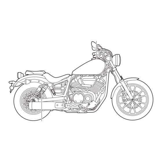
Description EAU32221 Left view Bolt 1. Headlight (page 7-30) 2. Owner’s tool kit (page 7-2) 3. Shock absorber assembly spring preload adjusting ring (page 4-13) 4. Fuses (page 7-29) 5. Engine oil drain bolt (page 7-11) 6. Shift pedal (page 4-7) 7. - Page 17 Description Bolt R-Spec 1. Headlight (page 7-30) 2. Owner’s tool kit (page 7-2) 3. Shock absorber assembly spring preload adjusting ring (page 4-13) 4. Fuses (page 7-29) 5. Engine oil drain bolt (page 7-11) 6. Shift pedal (page 4-7) 7. Engine oil filler cap (page 7-11)
-
Page 18: Right View
Description EAU32231 Right view Bolt 1. License plate light (page 7-32) 8. Steering lock (page 4-11) 2. Brake/tail light (page 7-31) 9. Engine oil filter cartridge (page 7-11) 3. Battery (page 7-27) 10.Rear brake light switch (page 7-20) 4. Rear brake fluid reservoir (page 7-21) 11.Brake pedal (page 4-8) 5. - Page 19 Description Bolt R-Spec 1. License plate light (page 7-32) 10.Rear brake light switch (page 7-20) 2. Brake/tail light (page 7-31) 11.Brake pedal (page 4-8) 3. Battery (page 7-27) 4. Rear brake fluid reservoir (page 7-21) 5. Air filter element (page 7-14) 6.
-
Page 20: Controls And Instruments
Description EAU10431 Controls and instruments 1. Clutch lever (page 4-7) 2. Left handlebar switches (page 4-5) 3. Multi-function meter unit (page 4-3) 4. Front brake fluid reservoir (page 7-21) 5. Right handlebar switches (page 4-5) 6. Brake lever (page 4-7) 7. -
Page 21: Instrument And Control Functions
Instrument and control functions EAU55831 EAU10542 EAU49399 Main switch Indicator lights and warning All electrical circuits are supplied with lights power; the meter lighting, taillight, li- 1 2 3 cense plate light and position lights come on, and the engine can be start- ed. - Page 22 This indicator light comes on when the detection circuit. If a problem is If this occurs, have a Yamaha dealer high beam of the headlight is switched detected in the oil level detection check the vehicle.
-
Page 23: Multi-Function Meter Unit
Instrument and control functions a clock EAU55815 Multi-function meter unit a self-diagnosis device This warning light will come on when the key is turned to “ON” and the start switch is pushed, but this does not in- The key must be turned to “ON” before dicate a malfunction. - Page 24 Instrument and control functions Odometer, tripmeters, fuel reserve Push the “SELECT” switch to change To set the clock tripmeter and clock the display between the odometer “ODO”, tripmeters 1 and 2 “TRIP 1” and “TRIP 2”, and the clock in the fol- lowing order: ODO →...
-
Page 25: Handlebar Switches
If a problem is detected in any of those circuits, the engine trouble warning light will come on and the display will indicate an error code. If the display indicates any error codes, note the code number and have a Yamaha dealer check the vehicle. - Page 26 Instrument and control functions Right has traveled both about 150 m (490 ft) EAU12713 Start switch “ ” and for approximately 15 seconds. Push this switch to crank the engine However, the turn signal lights can also with the starter. See page 6-1 for start- be canceled manually by pushing the ing instructions prior to starting the en- switch in after it has returned to the...
-
Page 27: Clutch Lever
Instrument and control functions EAU12822 EAU12872 EAU12892 Clutch lever Shift pedal Brake lever 1. Clutch lever 1. Shift pedal 1. Brake lever 2. Neutral position The clutch lever is located on the left The brake lever is located on the right The shift pedal is located on the left side of the handlebar. -
Page 28: Brake Pedal
Instrument and control functions 2. Turn the key counterclockwise to EAU12944 EAU13125 Brake pedal Fuel tank cap the original position, remove it, and then close the lock cover. The fuel tank cap cannot be installed unless the key is in the lock. In addi- tion, the key cannot be removed if the cap is not properly installed and locked. -
Page 29: Fuel
Gasoline is poisonous and can cau- hole. Stop filling when the fuel Your Yamaha engine has been de- se injury or death. Handle gasoline reaches the bottom of the filler signed to use regular unleaded gaso- with care. -
Page 30: Fuel Tank Breather/Overflow Hose
Yamaha because it easily burn. can cause damage to the fuel system 1. Fuel tank breather/overflow hose Park the vehicle in a place or vehicle performance problems. -
Page 31: Steering Lock
Instrument and control functions To unlock the steering ECA10702 EAU55663 Steering lock NOTICE The steering lock is located on the right Use only unleaded gasoline. The use side of the vehicle between the upper of leaded gasoline will cause unre- and lower steering brackets. -
Page 32: Rider Seat
Instrument and control functions EAU55822 Rider seat To remove the rider seat 1. Remove panel A. (See page 7-9.) 2. Remove the bolt. 1. Projection 1. Rubber damper 2. Seat holder Tightening torque: 2. Place the rider seat in the original Rider seat fitting bolt: position. -
Page 33: Adjusting The Shock Absorber Assemblies
Instrument and control functions soften the suspension, turn the adjust- EAU59232 Adjusting the shock absorber ing ring on each shock absorber as- Align the appropriate notch in the ad- assemblies sembly in direction (b). justing ring with the position indicator EWA10211 on the shock absorber. -
Page 34: Sidestand
EWA10232 EAU15306 Sidestand WARNING Yamaha dealer repair it if it does not The sidestand is located on the left These shock absorber assemblies function properly. side of the frame. Raise the sidestand contain highly pressurized nitrogen or lower it with your foot while holding gas. -
Page 35: Ignition Circuit Cut-Off System
Instrument and control functions EAU44893 Ignition circuit cut-off system The ignition circuit cut-off system (comprising the sidestand switch, clutch switch and neutral switch) has the following functions. It prevents starting when the transmission is in gear and the sidestand is up, but the clutch le- ver is not pulled. - Page 36 Instrument and control functions WARNING With the engine turned off: 1. Move the sidestand down. If a malfunction is noted, have a Yamaha 2. Make sure that the engine stop switch is set to “ ”. dealer check the system before riding.
-
Page 37: For Your Safety - Pre-Operation Checks
• If necessary, add recommended oil to specified level. 7-11 • Check vehicle for oil leakage. • Check operation. • If soft or spongy, have Yamaha dealer bleed hydraulic system. • Check brake pads for wear. Front brake • Replace if necessary. - Page 38 • Make sure that operation is smooth. • Check throttle grip free play. Throttle grip 7-15, 7-24 • If necessary, have Yamaha dealer adjust throttle grip free play and lubricate ca- ble and grip housing. • Make sure that operation is smooth. Control cables 7-23 •...
- Page 39 For your safety – pre-operation checks ITEM CHECKS PAGE • Check operation of ignition circuit cut-off system. 4-14 Sidestand switch • If system is not working correctly, have Yamaha dealer check vehicle.
-
Page 40: Operation And Important Riding Points
a lean angle sensor to stop the en- The transmission is in the neutral understand, ask your Yamaha dealer. gine in case of a turnover. In this EWA10272 position. -
Page 41: Shifting
NOTICE neutral position. The neutral indi- Even with the transmission in cator light should come on. If not, ask a Yamaha dealer to check the the neutral position, do not electrical circuit. coast for long periods of time 3. Start the engine by pushing the with the engine off, and do not start switch. -
Page 42: Engine Break-In
Operation and important riding points 4. At the recommended shift points 3. Shift the transmission into the EAU16842 Engine break-in shown in the following table, close neutral position when the motor- There is never a more important period the throttle, and at the same time, cycle almost completely... -
Page 43: Parking
If any engine trouble should occur WARNING during the engine break-in period, Since the engine and exhaust immediately have a Yamaha dealer system can become very hot, check the vehicle. park in a place where pedestri- ans or children are not likely to touch them and be burned. -
Page 44: Periodic Maintenance And Adjustment
To avoid possible burns, let tivities incorrectly may increase brake components cool before your risk of injury or death during touching them. service or while using the vehicle. If you are not familiar with vehicle ser- vice, have a Yamaha dealer perform service. -
Page 45: Owner's Tool Kits
Owner’s tool kits If you do not have the tools or ex- perience required for a particular job, have a Yamaha dealer per- form it for you. Install the owner’s tool box with the “INSIDE” mark facing inward. -
Page 46: Periodic Maintenance Chart For The Emission Control System
From 37000 km (24000 mi) or 36 months, repeat the maintenance intervals starting from 13000 km (8000 mi) or 12 months. Items marked with an asterisk require special tools, data and technical skills, have a Yamaha dealer perform the ser- vice. - Page 47 Periodic maintenance and adjustment INITIAL ODOMETER READINGS 1000 km 7000 km 13000 km 19000 km 25000 km 31000 km ITEM ROUTINE (600 mi) (4000 mi) (8000 mi) (12000 mi) (16000 mi) (20000 mi) 1 month 6 months 12 months 18 months 24 months 30 months •...
-
Page 48: General Maintenance And Lubrication Chart
30 months • Perform dynamic inspection us- Diagnostic system √ √ √ √ √ √ ing Yamaha diagnostic tool. check • Check the error codes. Air filter element • Replace. Every 37000 km (24000 mi) • Check operation. √ √... - Page 49 Periodic maintenance and adjustment INITIAL ODOMETER READINGS 1000 km 7000 km 13000 km 19000 km 25000 km 31000 km ITEM ROUTINE (600 mi) (4000 mi) (8000 mi) (12000 mi) (16000 mi) (20000 mi) 1 month 6 months 12 months 18 months 24 months 30 months •...
- Page 50 • Replace. tridge Front and rear √ √ √ √ √ √ 25 * • Check operation. brake switches • Apply Yamaha cable lubricant or √ √ √ √ √ √ 26 * Control cables other suitable cable lubricant thoroughly.
- Page 51 Periodic maintenance and adjustment INITIAL ODOMETER READINGS 1000 km 7000 km 13000 km 19000 km 25000 km 31000 km ITEM ROUTINE (600 mi) (4000 mi) (8000 mi) (12000 mi) (16000 mi) (20000 mi) 1 month 6 months 12 months 18 months 24 months 30 months •...
-
Page 52: Removing And Installing The Panel
Periodic maintenance and adjustment EAU18752 EAU42433 Removing and installing the Checking the spark plugs panel The spark plugs are important engine components, which are easy to check. The panel shown needs to be removed Since heat and deposits will cause any to perform some of the maintenance spark plug to slowly erode, the spark jobs described in this chapter. - Page 53 Do not attempt to with the spark plug wrench includ- diagnose such problems yourself. In- ed in the additional tool kit, which stead, have a Yamaha dealer check was handed out separately at the the vehicle. purchase of the vehicle.
-
Page 54: Engine Oil And Oil Filter Cartridge
Periodic maintenance and adjustment To install a spark plug EAU47115 Engine oil and oil filter car- 1. Clean the surface of the spark The engine oil should be between the tridge plug gasket and its mating surfa- minimum and maximum level marks. The engine oil level should be checked ce, and then wipe off any grime before each ride. - Page 55 An oil filter wrench is available at a cient oil of the recommended type Yamaha dealer. to raise it to the correct level. 5. Apply a thin coat of clean engine 6. Check the O-ring for damage, and oil to the O-ring of the new oil filter replace it if necessary.
- Page 56 Periodic maintenance and adjustment Recommended engine oil: See page 9-1. Oil quantity: Oil change: 3.70 L (3.91 US qt, 3.26 Imp.qt) With oil filter removal: 4.00 L (4.23 US qt, 3.52 Imp.qt) Be sure to wipe off spilled oil on any 1.
-
Page 57: Replacing The Air Filter Element
Yamaha dealer check chart. Replace the air filter element the vehicle. more frequently if you are riding in un- 12. -
Page 58: Checking The Throttle Grip Free Play
Therefore, it must be adjusted by a Yamaha dealer is essential to maintain the tires in good at the intervals specified in the periodic condition at all times and replace them maintenance and lubrication chart. - Page 59 * Total weight of rider, passenger, car- or glass fragments in it, or if the side- surface must first be “broken go and accessories wall is cracked, have a Yamaha dealer in” for it to develop its optimal replace the tire immediately. characteristics.
-
Page 60: Wheels
If any damage is found, have a Yamaha dealer replace the wheel. Do not attempt even the smallest repair to the wheel. A de- formed or cracked wheel must be replaced. -
Page 61: Adjusting The Clutch Lever Free
Spoke wheels before each ride. If any damage is found, have a Yamaha dealer re- place the wheel. Do not attempt even the smallest repair to the wheel. A deformed or cracked wheel must be replaced. -
Page 62: Checking The Brake Lever Free Play
1. No brake lever free play There should be no free play at the brake lever end. If there is free play, have a Yamaha dealer inspect the brake system. EWA14212 WARNING A soft or spongy feeling in the brake lever can indicate the presence of air in the hydraulic system. -
Page 63: Brake Light Switches
1. Brake pad wear indicator groove adjusted by a Yamaha dealer. Each front brake pad is provided with Turn the rear brake light switch adjust- wear indicator grooves, which allow... -
Page 64: Checking The Brake Fluid Level
Rear brake EAU22582 Checking the brake fluid level peared, have a Yamaha dealer replace Before riding, check that the brake fluid the brake pads as a set. is above the minimum level mark. Check the brake fluid level with the top... -
Page 65: Changing The Brake Fluid
EAU22733 Changing the brake fluid id; otherwise, the rubber seals Yamaha dealer check the cause before Have a Yamaha dealer change the further riding. may deteriorate, causing leak- brake fluid at the intervals specified in age. -
Page 66: Drive Belt Slack
To check the drive belt slack damaged or does not move smoothly, 1. Place the vehicle on the side- have a Yamaha dealer check or re- stand. place it. WARNING! Damage to the 2. Note the current position of the... -
Page 67: Checking And Lubricating The Throttle Grip And Cable
In pedals should be checked before each addition, the cable should be lubricat- ride, and the pedal pivots should be lu- ed by a Yamaha dealer at the intervals bricated if necessary. specified in the periodic maintenance Brake pedal chart. -
Page 68: Checking And Lubricating The Brake And Clutch Levers
EWA10732 Clutch lever WARNING If the sidestand does not move up and down smoothly, have a Yamaha dealer check or repair it. Otherwise, the sidestand could contact the ground and distract the operator, re- sulting in a possible loss of control. -
Page 69: Lubricating The Swingarm Pivots
The swingarm pivots must be lubricat- ce and hold it in an upright posi- fork does not operate smoothly, ed by a Yamaha dealer at the intervals tion. WARNING! To avoid injury, have a Yamaha dealer check or re- specified in the periodic maintenance securely support the vehicle so pair it. -
Page 70: Checking The Steering
If any free This model is equipped with a VRLA smoothly, have a Yamaha dealer play can be felt, have a Yamaha (Valve Regulated Lead Acid) battery. check the wheel bearings. dealer check or repair the steer- There is no need to check the electro- ing. - Page 71 To charge the battery ge it if necessary. Have a Yamaha dealer charge the bat- 3. Fully charge the battery before installation. NOTICE: When in- tery as soon as possible if it seems to have discharged.
-
Page 72: Replacing The Fuses
Periodic maintenance and adjustment EAU55673 Replacing the fuses The main fuse, the fuel injection sys- tem fuse, and the fuse box, which con- tains the fuses for the individual circuits, are located under the owner’s tool box behind panel A. (See page 7-9.) 1. -
Page 73: Replacing The Headlight Bulb
4. If the fuse immediately blows again, have a Yamaha dealer check the electrical system. 1. Headlight coupler 2. Headlight bulb cover 1. Do not touch the glass part of the bulb. -
Page 74: Brake/Tail Light
6. Install the headlight unit by install- position, and then secure it with ing the screws. the bulb holder. 7. Have a Yamaha dealer adjust the 5. Install the bulb cover, and then headlight beam if necessary. connect the coupler. -
Page 75: Replacing A Turn Signal Light Bulb
Replacing a turn signal light License plate light bulb If the license plate light does not come on, have a Yamaha dealer check the 1. Remove the turn signal light lens electrical circuit or replace the bulb. by removing the screws. -
Page 76: Supporting The Motorcycle
However, should your motorcycle To service the front wheel require any repair, take it to a Yamaha 1. Stabilize the rear of the motorcy- dealer, whose skilled technicians have cle by using a motorcycle stand... - Page 77 Periodic maintenance and adjustment heaters or furnaces. Gasoline or gasoline vapors can ignite or ex- plode, causing severe injury or prop- erty damage. 7-34...
-
Page 78: Troubleshooting Chart
Remove the spark plugs and check the electrodes. The engine does not start. Have a Yamaha dealer check the vehicle. Check the compression. 4. Compression The engine does not start. There is compression. -
Page 79: Motorcycle Care And Storage
Some models are equipped with matte colored finished parts. Be ble. Rust and corrosion can develop Cleaning sure to consult a Yamaha dealer for even if high-quality components are ECA10773 NOTICE used. A rusty exhaust pipe may go un-... - Page 80 Motorcycle care and storage off any detergent residue using shield. Test the product on a plenty of water, as it is harmful small hidden part of the wind- Salt sprayed on roads in the winter to plastic parts. shield to make sure that it does may remain well into spring.
-
Page 81: Storage
Contaminants on the brakes or tires of the presence of ammonia) can cause loss of control. Consult a Yamaha dealer for ad- and areas where strong chemi- Make sure that there is no oil or vice on what products to use. - Page 82 Motorcycle care and storage 2. Fill up the fuel tank and add fuel e. Remove the spark plug caps stabilizer (if available) to prevent from the spark plugs, and then Make any necessary repairs before the fuel tank from rusting and the install the spark plugs and the storing the motorcycle.
-
Page 83: Specifications
Specifications Dimensions: Compression ratio: Fuel: 9.0 : 1 Overall length: Recommended fuel: Starting system: 2290 mm (90.2 in) Regular unleaded gasoline (Gasohol [E10] Electric starter Overall width: acceptable) Lubrication system: 830 mm (32.7 in) Fuel tank capacity: Wet sump Overall height: 13 L (3.4 US gal, 2.9 Imp.gal) Engine oil: 1120 mm (44.1 in) - Page 84 Specifications 3rd: Manufacturer/model: Rim size: 1.579 (30/19) BRIDGESTONE/EXEDRA G722 F (Cast 16M/C x MT3.50 4th: wheel) Front brake: 1.259 (34/27) BRIDGESTONE/EXEDRA G722 L (Spoke Type: 5th: wheel) Hydraulic single disc brake 1.042 (25/24) Loading: Specified brake fluid: Chassis: Maximum load: DOT 4 Frame type: 205 kg (452 lb)
- Page 85 Specifications Ignition system: Fuel level warning light: Charging system: Engine trouble warning light: AC magneto Battery: Fuse(s): Model: Main fuse: YTZ14S 40.0 A Voltage, capacity: Headlight fuse: 12 V, 11.2 Ah (10 HR) 20.0 A Headlight: Taillight fuse: 7.5 A Bulb type: Signaling system fuse: Halogen bulb...
-
Page 86: Consumer Information
Vehicle identification number ed when registering the vehicle with the authorities in your area and when EAU26442 Engine serial number ordering spare parts from a Yamaha dealer. VEHICLE IDENTIFICATION NUMBER: 1. Vehicle identification number ENGINE SERIAL NUMBER: The vehicle identification number is 1. - Page 87 This label shows specifica- will be needed when ordering spare key. tions related to exhaust emissions as parts from a Yamaha dealer. required by federal law, state law and Environment Canada. 10-2...
-
Page 88: Maintenance Record
Consumer information EAU26643 Maintenance record Copies of work orders and/or receipts for parts purchased and installed on your vehicle will be required to document that maintenance has been completed in accordance with the emissions warranty. The chart below is printed only as a reminder that maintenance work is required. - Page 89 Consumer information Maintenance Date of Servicing dealer Mileage Remarks interval service name and address 55000 km (36000 mi) or 54 months 61000 km (40000 mi) or 60 months 10-4...
-
Page 90: Yamaha Motor Canada Ltd
In this warranty, the term ‘MOTORCYCLE’ shall refer to a new or YZ, with the exception of WR25R, WR25X and YZ85 change of registration is sent to YAMAHA at the time of such motorcycle manufactured by YAMAHA MOTOR COMPANY, LTD. - Page 91 CUSTOMER at the time of DELIVERY. fitness for a particular purpose on the part of YAMAHA, and any other obligation or liability on behalf of YAMAHA, and the above...
-
Page 92: Index
Index Fuel level warning light ......4-2 Part locations ..........3-1 Fuel tank breather/overflow hose..4-10 Air filter element, replacing ....7-14 Fuel tank cap.......... 4-8 RESET switch .........4-6 Fuses, replacing ........7-29 Rider seat..........4-12 Battery ..........7-27 Brake and clutch levers, checking and Handlebar switches........ - Page 93 Index Valve clearance ........7-15 Vehicle Emission Control Information label............ 10-2 Vehicle identification number ....10-1 Warranty ..........10-5 Wheel bearings, checking ....7-27 Wheels..........7-17 11-2...
- Page 95 Yamalube – Take care of your Yamaha with legendary Yamalube oils, lubricants, and care products. They’re formulated and approved by the toughest judges we know: the Yamaha engineering teams that know your Yamaha from the inside out.
- Page 96 PRINTED ON RECYCLED PAPER PRINTED IN JAPAN 2016.07-0.3×1 CR...
Need help?
Do you have a question about the Bolt XVS95CH and is the answer not in the manual?
Questions and answers
why is first gear knocking
The first gear knocking on a Yamaha XVS95CH may be caused by improper shifting technique or engaging gears too slowly, especially when changing gears takes more than 10 seconds, which can damage the engine, transmission, or drivetrain. It may also occur if the engine is cold and hard acceleration is applied.
This answer is automatically generated
How do I put the gas tank cap on?
To install the gas tank cap on a Yamaha XVS95CH:
1. Insert the fuel tank cap into the tank opening with the key inserted in the lock.
2. Make sure the "▲" mark on the cap is facing forward.
3. Press down and turn the key to lock the cap.
4. Close the fuel tank cap lock cover.
Note: The key must be in the lock to install the cap, and it cannot be removed unless the cap is properly installed and locked.
This answer is automatically generated