Table of Contents
Advertisement
Quick Links
Advertisement
Table of Contents

Related Manuals for Siemens SIMATIC EP200SP


Summary of Contents for Siemens SIMATIC EP200SP
- Page 2 ___________________ Preface ___________________ Documentation guide ___________________ SIMATIC Product overview ___________________ Wiring ET 200SP Digital output module ___________________ DQ 8x24VDC/0.5A SNK BA Parameters/address space (6ES7132-6BF61-0AA0) ___________________ Interrupts/diagnostics alarms Manual ___________________ Technical specifications ___________________ Parameter data record 09/2017 A5E32855878-AB...
- Page 3 Note the following: WARNING Siemens products may only be used for the applications described in the catalog and in the relevant technical documentation. If products and components from other manufacturers are used, these must be recommended or approved by Siemens. Proper transport, storage, installation, assembly, commissioning, operation and maintenance are required to ensure that the products operate safely and without any problems.
-
Page 4: Preface
Purpose of the documentation This manual supplements the system manual ET 200SP distributed I/O system (http://support.automation.siemens.com/WW/view/en/58649293). Functions that generally relate to the system are described in this manual. The information provided in this manual and in the system/function manuals supports you in commissioning the system. - Page 5 Siemens' products and solutions undergo continuous development to make them more secure. Siemens strongly recommends that product updates are applied as soon as they are available and that the latest product versions are used. Use of product versions that are no longer supported, and failure to apply the latest updates may increase customers' exposure to cyber threats.
-
Page 6: Table Of Contents
Table of contents Preface ..............................4 Documentation guide ..........................7 Product overview ..........................11 Properties ..........................11 Wiring ..............................13 Wiring and block diagram ...................... 13 Parameters/address space ........................15 Parameters ..........................15 Explanation of parameters ..................... 16 Address space ........................17 Interrupts/diagnostics alarms......................... -
Page 7: Documentation Guide
Documentation guide The documentation for the SIMATIC ET 200SP distributed I/O system is arranged into three areas. This arrangement enables you to access the specific content you require. Basic information The system manual describes in detail the configuration, installation, wiring and commissioning of the SIMATIC ET 200SP. - Page 8 You need to register once to use the full functionality of "mySupport". You can find "mySupport" in the Internet (https://support.industry.siemens.com/My/ww/en). "mySupport" - Documentation In the Documentation area of "mySupport", you have the possibility to combine complete manuals or parts of them to make your own manual.
- Page 9 ● Manuals, characteristics, operating manuals, certificates ● Product master data You can find "mySupport" - CAx Data in the Internet (http://support.industry.siemens.com/my/ww/en/CAxOnline). Application examples The application examples support you with various tools and examples for solving your automation tasks. Solutions are shown in interplay with multiple components in the system - separated from the focus in individual products.
- Page 10 You can find the SIMATIC Automation Tool on the Internet (https://support.industry.siemens.com/cs/ww/en/view/98161300). PRONETA With SIEMENS PRONETA (PROFINET network analysis), you analyze the plant network during commissioning. PRONETA features two core functions: ● The topology overview independently scans PROFINET and all connected components.
-
Page 11: Product Overview
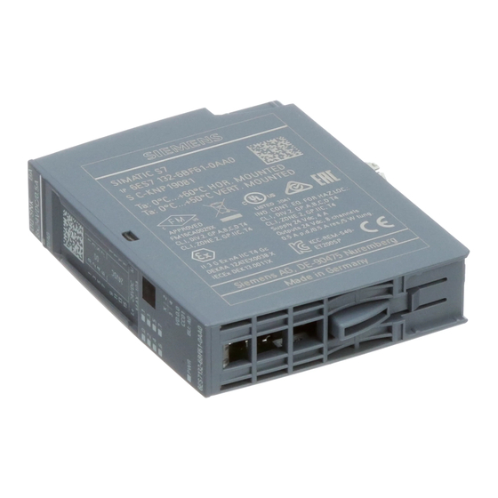
Product overview Properties Part number 6ES7132-6BF61-0AA0 View of the module ① ⑦ Module type and name Function class ② ⑧ LED for diagnostics Color coding module type ③ ⑨ 2D matrix code Function and firmware version ④ ⑩ Wiring diagram Color code for selecting the color identification labels ⑤... - Page 12 ● Color identification labels ● Reference identification label ● Shield connector See also You can find additional information on the accessories in the ET 200SP Distributed I/O System (http://support.automation.siemens.com/WW/view/en/58649293) system manual. Digital output module DQ 8x24VDC/0.5A SNK BA (6ES7132-6BF61-0AA0) Manual, 09/2017, A5E32855878-AB...
-
Page 13: Wiring
This section includes the block diagram of the DQ 8x24VDC/0.5A SNK BA module with the terminal assignments for a 1-wire and 2-wire connection. Information about wiring of the BaseUnit is available in the system manual ET 200SP distributed I/O system (http://support.automation.siemens.com/WW/view/en/58649293). Note You may use and combine the different wiring options for all channels. - Page 14 Wiring 3.1 Wiring and block diagram Connection: 1-wire and 2-wire connection The following figure shows the block diagram and an example of the terminal assignment of the digital input module DQ 8x24VDC/0.5A SNK BA on the BaseUnit BU type A0 without AUX terminals (1-wire and 2-wire connection).
-
Page 15: Parameters/Address Space
Parameters/address space Parameters DQ 8x24VDC/0,5A SNK BA parameters Specify the module properties with the various parameters in the course of your STEP 7 configuration. The following table lists the configurable parameters. The effective range of the configurable parameters depends on the type of configuration. The following configurations are possible: ●... -
Page 16: Explanation Of Parameters
A potential group ends with the dark-colored BaseUnit, which follows a light-colored BaseUnit or server module in the station configuration. See also ET 200SP distributed I/O system (http://support.automation.siemens.com/WW/view/en/58649293) Digital output module DQ 8x24VDC/0.5A SNK BA (6ES7132-6BF61-0AA0) Manual, 09/2017, A5E32855878-AB... -
Page 17: Address Space
Parameters/address space 4.3 Address space Address space The module can be configured differently in STEP 7; see following table. Depending on the configuration, additional/different addresses are assigned in the process image of the inputs. Configuration options of DQ 8x24VDC 0.5A SNK BA You can configure the module with STEP 7 (TIA Portal) or with a GSD file. -
Page 18: Interrupts/Diagnostics Alarms
Interrupts/diagnostics alarms Status and error displays LED displays The figure below shows the LED displays (status and error displays) of the DQ 8x24VDC/0,5A SNK BA. ① DIAG (green/red) ② Channel status (green) ③ PWR (green) Figure 5-1 LED displays Meaning of the LED displays The tables below explain the meaning of the Status and error displays. - Page 19 Interrupts/diagnostics alarms 5.1 Status and error displays LED channel status Table 5- 2 Status display of the LED channel status LED channel Meaning status Channel deactivated or activated and process signal = 0 Channel activated and process signal = 1 LED PWR Table 5- 3 Status display of the LED PWR...
-
Page 20: Interrupts
Interrupts/diagnostics alarms 5.2 Interrupts Interrupts The DQ 8×24VDC/0,5A SNK BA digital output module supports diagnostics alarms. Diagnostics interrupts The module generates a diagnostic interrupt at the following event: ● Parameter assignment error ● No supply voltage Detailed information on the event is available in the STEP 7 online help. Diagnostics alarms Diagnostics alarms A diagnostic alarm is generated and the DIAG-LED flashes on the module for each... -
Page 21: Technical Specifications
Technical specifications Technical specifications Technical specifications of the DQ 8×24VDC/0,5A SNK BA Article number 6ES7132-6BF61-0AA0 General information Product type designation DQ 8x 24 V DC/0.5 A SNK BA, PU 1 Firmware version V0.0 FW update possible • usable BaseUnits BU type A0 Color code for module-specific color identifica- CC01 tion plate... - Page 22 Technical specifications 6.1 Technical specifications Article number 6ES7132-6BF61-0AA0 Output voltage Rated value (DC) 24 V Power loss Power loss, typ. 1.5 W Address area Address space per module 1 byte Outputs • Hardware configuration Automatic encoding Mechanical coding element • Digital outputs Type of digital output Source output (PNP, current-sourcing)
- Page 23 Technical specifications 6.1 Technical specifications Article number 6ES7132-6BF61-0AA0 Switching frequency 100 Hz with resistive load, max. • 0.5 Hz with inductive load, max. • 10 Hz on lamp load, max. • Total current of the outputs 0.5 A Current per channel, max. •...
- Page 24 2 000 m Dimensions Width 15 mm Height 73 mm Depth 58 mm Weights Weight, approx. 30 g Dimensional drawing See the manual ET 200SP BaseUnits (http://support.automation.siemens.com/WW/view/en/58532597/133300) Digital output module DQ 8x24VDC/0.5A SNK BA (6ES7132-6BF61-0AA0) Manual, 09/2017, A5E32855878-AB...
-
Page 25: Parameter Data Record
Parameter data record Parameter assignment and structure of parameter data record The data record of the module has an identical structure, regardless of whether you configure the module with PROFIBUS DP or PROFINET IO. With data record 128, you can reconfigure the module in your user program regardless of your programming. - Page 26 Parameter data record A.1 Parameter assignment and structure of parameter data record Structure of data record 128 Note Channel 0 includes the diagnostics for the entire module. Figure A-1 Structure of data record 128 Header information The figure below shows the structure of the header information. Figure A-2 Header information Digital output module DQ 8x24VDC/0.5A SNK BA (6ES7132-6BF61-0AA0)
- Page 27 Parameter data record A.1 Parameter assignment and structure of parameter data record Parameters The figure below shows the structure of the parameters for channels 0 to 7. Enable a parameter by setting the corresponding bit to "1". Figure A-3 Structure byte x to x+1 for the channels 0 to 7 Digital output module DQ 8x24VDC/0.5A SNK BA (6ES7132-6BF61-0AA0) Manual, 09/2017, A5E32855878-AB...
- Page 28 Parameter data record A.1 Parameter assignment and structure of parameter data record Error transferring the data record The module always checks all the values of the transferred data record. Only if all the values were transferred without errors does the module apply the values from the data record. The WRREC instruction for writing data records returns corresponding error codes when errors occur in the STATUS parameter.
Need help?
Do you have a question about the SIMATIC EP200SP and is the answer not in the manual?
Questions and answers