
Subscribe to Our Youtube Channel
Related Manuals for McQuay MFU-C


Summary of Contents for McQuay MFU-C
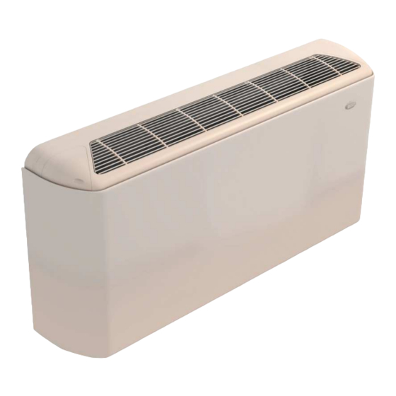
- Page 1 PRODUCT MANUAL PRODUCT MANUAL PRODUCT MANUAL PRODUCT MANUAL Chilled Water Vertical Fan Coils Models: MFU-C MFU-H MFC-C MFC-H...
-
Page 2: Table Of Contents
The unit must be GROUNDED to prevent possible hazard due to insulation failure. Confirm that the unit has been switched OFF before installing or servicing the unit. CHILLED WATER FAN COILS – McQuay... - Page 3 Activating all parameters and routines of regulation which optimise the operation of the unit. Through AC2800 units can also be directly integrated with Smart Manager, McQuay solution for the supervision of hydronic systems. With reference to fan coils, Smart Manager run up to 50 mini-chillers and 120 fan coils.
-
Page 4: General Characteristics
4) The room sensor failure alarm: high speed LED blinks and shuts off all outputs. The water sensor failure alarm: medium speed LED blinks and shuts off all outputs. 5) Mode conflict: the mode LED blinks and shuts off all outputs. Smart manager integration CHILLED WATER FAN COILS – McQuay... - Page 5 At the same time, the system will shut off all outputs and the mode LED will blink. 2. For 4-pipes model, the water sensor is fixed on the pipe of hot water. CHILLED WATER FAN COILS – McQuay...
- Page 6 Across AC2800, the units can be connected straight to Smart Manager, the McQuay hydronic systems supervision solution. With reference to hydronic units, Smart Manger manages up to 50 mini-chillers and 120 fan coils.
- Page 7 Easy utilization, allows to set essential operating parameter: room temperature, fan speed, ON/OFF ACCESSORIES Valves kit [standard condensate drain panel], 2 or 3 ways Electrical heater (optional) Controllers (optional) Feet (cover and/or support) Base module Frontal air intake module External air intake module CHILLED WATER FAN COILS – McQuay...
-
Page 8: Technical Data
3 At High/Medium/Low speed; nominal air flow; measured in a room of 100m volume and 0.5 sec. reverberation time (e.g. office/conference room with carpet on the floor) 4 Nominal Air Flow; High Fan Speed CHILLED WATER FAN COILS – McQuay... - Page 9 6 At the following nominal conditions: nominal air flow; 70/60 ° C inlet/outlet water temperature; 20° C inlet air temperature; High speed 7 At High/Medium/Low speed; nominal air flow; measured in a room of 100 m volume and 0.5 sec. reverberation time (e.g. office/conference room with carpet on the floor) CHILLED WATER FAN COILS – McQuay...
- Page 10 28.8 43.4 45.7 47.7 46.8 40.8 35.4 61.0 52.6 47.0 490C Medium 18.9 26.9 40.7 43.6 45.3 44.1 37.8 31.8 58.1 50.1 45.0 16.8 24.5 37.7 40.9 41.9 40.3 33.5 27.1 55.0 46.8 42.0 CHILLED WATER FAN COILS – McQuay...
- Page 11 40.9 41.9 40.3 33.5 27.1 55.0 46.8 42.0 Sound pressure level and NR are measured to a room of 100m³ volume and 0.5 sec. reverberation time (e.g. office/conference room with carpet on the floor). CHILLED WATER FAN COILS – McQuay...
-
Page 12: Operating Limits And Pressure Drops
Water Flow* [l/s] Water Flow* [l/s] Water Flow* [l/s] Water Flow* [l/s] Water Flow* [l/s] Water Flow* [l/s] Water Flow* [l/s] *The pressure drop is for coil only and excludes water connections and valves. CHILLED WATER FAN COILS – McQuay... -
Page 13: Outlines And Dimensions
WATER INLET CONDENSATE DRAIN PAN CONDENSATE DRAIN PAN CONDENSATE DRAIN PAN (CONNECTIONS AND (CONNECTIONS AND (CONNECTIONS AND VALVES) VALVES) VALVES) WLWCTRIC BOX WLWCTRIC BOX WLWCTRIC BOX FIXING SLOTS FIXING SLOTS FIXING SLOTS FILTER FILTER FILTER CHILLED WATER FAN COILS – McQuay... - Page 14 480 /490 1110 1310 1510 558.6 mm 100 mm Height = 100 mm from the wall for: - Feet (cover and/or support) - Base module - Frontal air intake module - External air intake module CHILLED WATER FAN COILS – McQuay...
-
Page 15: Installation
M F C ---- ---- 2 E A 4 E A ---- ---- Accessory installation of MFU/MFC unit 1) Before installation, lay down the unit with cabinet upwards; 2) Step one : Install the SUPPORT; CHILLED WATER FAN COILS – McQuay... - Page 16 As shown as the above drawings, to drill the screw to fix the support with core units; 3) Step two: To install the AESTHETIC FEET (L/R); MFU UNIT MFU UNIT AESTHETIC FEET R AESTHETIC FEET R SUPPORT SUPPORT CHILLED WATER FAN COILS – McQuay...
- Page 17 INLET GRILLE To fix the grille please slot the grille into the fixing screw (shown as the above view) , to adjust the tightness of screw and ensure the rotate of grille fixed with screw; CHILLED WATER FAN COILS – McQuay...
- Page 18 Do not put any object which may become obstacle for the air flow into or out the unit. The location must not be susceptible to high concentration dust, oil, salt or sulfide gas. MFC Series All units MIN. DISTANCE(mm) MFU Series All units MIN. DISTANCE(mm) CHILLED WATER FAN COILS – McQuay...
-
Page 19: Control Features
Potentiometer for temperature regulation On/Off keys On/Off led Heating / Cooling mode keys Heating / Cooling mode led Fan Speed selection keys Fan Speed led (HIGH) Fan Speed led (MEDIUM) Fan Speed led (LOW) CHILLED WATER FAN COILS – McQuay... -
Page 20: Electronic Controller Ac2800
Potentiometer for temperature regulation On/Off keys On/Off led Heating / Cooling mode keys Heating / Cooling mode led Fan Speed selection keys Fan Speed led (HIGH) Fan Speed led (MEDIUM) Fan Speed led (LOW) CHILLED WATER FAN COILS – McQuay... - Page 21 25°C, or when the system works on heat mode and the water temperature is blow 25° C, t he system conside it as the mode conflict, at the same time, the system will shut off all outputs and the LED will blink.) CHILLED WATER FAN COILS – McQuay...
- Page 22 Clock/Timer setting Fan Speed selection key (HIGH/MEDIUM/LOW) Temperature up key Temperature down key Back-light LCD Display On/Off key Fan Speed selection key (HIGH/MEDIUM/LOW) Temperature up key Temperature down key Heating/Cooling mode key Clock/Timer setting CHILLED WATER FAN COILS – McQuay...
- Page 23 AUTO-DIAGNOSIS E00: Ambient temperature sensor open E01: Ambient temperature sensor short CHILLED WATER FAN COILS – McQuay...
-
Page 24: Mechanical Thermostat Ac512/Ac513
Main Functions On/Off Cool/Heat Mode Fan Speed (HIGH/MEDIUM/LOW) 2 or 3 ways valve with ON/OFF control Integration into FCU Network Integration with Smart Manager Potentiometer for temperature regulation Fan speed keys (HIGH/MEDIUM/LOW) Heating/Cooling mode buttons CHILLED WATER FAN COILS – McQuay... -
Page 25: Wiring Diagrams
412 / 420 / 425 / 435 / 450 / 460 / 480 / 490 MFU – H0 – BCE 012 / 020 / 025 / 035 / 050 / 060 / 080 / 090 CHILLED WATER FAN COILS – McQuay... - Page 26 412 / 420 / 425 / 435 / 450 / 460 / 480 / 490 MFU – H0 – BCM 012 / 020 / 025 / 035 / 050 / 060 / 080 / 090 CHILLED WATER FAN COILS – McQuay...
-
Page 27: Technical Data At Conditions Non Standard
2.47 2.29 0.25 0.25 0.38 0.38 0.49 0.49 0.74 0.74 1.23 1.213 1.65 1.65 1.91 1.88 2.23 2.06 0.22 0.22 0.30 0.30 0.40 0.40 0.59 0.59 0.92 0.92 1.32 1.32 1.53 1.50 1.78 1.65 CHILLED WATER FAN COILS – McQuay... - Page 28 4.23 3.91 0.54 0.54 0.74 0.74 0.82 0.92 1.40 1.40 2.08 2.08 2.78 2.78 3.22 3.17 3.75 3.48 0.46 0.46 0.58 0.58 0.73 0.73 1.08 1.08 1.52 1.52 2.20 2.20 2.55 2.51 2.97 2.75 CHILLED WATER FAN COILS – McQuay...
- Page 29 7.92 5.30 1.05 0.80 1.41 1.06 2.00 1.25 2.94 1.93 4.14 2.76 5.33 3.73 6.18 4.25 7.20 4.66 0.90 0.67 1.13 0.81 1.55 0.98 2.26 1.47 3.07 1.98 4.33 2.89 5.02 3.29 5.85 3.61 CHILLED WATER FAN COILS – McQuay...
- Page 30 2.70 2.43 0.32 0.32 0.52 0.52 0.69 0.69 0.87 0.87 1.37 1.37 1.86 1.86 2.06 2.06 2.42 2.18 0.27 0.27 0.43 0.43 0.55 0.55 0.67 0.67 1.03 1.03 1.48 1.48 1.64 1.64 1.92 1.73 CHILLED WATER FAN COILS – McQuay...
- Page 31 4.49 4.04 0.61 0.61 0.96 0.96 1.29 1.14 1.57 1.57 2.25 2.25 3.06 3.06 3.40 3.40 3.98 3.58 0.52 0.52 0.77 0.77 1.02 0.90 1.18 1.18 1.70 1.65 2.40 2.40 2.66 2.66 3.12 2.81 CHILLED WATER FAN COILS – McQuay...
- Page 32 8.41 5.34 1.31 1.84 1.81 1.33 2.49 1.47 2.11 2.11 4.62 2.91 5.84 4.01 6.48 4.45 7.59 4.69 1.10 0.71 1.49 1.04 1.94 1.15 1.56 1.56 3.38 2.10 4.67 3.08 5.18 3.42 6.07 3.60 CHILLED WATER FAN COILS – McQuay...
- Page 33 McQuay Italia S.p.A. S.S. Nettunense, km 12+300 – 00040 Cecchina (Roma) – Italia tel. +39 06 937311; fax +39 06 9374014; e-mail mcquay@mcquayitalia.com www.mcquayeurope.com info@mcquayeurope.com CHILLED WATER FAN COILS – McQuay...
Need help?
Do you have a question about the MFU-C and is the answer not in the manual?
Questions and answers