
Related Manuals for McQuay MCC 010C/CR


Summary of Contents for McQuay MCC 010C/CR
- Page 1 Your Climate. We're There. TM: MCC-CR-2200B Ceiling Concealed Fan Coil Unit Models: MCC 010C/CR MCC 030C/CR MCC 015C/CR MCC 040C/CR MCC 020C/CR MCC 050C/CR MCC 025C/CR MCC 060C/CR ® Air Conditioning REGISTERED...
-
Page 2: Table Of Contents
"McQuay" is a registered trademark of McQuay International. All rights reserved throughout the world. ©2001 McQuay International "Bulletin illustrations cover the general appearance of McQuay International products at the time of publication and we reserve the right to make changes in design and construction at any time without notice."... -
Page 3: Features
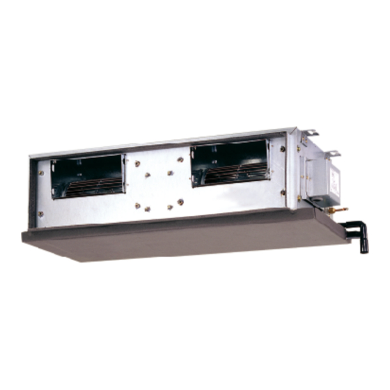
Features Features Space Saving, Elegance and Prestige The unit is installed above the ceiling with only the supply and return air grille exposed to view. This ceiling concealed type of design has made it an “Evergreen” model without sacrificing the precious floor space. The air-conditioned space will appear as elegant and prestigious as centralized air-conditioned area but with only a fraction of the cost. -
Page 4: Specifications
Specifications Specifications CEILING CONCEALED COOLING ONLY MODELS MODEL INDOOR UNIT MCC 010C MCC 015C MCC 020C MCC 025C OUTDOOR UNIT MLC 010B MLC 015B MLC 020B MLC 025B NOMINAL kcal/h 2,444 3,200 4,914 6,300 COOLING 2,843 3,722 5,715 7,327 CAPACITY Btu/h 9,700 12,700... - Page 5 CEILING CONCEALED COOLING ONLY MODELS MODEL INDOOR UNIT MCC 030C MCC 040C MCC 050C MCC 060C OUTDOOR UNIT MLC 030B MLC 030C MLC 040C MLC 050C MLC 060C MMC 060C NOMINAL kcal/h 7056 7560 10080 12600 15120 15120 COOLING 8204 8790 11720 14650...
- Page 6 CEILING CONCEALED HEAT PUMP MODELS MODEL INDOOR UNIT MCC 010CR MCC 015CR MCC 020CR MCC 025CR OUTDOOR UNIT MLC 010BR MLC 015BR MLC 020BR MLC 025BR NOMINAL kcal/h 2,394 3,200 4,788 5,796 COOLING 2,784 3,722 5,569 6,741 CAPACITY Btu/h 9,500 12,700 19,000 23,000...
- Page 7 CEILING CONCEALED HEAT PUMP MODELS MODEL INDOOR UNIT MCC 060CR MCC 030CR MCC 040CR MCC 050CR OUTDOOR UNIT MLC 030CR MLC 040CR MLC 050CR MLC 060CR MMC 060CR NOMINAL kcal/h 7560 10080 12600 14620 14620 COOLING 8790 11720 14650 16990 16990 CAPACITY Btu/h...
- Page 8 CEILING CONCEALED COOLING ONLY MODELS (R407C) MODEL INDOOR UNIT MCC 010C MCC 015C MCC 020C MCC 025C OUTDOOR UNIT M4LC 010B M4LC 015B M4LC 020B M4LC 025B NOMINAL kcal/h 2,268 2,772 4,612 5,292 COOLING 2,637 3,223 5,363 6,155 CAPACITY Btu/h 9,000 11,000 18,300...
- Page 9 CEILING CONCEALED COOLING ONLY MODELS (R407C) MODEL INDOOR UNIT MCC 030C MCC 040C MCC 050C OUTDOOR UNIT M4LC 030C M4LC 040C M4LC 050C NOMINAL kcal/h 7,560 9,576 12,600 COOLING 8,790 11,134 14,650 CAPACITY Btu/h 30,000 38,000 50,000 POWER SOURCE V/Ph/Hz 220 - 240 / 1 / 50 REFRIGERANT / CONTROL R407C / CAPILLARY TUBE (INDOOR)
- Page 10 CEILING CONCEALED HEAT PUMP MODELS (R407C) MODEL INDOOR UNIT MCC 010CR MCC 015CR MCC 020CR MCC 025CR OUTDOOR UNIT M4LC 010BR M4LC 015BR M4LC 020BR M4LC 025BR NOMINAL kcal/h 2,268 2,772 4,536 5,170 COOLING 2,637 3,223 5,274 6,008 CAPACITY Btu/h 9,000 11,000 18,000...
- Page 11 CEILING CONCEALED HEAT PUMP MODELS (R407C) MODEL INDOOR UNIT MCC 030CR MCC 040CR MCC 050CR OUTDOOR UNIT M4LC 030CR M4LC 040CR M4LC 050CR NOMINAL kcal/h 7,310 9,830 12,100 COOLING 8,499 11,430 14,068 CAPACITY Btu/h 29,000 39,000 48,000 NOMINAL kcal/h 7,812 10,332 12,600 HEATING...
-
Page 12: Noise Level
Noise Level Noise Level 1/1 Octave A-weighed sound pressure level (dBA), ref 20 µPa Model 125 Hz 250 Hz 500 Hz 1 kHz 2 kHz 4 kHz 8 kHz Ave. MCC 010 C/CR MCC 015 C/CR MCC 020 C/CR MCC 025 C/CR MCC 030 C/CR MCC 040 C/CR MCC 050 C/CR... -
Page 13: Performance Table
Performance Table Model : MCC010C/MLC010B Indoor DB Indoor WB Capacity Outdoor DB, ° C ° C ° C 19.4 2.532 2.424 2.328 2.231 2.134 2.018 26.7 13.9 2.532 2.424 2.328 2.231 2.134 2.018 2.765 2.617 2.485 2.353 2.221 2.063 2.492 2.382 2.284 2.185... - Page 14 Model : MCC020C/MLC020B Indoor DB Indoor WB Capacity Outdoor DB, ° C ° C ° C 19.4 26.7 13.9 5.264 5.010 4.783 4.556 4.330 4.058 4.788 4.634 4.497 4.360 4.223 4.058 5.607 5.313 5.051 4.788 4.526 4.211 4.749 4.585 4.439 4.292 4.146 3.970...
-
Page 15: Fan Performance Curve
Fan Performance Curves Fan Performance Curves External Static Pressure (mmAq) Model Fan Speed (CFM) MCC010C High Medium MCC015C High Medium MCC020C High Medium MCC025C High 1060 1023 Medium Model : MCC030C Model : MCC040C... - Page 16 Model : MCC050C Model : MCC060C...
-
Page 17: Outlines And Dimensions
Outlines and dimensions Indoor Unit Model : MCC010 C/CR All dimensions are in mm Model : MCC015 ~ 025 C/CR All dimensions are in mm Model MCC015C/CR 881.0 225.0 842.0 802.0 261.0 411.0 351.0 905.0 MCC020C/CR 1041.0 225.0 1002.0 962.0 261.0 411.0 351.0... - Page 18 Model : MCC030 ~ 060 C/CR All dimensions are in mm Model MCC030 C/CR 929.0 999.0 956.0 917.0 408.5 378.0 541.0 256.0 173.0 311.0 70.5 MCC040 C/CR 1045.0 1115.0 1072.0 1033.0 466.5 378.0 541.0 256.0 173.0 311.0 128.5 MCC050 C/CR 1299.0 1369.0 1326.0...
- Page 19 Outdoor Unit Model : MLC 010 / 015 B/BR M4LC 010 / 015 B/BR Note : Dimension in mm Model : MLC 020 / 025 B/BR, MLC 030B M4LC 020 / 025 B/BR Note : Dimension in mm...
- Page 20 Model : 030 / 040 / 050 / 060 C/CR M4LC 030 / 040 / 050 C/CR Note : Dimension in mm Model : MMC 060 C/CR Note : Dimension in mm...
-
Page 21: Wiring Diagrams
Wiring diagrams Wiring diagrams Model : MCC 010C / 015C – MLC/M4LC 010B / 015B (For export spec. with SLM control C3.0B CC) Model : MCC010C/015C – MLC/M4LC010B/015B (For local spec.) - Page 22 Model: MCC 020C / 025C – MLC/M4LC 020B / 025B (For export spec. with SLM control C3.0B CC) Model : MCC020C/025C – MLC/M4LC020B/025B (For local spec.)
- Page 23 Model: MCC 030C – MLC/M4LC 030C ( For export spec. with SLM control C3.0BCC ) Model: MCC 030C – MLC/M4LC 030C ( For local spec. & export spec. )
- Page 24 Model: MCC 040C / 050C – MLC/M4LC 040C / 050C ( For export spec. with MC & SLM control C3.0BCC ) Model: MCC 040C / 050C – MLC/M4LC 040C / 050C ( For export spec. with MC )
- Page 25 Model: MCC 040C / 050C – MLC/M4LC 040C / 050C ( For local spec. ) Model: MCC 060C – MLC 060C ( For export spec. with MC & SLM C3.0BCC )
- Page 26 Model: MCC 060 – MLC 060C ( For export spec. with MC ) Model: MCC 060C – MLC 060C ( For local spec. )
- Page 27 Model: MCC 060C – MMC 060C ( For export spec. with SLM control C3.0BCC )
- Page 28 Model : MCC 010CR / 015CR – MLC/M4LC 010BR / 015BR...
- Page 29 Model: MCC 020CR / 025CR – MLC/M4LC 020BR / 025BR...
- Page 30 Model: MCC 030CR – MLC/M4LC 030CR...
- Page 31 Model: MCC 040CR/050CR – MLC/M4LC 040CR/050CR...
- Page 32 Model: MCC 060CR – MLC 060CR...
- Page 33 Model: MCC 060CR – MMC 060CR (For export spec. with SLM control C3.0BCC)
- Page 34 Model : MCC 010 / 015C – MLC / M4LC 010 / 015B (For export spec. with SLM control U1.4) Model : MCC 020 / 025C – MLC / M4LC 020 / 025B (For export spec. with SLM control U1.4)
- Page 35 Model : MCC 030 C – MLC 030B (For export spec. with SLM control U1.4) Model : MCC 030C – MLC / M4LC 030C (For export spec. with SLM control U1.4)
- Page 36 Model : MCC 040 / 050C – MLC / M4LC 040 / 050C (For export spec. with SLM control U1.4) Model : MCC 060C – MLC 060C (For export spec. with SLM control U1.4)
- Page 37 Model : MCC 060C – MMC 060C (For export spec. with SLM control U1.4)
- Page 38 Model : MCC 010 / 015CR – MLC / M4LC 010 / 015BR (For export spec. with SLM control U1.4)
- Page 39 Model : MCC 020 / 025CR – MLC / M4LC 020 / 025BR (For export spec. with SLM control U1.4)
- Page 40 Model : MCC 030CR – MLC / M4LC 030CR (For export spec. with SLM control U1.4)
- Page 41 Model : MCC 040 / 050CR – MLC / M4LC 040 / 050CR (For export spec. with SLM control U1.4)
- Page 42 Model : MCC 060CR – MLC 060CR (For export spec. with SLM control U1.4)
- Page 43 Model : MCC 060CR – MMC 060CR (For export spec. with SLM control U1.4)
- Page 44 Attachment 60Hz Outdoor Unit Model : MLC 030C (Cooling Only) 60Hz / 1 Phase / 208 ~230V Model : MLC 040/050C (Cooling Only) 60Hz / 3 Phase / 200 ~230V Model : MLC 040/050CR (Cooling Only) 60Hz / 3 Phase / 200 ~230V...
- Page 45 3 Phase for 2 & 3 HP Outdoor Unit Model : MLC 020/025B (Cooling Only) 3 Phase / 50 Hz / 380 ~ 415V Model : MLC 030C (Cooling Only) 3 Phase / 50 Hz / 380 ~ 415V...
- Page 46 Model : MLC 020/025BR (Heat pump) 3 Phase / 50Hz / 380 ~ 415V Model : MLC 030CR (Heat pump) 3 Phase / 50Hz / 380 ~ 415V...
- Page 47 High Ambient Unit Outdoor Unit Model : MLC 020/025B (Cooling Only) 50Hz / 1 Phase / 220 – 240V, 60Hz / 1 Phase / 208 – 230V Outdoor Unit Model : MLC 030C (Cooling Only) 50Hz / 1 Phase / 220 – 240V, 60Hz / 1 Phase / 208 –...
- Page 48 Outdoor Unit Model : MLC 020/025BR (Heat pump) 50Hz / 1 Phase / 220 – 240V Outdoor Unit Model : MLC 030CR 50Hz / 1 Phase / 220 – 240V, 60 Hz / 1 Phase / 220V Outdoor Unit Model : MLC 040/050CR 50Hz / 3 Phase / 380 –...
- Page 49 Low Ambient Unit (Optional) Outdoor Unit Model : MLC 010B / 015B (50Hz) Outdoor Unit Model : MLC 020B / 025B (50Hz)
- Page 50 Low Ambient Unit Outdoor Unit Model : MLC 010/015BR 50Hz / 1 Phase / 220 – 240V Outdoor Unit Model : MLC 020BR 50Hz / 1 Phase / 220 – 240V Outdoor Unit Model : MLC 025BR 50Hz / 1 Phase / 220 – 240V...
-
Page 51: Special Precautions For R407C
Special precautions for R407C Special precautions for R407C Special precautions when dealing with refrigerant R407C unit 1) What is new refrigerant R407C? R407C is a zeotropic refrigerant mixture which has Zero Ozone Depletion Potential (ODP = 0) and thus conformed to the Montreal Protocol regulation. It requires Polyol-ester oil (POE) oil for its compressor's lubricant. - Page 52 c) Ensure that the compressor is not expose to open air for more than the recommended time specified by its manufacturer (typically less than 10 minutes). Removed the seal-plugs only when the compressor is about to be brazed. d) The system should be thoroughly vacuumed to 1.0 Pa (-700mmHg) or lower. This vacuuming level is more stringent than R22 system so as to ensure no incompressible gas and moisture in the system.
-
Page 53: Installation
Installation Installation Preliminary Site Survey Electrical supply and installation is to conform to local authority's codes and regulations. (e.g. National Electricity Board). Voltage supply fluctuation must not exceed +/- 10% of rated voltage. Electricity supply lines must be independent of welding transformers which can cause high supply fluctuation. - Page 54 Model MCC030 C/CR 929.0 999.0 956.0 917.0 408.5 378.0 541.0 256.0 173.0 311.0 70.5 MCC040 C/CR 1045.0 1115.0 1072.0 1033.0 466.5 378.0 541.0 256.0 173.0 311.0 128.5 MCC050 C/CR 1299.0 1369.0 1326.0 1287.0 593.5 378.0 541.0 256.0 173.0 311.0 255.5 MCC060 C/CR 1499.0 1569.0...
- Page 55 Outdoor unit As condensing temperature rises, evaporating temperature rises and cooling capacity drops. In order to achieve maximum cooling capacity, the location selected for outdoor unit should fulfill the following requirements : • Install the condensing (outdoor) unit in a way such that hot air distributed by the outdoor condensing unit cannot be drawn in again (as in the case of short circuit of hot discharge air).
-
Page 56: Operation
Operation Operation Maximum Pipe Length And Maximum Number Of Bends • When the pipe length becomes too long, both the capacity and reliability drop. As the number of bends increases, system piping resistance to the refrigerant flow increases, thus lowering the cooling capacity, and as the result the compressor may become defective. - Page 57 Wiring Electrical Connections • Wiring regulations on wire diameters differ from country to country. Please refer to your LOCAL ELECTRICAL CODES for field wiring rules. Be sure that installation comply with such rules and regulations. General Precautions • Ensure that the rated voltage of the unit corresponds to the name plate before carrying out proper wiring according to the wiring diagram.
- Page 58 CAUTION FOR R407C Do not top-up when servicing leak, as this will reduce the unit performance. Vacuum the unit thoroughly and then charge the unit with fresh R407C according to the amount recommended in the specification. Additional Charge • The refrigerant gas has already charged into the outdoor unit. For the piping length of 5m. Additional refrigerant charge after vacuuming is not necessary.
- Page 59 Standard Operating Condition Cooling Only Unit Temperature Ts °C Th °C minimum indoor temperature 19.4 13.9 maximum indoor temperature 26.7 19.4 minimum outdoor temperature 19.4 13.9 maximum- outdoor temperature 46.0 24.0 Heat Pump Unit Temperature Ts °C Th °C minimum indoor temperature 10.0 maximum indoor temperature 26.7...
-
Page 60: Remote Control Operation Guide
Remote Control Operation Guide Remote Control Operation Guide SENSOR ON/OFF ON/OFF AUTO COOL HIGH MODE TEMP TEMP HEAT SWING SLEEP TIMER SWING SLEEP TIMER MODE AC-5300 (OPTIONAL) 6. “Sleep” mode 1. “ON/OFF” switch • Press button to activate the sleep function. •... -
Page 61: Servicing And Maintenance
Servicing and Maintenance Servicing and Maintenance Warning Disconnect from Main Supply before Servicing the air conditioner The unit is designed to give a long life operation with minimum maintenance required. However, it should be regularly checked and the following items should be given due attention. Components Maintenance Procedure Recommended Schedule... - Page 62 The design of the MLC outdoor series allows servicing to be carried out readily and easily. The removal of the top side, front and back panel make almost every part accessible. Under normal circumstances, these outdoor units only require a check and cleaning of air intake coil surface once quarterly.
-
Page 63: Troubleshooting
Troubleshooting When any air-conditioner malfunction is noted, immediately switch off the power supply to the unit, and contact the local dealer, if necessary. Some simple troubleshooting tips are given below : FAULT CAUSE • Protection against the frequent starting. Wait 3 or 4 minutes. 1. - Page 64 For Cooling Only Models Or Heat Pump Models (Cooling Cycle) Diagnosis By Flow Chart The following chart are efficient checking procedures for troubleshooting when these fan-coil units, are coupled with the condensing units using standard wiring. For dual circuited models, perform the procedures for each circuit.
- Page 65 Insufficient Cooling Insufficient Cooling Cycling On Compressor Cycling High Discharge Pressure or Low See "High Discharge Pressure" or Tripping Suction Pressure "Low Suction Pressure" Dual Pressure Switch Clogged Capillary or Pressure Repair Clogging and Replace Switch The Switch If Required Switch Faulty Repair or Change If Necessary Running...
- Page 66 High Suction Pressure High Suction Pressure Evaporator Reduce The Fresh Air Intake Air Inlet Excessive Fresh Air Intake Temperature Insufficient Duct Insulation Reinforce The Duct Insulation Defective Compressor Valve Change Or Repair The Compressor Overcharged Refrigerant Purge The Refrigerant Low Suction Pressure Low Suction Pressure Evaporator Restricted...
- Page 67 For Heat Pump Models By means of pressure readings : PRESSURE PROBABLE CAUSE Data Circuit High Side 1. Overcharged with refrigerant. Low Side 2. Non-condensable gases in refrigerant circuit (e.g. oil). 3. Obstructed air-intake/discharge. 4. Short circuiting of hot air outdoor unit. High Side 1.
- Page 68 The most common causes of air conditioner failure to “start" are: a) Voltage not within ±10% of rated voltage. b) Power supply interrupted. c) Control settings improper. d) Air conditioner is disconnected from main power source. e) Fuse blown or circuit breaker off. ii) Diagnosis Of Refrigerant Circuit / Application There might be some cases where the unit starts running but does not perform satisfactory, i.e.
-
Page 69: Parts List
Parts List Parts List Model: MCC 010 C/CR 1. TOP SIDE PANEL 2. FAN DECK 3. COIL 4. PRIMARY DRAIN PAN 5. SECONDARY DRIP PAN 6. HANGER 7. CONTROL BOX... - Page 70 Model: MCC 015/020/025 C/CR 1. TOP SIDE PANEL 2. FAN DECK 3. COIL 4. PRIMARY DRAIN PAN 5. SECONDARY DRIP PAN 6. HANGER 7. CONTROL BOX...
- Page 71 Model: MCC 030 C 1. PANEL TOP ASSY. 2. TERMINAL BOX ASSY. 3. COIL TUBING ASSY. 4. DRAIN PAN SMALL ASSY. 5. DRAIN PAN BIG ASSY. 6. BLOWER ASSY. 7. BLOWER PANEL 8. BLOWER FLANGE...
- Page 72 Model: MCC 030 CR 1. PANEL TOP ASSY. 2. TERMINAL BOX ASSY. 3. COIL TUBING ASSY. 4. DRAIN PAN SMALL ASSY. 5. DRAIN PAN BIG ASSY. 6. BLOWER ASSY. 7. BLOWER PANEL 8. BLOWER FLANGE...
- Page 73 Model: MCC 040 C 1. PANEL TOP ASSY. 2. TERMINAL BOX ASSY. 3. COIL TUBING ASSY. 4. DRAIN PAN SMALL ASSY. 5. DRAIN PAN BIG ASSY. 6. BLOWER ASSY. 7. BLOWER PANEL 8. BLOWER FLANGE...
- Page 74 Model: MCC 040 CR 1. PANEL TOP ASSY. 2. TERMINAL BOX ASSY. 3. COIL TUBING ASSY. 4. DRAIN PAN SMALL ASSY. 5. DRAIN PAN BIG ASSY. 6. BLOWER ASSY. 7. BLOWER PANEL 8. BLOWER FLANGE...
- Page 75 Model: MCC 050 C 1. PANEL TOP ASSY. 2. TERMINAL BOX ASSY. 3. COIL TUBING ASSY. 4. DRAIN PAN SMALL ASSY. 5. DRAIN PAN BIG ASSY. 6. BLOWER ASSY. 7. BLOWER PANEL 8. BLOWER FLANGE...
- Page 76 Model: MCC 050 CR 1. PANEL TOP ASSY. 2. TERMINAL BOX ASSY. 3. COIL TUBING ASSY. 4. DRAIN PAN SMALL ASSY. 5. DRAIN PAN BIG ASSY. 6. BLOWER ASSY. 7. BLOWER PANEL 8. BLOWER FLANGE...
- Page 77 Model: MCC 060 C 1. PANEL TOP ASSY. 2. TERMINAL BOX ASSY. 3. COIL TUBING ASSY. 4. DRAIN PAN SMALL ASSY. 5. DRAIN PAN BIG ASSY. 6. BLOWER ASSY. 7. BLOWER PANEL 8. BLOWER FLANGE...
- Page 78 Model: MCC 060 CR 1. PANEL TOP ASSY. 2. TERMINAL BOX ASSY. 3. COIL TUBING ASSY. 4. DRAIN PAN SMALL ASSY. 5. DRAIN PAN BIG ASSY. 6. BLOWER ASSY. 7. BLOWER PANEL 8. BLOWER FLANGE...
Need help?
Do you have a question about the MCC 010C/CR and is the answer not in the manual?
Questions and answers