Download Print this page

Advertisement

Quick Links

ISTRUZIONI OPERATIVE
OPERATING INSTRUCTIONS
SCAMBIATORI A PIASTRE
PLATE HEAT EXCHANGERS

DECLARATION OF CONFORMITY

In comply with the Annex VII of the European Directive 2014/68/EU
We hereby declare that the pressure equipments detailed below have been
in accordance with the European Directive 2014/68/EU:
Type:
Commercial Name:
Conformity assessment
procedures followed:
Module B certificate No.
Module C2 certificate No.
Notified Body:
Responsible signature authorized established
within the European Community :
Manufacturer.
Onda S.p.A. Via Vittoria, 158 36065 Mussolente (VI) ITALY
Onda S.p.A. Via Vittoria, 158 36065 Mussolente (VI) ITALY tel. +39 0444720720
designed, manufactured and tested
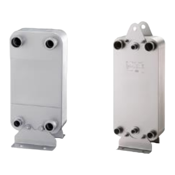
Brazed Plate heat Exchanger
S06-S07-S09
S22-S22H
S11-S12-S62-S71-S82
S16-S16H
S202
S222-S222H
S404-S424-S424H-S606
MODULES B + C2
TIS-PED-MI-15-03-002622-8383
TIS-PED-MI-16-11-275908-10461
0948 TUV ITALIA SRL
TÜV SÜD Gruppe
ONDA S.p.A.
IS079 rev .12 del 21/11/2016
Advanced Heat transfer Solutions

Advertisement

loading

Summary of Contents for Onda S06

  • Page 1: Declaration Of Conformity

    Onda S.p.A. Via Vittoria, 158 36065 Mussolente (VI) ITALY tel. +39 0444720720 ISTRUZIONI OPERATIVE OPERATING INSTRUCTIONS SCAMBIATORI A PIASTRE PLATE HEAT EXCHANGERS DECLARATION OF CONFORMITY In comply with the Annex VII of the European Directive 2014/68/EU We hereby declare that the pressure equipments detailed below have been...
  • Page 2 TIS-PED-MI-16-11-275908-10461 Notified Body: 0948 TUV ITALIA SRL TÜV SÜD Gruppe Responsible signature authorized established ONDA S.p.A. within the European Community : Manufacturer. Onda S.p.A. Via Vittoria, 158 36065 Mussolente (VI) ITALY IS079 rev .12 del 21/11/2016 Advanced Heat transfer Solutions...
  • Page 3 The Onda plate heat exchangers can be used to condense or evaporate coolants (gas/water exchangers) or used as single-phase heat exchangers (gas/gas). The following charts report the PED category pertaining to each type of exchanger, calculated at maxiumum allowed pressure for each model.
  • Page 4 Model P. max N° plates Model P. max N° plates 0-59 Art. 3.3 S06-S07-S09 51-100 0-40 Art. 3.3 0-20 Art. 3.3 S101 42.5 41-130 21-70 71-150 0-20 Art. 3.3 0-10 Art. 3.3 S182 42.5 21-110 11-30 111-130 31-150 0-20 0-30 Art.
  • Page 5: Handling And Transportation

    Before carrying out any operation on the exchanger, check the correspondence between the ordered machine and the received one. Please also verify that the model of the exchanger has been adequately sized with the ONDA selection programme for the type of application. 3.1 Enclosed documents These Operator Instructions are always enclosed with the exchanger.
  • Page 6: Installation

    A eyebolts in horizontal position B eyebolts in vertical position, lifting from horizontal to vertical position C eyebolts in vertical position, lifting from vertical position CAUTION: DO NOT HANDLE THE EXCHANGER WHEN IT IS UNDER PRESSURE 5. INSTALLATION 5.1 CONNECTIONS: In standard versions (one side with cooling circuit), the exchangers consist of 4 connections (F1, F2 e W1 W2) in the anterior part of the exchanger.
  • Page 7 On the side with the cooling connections, there are additional connections BW1 and BW2 which can be used for temperature probes. Depending on the type of application, the Onda plate connections may be of the following types: threaded internally (ISO-G), with flexible joint (Victaulic) or welded.
  • Page 8  For threaded attachment, avoid excessive tightening of the connections. Excessive force may ruin the brazing where the connection is placed.  For welded connections: - Wrap a wet cloth at the base of the connection where the welding is done - Use alloys containing an amount of silver over 40%.
  • Page 9 For standard exchangers, the cooling circuit includes attachments at the left of the plate (F1 and F2). The water circuit attachments are positioned on the right (W1 and W2) USE OF EVAPORATOR TYPE: Connect the cooling circuit and the water circuit as illustrated below: cooling entrance on the lower left side and water entrance on the upper right side.
  • Page 10 BRAZING-WELDING PROCEDURE Degrease and burnish the surfaces to be welded Insert the copper pipes into the connection, holding it in position and solder using a silver alloy of at least 45%. Do not direct the flame onto the exchanger. Use a wet cloth to prevent overheating of the exchanger. During welding of the exchanger, protect the interior of the circuit with a nitrogen flux to prevent oxidation.
  • Page 11 MAXIMUM DISTANCE 50 CM – MAXIMUM DISTANCE 30 CM USE OF CONDENSATOR TYPE: Connect the cooling circuit and water circuit as illustrated below: cooling entrance on the upper left side and water entrance on the lower right side for single-circuit exchangers. For double-circuit exchangers, the cooling entrance on the top and water entrance on the bottom, with exit on the opposite side.
  • Page 12 6. USE For correct functioning: DO NOT EXCEED THE MAXIMUM APPLICABLE LLIMITS IN TERMS OF PRESSURE (PS) AND (TS) SHOWN ON THE DATA TAG Use anti-freezing solitions in the case in which the evaporation point is close to the freezing point of the liquid, after verifying its compatibility with the construction materials of the exchanger.
  • Page 13 Make sure that the secondary fluid continues to flow inside the exchanger even after turning off the exchanger and while the pressure of the coolant is high enough to prevent freezing of the secondary fluid. When the machinery is started, the temperature corresponding to the pressure of the coolant inside the exchanger must not be lower than the freezing point of the secondary fluid.
  • Page 14: Warranty

    Therefore, during the warranty period, where any defects in the Products are objectively valid and recognized in writing by ONDA SpA, the latter will provide free repair or, at its discretion, the replacement of defective Products, with delivery ex works (Ex Works - Incoterms 2000).
  • Page 15 S.p.A., the replacement of the Products or their possible adaptation to the new regulations shall be excluded. However, Onda S.p.A shall not be liable for the use of Products in non-compliance with Italian and/or foreign laws and/or regulations that came into force after the sending date of the relevant order confirmation by ONDA S.p.A.
  • Page 16 ONDA BPHE can be used to condensate or evaporate refrigerant fluids ( refrigerant/ water BPHE) or as single-phase heat exchangers (refrigerant/refrigerant BPHE). In the tables below, according to 97/23/EC, there is the highest applicable category for each model at the maximum allowable pressure.
  • Page 17 Scambiatori Gas Gr. II - Liquido Gr. II Model P. max N° plates Model P. max N° plates 0-59 Art. 3.3 S06-S07-S09 51-100 0-40 Art. 3.3 0-20 Art. 3.3 S101 42.5 41-130 21-70 71-150 0-20 Art. 3.3 0-10 Art. 3.3 S182 42.5...