Advertisement
Available languages
Available languages
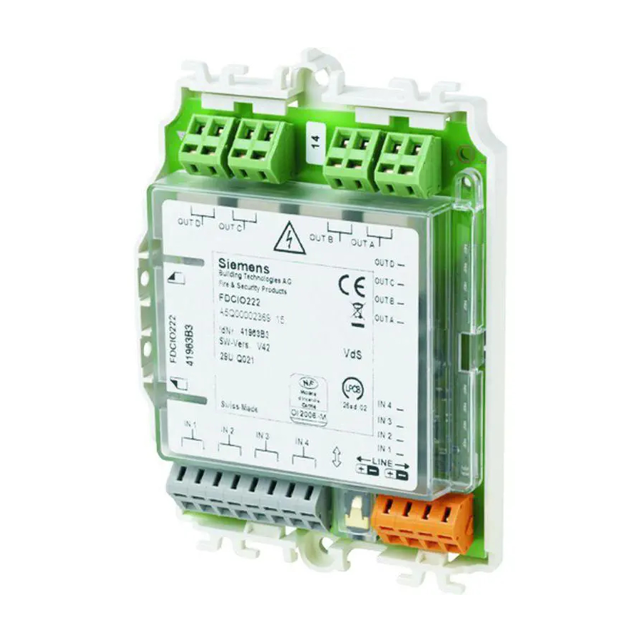
FDCIO222, FDCIO224
en
Input/output module
de
Ein-/Ausgabebaustein
fr
Interface d'entrées/sorties
es
Módulo de entrada/salida
it
Modulo in/out digitali
en
de
Montage
fr
Montage
es
Montaje
it
Montaggio
Fig. 3
FDCIO222
IN
+
IN1
IN1
IN2
IN2
IN3
IN3
IN4
IN4
LINE +
LINE –
LINE +
LINE –
008176
Rs 1k15
Rp 3k01
Fig. 6
OUT D
OUT D
OUT C
OUT C
OUT B
OUT B
OUT A
OUT A
Fig. 8
FDCH221
Housing
Gehäuse
Boîtier
Carcasa
Contenitore
Fig. 1
Fig. 4
FDCIO224
IN
1
560
+
2k7
3k3
Fig. 7
Fig. 9
Building Technologies
Fire Safety & Security Products
Fig. 2
Fig. 5
2
680
Advertisement
Table of Contents

Related Manuals for Siemens FDCIO222


Summary of Contents for Siemens FDCIO222
- Page 1 FDCIO222, FDCIO224 FDCH221 Input/output module Housing Ein-/Ausgabebaustein Gehäuse Interface d'entrées/sorties Boîtier Módulo de entrada/salida Carcasa Modulo in/out digitali Contenitore Installation Montage Montage Montaje Montaggio Fig. 1 Fig. 2 Fig. 3 Fig. 4 Fig. 5 FDCIO224 FDCIO222 Rs 1k15 Rp 3k01 Fig.
- Page 2 Installation 5. Use two M3 x 12 screws to fit the module in the housing Intended use (Fig. 2). 6. Close housing using supplied screws (Fig. 5). The input/output module can use the outputs for control purposes and the inputs to monitor the statuses of Install input/output module on a top hat rail potential-free contacts.
- Page 3 Montage 5. Montieren Sie den Baustein mit zwei Schrauben Verwendungszweck M3 x 12 im Gehäuse (Fig. 2). 6. Schließen Sie das Gehäuse mit den mitgelieferten Der Ein-/Ausgabebaustein kann mit den Ausgängen Schrauben (Fig. 5). Steuerungen vornehmen und mit den Eingängen Zu- Ein-/Ausgabebaustein auf eine Hutschiene montieren stände von potenzialfreien Kontakten überwachen.
- Page 4 Montage 5. Montez le module dans le boîtier avec deux vis Application M3 x 12 (fig. 2). 6. Fermez le boîtier avec les deux vis fournies lors de la L'interface d'entrées/sorties peut exécuter des livraison (fig. 5). commandes avec les sorties et surveiller les états de Monter une interface d'entrées/sorties sur un profilé...
- Page 5 Montaje 5. Monte el módulo con dos tornillos M3 x 12 en la Uso previsto carcasa (Fig. 2). 6. Cierre la carcasa con los tornillos suministrados Con las salidas, el módulo de entrada/salida puede (Fig. 5). realizar funciones de control y con las entradas, Montar el módulo de entrada/salida en un carril DIN monitorizar los estados de contactos sin potencial.
- Page 6 Montaggio 5. Montare il separatore di linea multiplo nel contenitore Destinazione d'uso (Fig. 2) con due viti M3 x 12. 6. Fissare il contenitore con le viti fornite in dotazione Il modulo in/out digitali può adempiere a funzioni di (Fig. 5). comando mediante le uscite e può...
- Page 7 Bestell- Détails pour passer Datos de Dati per Details for ordering angaben commande pedido l'ordinazione FDCIO222 A5Q00002369 Input/Output module Ein-/Ausgabebaustein Interface d'entrées / sorties Módulo de entrada/salida Modulo in/out digitali FDCIO224 A5Q00018689 Input/Output module Ein-/Ausgabebaustein Interface d'entrées / sorties Módulo de entrada/salida...
- Page 8 Bornier 1 … 2,5 mm Terminal de conexión 1 … 2,5 mm Morsetto di collegamento 1 … 2,5 mm Siemens Switzerland Ltd © Siemens Switzerland Ltd 2007-2009 Industry Sector Data and design subject to change without notice. Building Technologies Division...
Need help?
Do you have a question about the FDCIO222 and is the answer not in the manual?
Questions and answers