Table of Contents
Advertisement
Available languages
Available languages
Quick Links
FDCI361
en
Input module
de
Eingabebaustein
fr
Interface d'entrées
es
Módulo de entrada
it
Modulo ingressi digitali
en
Installation
de
Montage
fr
Montage
es
Montaje
it
Montaggio
Fig. 1
FDCI361
FDCIO361
A6V11712824_----_a
2020-04-29
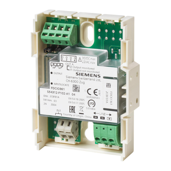
FDCIO361
Input/Output module
Ein-/Ausgabebaustein
Interface d'entrées / sorties
Módulo de entrada/salida
Modulo in/out digitali
Fig. 4
3.3 kW
Fig. 7
FDCH221
Housing
Gehäuse
Boîtier
Carcasa
Contenitore
Fig. 2
Fig. 5
FDCI361
FDCIO361
Fig. 3
Fig. 6
680 W
3.3 kW
Fig. 8
Smart Infrastructure
Advertisement
Table of Contents

Subscribe to Our Youtube Channel
Related Manuals for Siemens FDCI361


Summary of Contents for Siemens FDCI361
- Page 1 FDCI361 FDCIO361 FDCH221 Input module Input/Output module Housing Eingabebaustein Ein-/Ausgabebaustein Gehäuse Interface d'entrées Interface d'entrées / sorties Boîtier Módulo de entrada Módulo de entrada/salida Carcasa Modulo ingressi digitali Modulo in/out digitali Contenitore Installation Montage Montage Montaje Montaggio Fig. 2 Fig. 3 Fig.
- Page 2 3.3 k W 2 AT 2 AT DC 24 V external DC 24 V external Fig. 9 Fig. 10 Max. DC 30 V Max. AC 22 V FDCIO361 FDCI361 FDCI361 2 AT NO/NC FDCIO361 FDCIO361 not used LINE – not used Fig.
- Page 3 Installation Intended use Electric connection The module can use the output for control purposes and NOTICE the input to monitor the status of a potential-free contact. Incorrect polarity and reliability of contact A housing is available to protect the module from environmental influences and to raise the protection Module defect or line interrupt category.
- Page 4 Montage 4. Befestigen Sie die Kabelverschraubungen M20 am Verwendungszweck Gehäuse und führen Sie die Kabel ein (Fig. 5). Der Baustein kann mit dem Ausgang eine Steuerung 5. Montieren Sie den Baustein mit zwei Schrauben vornehmen und mit dem Eingang den Zustand eines M3 x 12 im Gehäuse (Fig.
- Page 5 Montage 4. Fixez les presse-étoupe M20 sur le boîtier et introduisez Application les câbles (Fig. 5). Le module d'interface peut effectuer des fonctions de 5. Montez le module d'interface dans le boîtier avec deux commande par l'intermédiaire de la sortie et surveiller vis M3 x 12 (Fig.3).
- Page 6 Montaje 4. Sujete los prensaestopas para cable M20 en la carcasa Uso previsto e introduzca los cables (Fig. 5). Con la salida, el módulo puede realizar un control y con la 5. Monte el módulo con dos tornillos M3 x 12 en la entrada, monitorizar el estado de un contacto sin carcasa (Fig.
- Page 7 Montaggio 3. Montare il contenitore con due viti su una superficie Destinazione d'uso piana (Fig. 4). Il modulo può effettuare un comando con l'uscita e 4. Fissare i pressatavi M20 al contenitore e introdurre i sorvegliare lo stato di un contatto a potenziale zero con cavi (Fig.
- Page 8 Siemens Switzerland Ltd Smart Infrastructure Global Headquarters Theilerstrasse 1a CH-6300 Zug Tel. +41 58 – 724 24 24 © Siemens Switzerland Ltd, 2020 www.siemens.com/buildingtechnologies Technical specifications and availability subject to change without notice. A6V11712824_----_a SAP order no. A5Q00080060 Fire Safety...
Need help?
Do you have a question about the FDCI361 and is the answer not in the manual?
Questions and answers