Advertisement
Quick Links
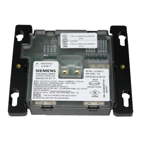
Model FDCIO422
Addressable Input/Output module
Installation Instructions
INTRODUCTION
The FDCIO422 is used for the connection of up
to 2 independent Class A or 4 independent
Class B dry N/O configurable contacts. Input
lines can be supervised for open, short and
ground fault conditions (depending on EOL
termination resistor and class configuration).
Inputs can be independently configured via the
fire control panel for alarm, trouble, status or
supervisory zones.
The FDCIO422 has 4 programmable outputs
with 4 potential-free latching type form A relay
contacts for fire control installations.
Status indication per LED for each input and
output plus 1 LED for general status of the
device. Power supply via FDnet (supervised
power limited).
· Including 4 EOL devices (470 Ω)
· 3 separators to separate the power limited
wiring from the non-power limited.
Separators are delivered in 3 different sizes
11
for standard 4
/
16
extension ring and 5-inch box (RANDL).
Figure 2 Removing the cage and the terminal strips from the carrier
A6V10324662_g_en_US
2016-01-20
11
-inch box, 4
/
-inch
16
Download link Desigo:
https://www.buildingtechnologies.siemens.com/extranet/ba-sp/
Download link Cerberus PRO:
http://iknow.us009.siemens.net/infolink
Figure 1 FDCIO422 cage and carrier
CAUTION
This device is not intended for
applications in explosive environments.
Class A is equivalent to DCLA (Canada)
Class B is equivalent to DCLB (Canada)
For complete configuration and
commissioning of the FDCIO422 also refer
to the user documentation of your panel,
especially for the software tool used for
configuration.
SIEMENS Industry, Inc.
S54322-F4-A1
CAUTION
Electric shock!
High voltages may
occur on the terminals.
Always use a faceplate
and the separator(s).
Building Technologies Division
Advertisement

Related Manuals for Siemens FDCIO422


Summary of Contents for Siemens FDCIO422
- Page 1 Download link Cerberus PRO: http://iknow.us009.siemens.net/infolink INTRODUCTION The FDCIO422 is used for the connection of up to 2 independent Class A or 4 independent Class B dry N/O configurable contacts. Input CAUTION lines can be supervised for open, short and...
-
Page 2: Programming Instructions
3). Follow the instructions in the DPU manual or 8720 manual to program the FDCIO422 to the desired address. Record the device address on the label located on the front of the module. The FDCIO422 can now be installed and wired to the system. - Page 3 ¼ inch from all of the or non-power limited fire protection signaling following items located within an outlet box: conductors. For the FDCIO422, wiring to the · Electric light terminal block for line and inputs must enter the ·...
-
Page 4: Technical Data
2 screws provided with the FDCIO422. WARNING It is not allowed to use the module without Be sure to program the FDCIO422 before the faceplate. Remove the faceplate for fastening the faceplate to the unit. service and maintenance reasons only! -
Page 5: Wiring Notes
8. The inputs must be wired potential-free. 18. Positive and negative ground fault detected at 9. FDCIO422 is polarity insensitive. Line -6 and Line -5 <25 kΩ for inputs 1 – 4. can be either line of the loop. - Page 6 The configuration of the input must error on the communication line (open line to correspond to the actual wiring. the control panel, FDCIO422 power failure). An EOL must be mounted to the input in case of this The following configurations are possible for input is NOT used.
- Page 7 OUT B OUT C OUT D Figure 10 FDCIO422 input wiring Class A and Class B (for details of Line 1 and 2 wiring see Figure 8, for details of the input wiring see Figure 11.) Siemens Industry, Inc. A6V10324662_g_en_US...
- Page 8 ① CAUTION: FOR SYSTEM SUPERVISION – FOR TERMINALS IDENTIFIED WITH A ① DO NOT USE LOOPED WIRE TERMINALS. BREAK WIRE RUN TO PROVIDE SUPERVISION OF CONNECTIONS. ② Use Siemens TB-EOL terminal P/N S54322-F4-A2 or equivalent. ③ Use only normally open dry contact SWITCHES for the inputs Figure 11 Wiring end of line and switch ·...
Need help?
Do you have a question about the FDCIO422 and is the answer not in the manual?
Questions and answers