Sign In
Upload
Download
Table of Contents
Contents
Add to my manuals
Delete from my manuals
Share
URL of this page:
HTML Link:
Bookmark this page
Add
Manual will be automatically added to "My Manuals"
Print this page
×
Bookmark added
×
Added to my manuals
Manuals
Brands
D-Link Manuals
Switch
DGS-1210-10
Manual
D-Link DGS-1210-10 Manual
Smart managed
Hide thumbs
Also See for DGS-1210-10
:
Reference manual
(113 pages)
1
Table Of Contents
2
3
4
5
6
7
8
9
10
11
12
13
14
15
16
17
18
19
20
21
22
23
24
25
26
27
28
29
30
31
32
33
34
35
36
37
38
39
40
41
42
43
44
45
46
47
48
49
50
51
52
53
54
55
56
57
58
59
60
61
62
63
64
65
66
67
68
69
70
71
72
73
74
75
76
77
78
79
80
81
82
83
84
85
86
87
88
89
90
91
92
93
94
95
96
97
98
99
100
101
102
103
104
105
106
107
108
109
110
111
112
113
114
115
116
117
118
119
120
121
122
123
124
125
126
127
128
129
130
131
132
133
134
135
136
137
138
139
140
141
142
143
144
145
146
147
148
149
150
151
152
153
154
155
156
157
158
159
160
161
162
163
164
165
166
167
168
169
170
171
page
of
171
Go
/
171
Contents
Table of Contents
Bookmarks
Table of Contents
Table of Contents
About this Guide
Terms/Usage
Copyright and Trademarks
1 Product Introduction
Dgs-1210-10
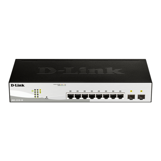
Front Panel
Rear Panel
Dgs-1210-10P
Front Panel
Rear Panel
Dgs-1210-10Mp
Front Panel
Rear Panel
Dgs-1210-20
Front Panel
Rear Panel
Dgs-1210-26
Front Panel
Rear Panel
Dgs-1210-28
Front Panel
Dgs-1210-28P
Front Panel
Rear Panel
Dgs-1210-28Mp
Front Panel
Rear Panel
Dgs-1210-52
Front Panel
Rear Panel
Dgs-1210-52Mp
Front Panel
Rear Panel
LED Indicators
2 Hardware Installation
Safety Cautions
Step 1: Unpacking
Step 2: Switch Installation
Desktop or Shelf Installation
Rack Installation
Step 3: Plugging in the AC Power Cord with Power Cord Clip
Power Failure
Grounding the Switch
3 Getting Started
Management Options
Using Web-Based Management
Supported Web Browsers
Connecting to the Switch
Login Web-Based Management
Smart Wizard
Web-Based Management
4 Web-Based Switch Configuration
Smart Wizard Configuration
Step 1 - Web Mode
Step 2 - IP Information
Step 3 - Password
Step 4 - SNMP (Only for Standard Mode)
Web-Based Management
Tool Bar > Save Menu
Save Configuration
Save Log
Tool Bar > Tools Menu
Reset
Reset System
Reboot Device
Configuration Backup and Restore
Firmware Backup and Upgrade
Flash Information
Tool Bar > Wizard
Tool Bar > Online Help
Tool Bar > Surveillance Mode
Function Tree
Device Information
System > System Settings
System > Password
System > Port Settings
System > Port Description
System > DHCP Auto Configuration
System > DHCP Relay > DHCP Relay Global Settings
System > DHCP Relay > DHCP Relay Interface Settings
System > DHCP Local Relay Settings
System > Dhcpv6 Relay Settings
System > System Log Configuration > System Log Settings
System > System Log Configuration > Syslog Host
System > Time Profile
System > Power Saving
System > Ieee802.3Az EEE Settings
System > D-Link Discover Protocol Settings
System > Firmware Information
Vlan > 802.1Q Vlan
Vlan > 802.1Q Vlan Pvid
VLAN > Voice VLAN > Voice VLAN Global Settings
VLAN > Voice VLAN > Voice VLAN Port Settings
VLAN > Voice VLAN > Voice Device List
VLAN > Auto Surveillance VLAN > Auto Surveillance Properties
VLAN > Auto Surveillance VLAN > MAC Settings and Surveillance Device
VLAN > Auto Surveillance VLAN > ONVIF IPC Information
VLAN > Auto Surveillance VLAN > ONVIF NVR Information
L2 Functions > Jumbo Frame
L2 Functions > Port Mirroring
L2 Functions > Loopback Detection
L2 Functions > MAC Address Table > Static MAC
L2 Functions > MAC Address Table > Dynamic Forwarding Table
L2 Functions > Spanning Tree > STP Bridge Global Settings
L2 Functions > Spanning Tree > STP Port Settings
L2 Functions > Spanning Tree > MST Configuration Identification
L2 Functions > Spanning Tree > STP Instance Settings
L2 Functions > Spanning Tree > MSTP Port Information
L2 Functions > Link Aggregation > Port Trunking
L2 Functions > Link Aggregation > LACP Port Settings
L2 Functions > Multicast > IGMP Snooping
L2 Functions > Multicast > MLD Snooping
L2 Functions > Multicast > Multicast Forwarding
L2 Functions > Multicast > Multicast Filtering Mode
L2 Functions > SNTP > Time Settings
L2 Functions > SNTP > Timezone Settings
L2 Functions > LLDP > LLDP Global Settings
L2 Functions > LLDP > LLDP-MED Settings
L2 Functions > LLDP > LLDP Port Settings
L2 Functions > LLDP > 802.1 Extension TLV
L2 Functions > LLDP > 802.3 Extension TLV
L2 Functions > LLDP > LLDP Management Address Settings
L2 Functions > LLDP > LLDP Management Address Table
L2 Functions > LLDP > LLDP Local Port Table
L2 Functions > LLDP > LLDP Remote Port Table
L2 Functions > LLDP > LLDP Statistics
L3 Functions > IP Interface
L3 Functions > Ipv6 Neighbor Settings
L3 Functions > Ipv4 Static Route
L3 Functions > Ipv4 Routing Table Finder
L3 Functions > Ipv6 Static Route
L3 Functions > Ipv6 Routing Table Finder
L3 Functions > ARP > ARP Table Global Settings
L3 Functions > ARP > Static ARP Settings
Qos > Bandwidth Control
Qos > 802.1P/Dscp/Tos
Security > Trusted Host
Security > Port Security
Security > Traffic Segmentation
Security > Safeguard Engine
Security > Storm Control
Security > ARP Spoofing Prevention
Security > DHCP Server Screening
Security > SSL
Security > Dos Prevention Settings
Security > SSH > SSH Settings
Security > SSH > SSH Authmode and Algorithm Settings
Security > SSH > SSH User Authentication Lists
Security > Smart Binding > Smart Binding Settings
Security > Smart Binding > Smart Binding
Security > Smart Binding > White List
Security > Smart Binding > Black List
AAA > RADIUS Server
AAA > 802.1X > 802.1X Global Settings
AAA > 802.1X > 802.1X Port Settings
AAA > 802.1X > 802.1X User
ACL > ACL Wizard
ACL > ACL Access List
ACL > ACL Access Group
ACL > ACL Hardware Resource Status
Poe > Poe Global Settings (Only for DGS-1210-10P/10MP/28P/28MP/52MP)
Poe > Poe Port Settings (Only for DGS-1210-10P/10MP/28P/28MP/52MP)
SNMP > SNMP > SNMP Global Settings
SNMP > SNMP > SNMP User
SNMP > SNMP > SNMP Group Table
SNMP > SNMP > SNMP View
SNMP > SNMP > SNMP Community
SNMP > SNMP > SNMP Host
SNMP > SNMP > SNMP Engine ID
SNMP > RMON > RMON Global Settings
SNMP > RMON > RMON Statistics
SNMP > RMON > RMON History
SNMP > RMON > RMON Alarm
SNMP > RMON > RMON Event
Monitoring > Port Statistics
Monitoring > Cable Diagnostics
Monitoring > System Log
5 Surveillance Mode Configuration
Web User Interface
Surveillance Overview
Surveillance Topology
Device Information
Port Information
IP-Camera Information
NVR Information
Poe Information
Poe Scheduling
Time > Clock Settings
Time > SNTP Settings
Surveillance Settings
Surveillance Log
Health Diagnostic
Tool Bar > Wizard
Tool Bar > Tools Menu
Reset System
Reboot Device
Configuration Backup & Restore
Firmware Backup and Upgrade
Firmware Information
Flash Information
Tool Bar > Save
Tool Bar > Help
Tool Bar > Online Help
Tool Bar > Standard Mode
6 Command Line Interface
To Connect a Switch Via TELNET
Logging on to the Command Line Interface
CLI Commands
Download
Upload
Config Firmware Image_Id
Config Ipif System
Config Ipif System
Logout
Ping
Ping6
Reboot
Reset Config
Show Boot_File
Show Firmware Information
Show Flash Information
Show Ipif
Show Switch
Show Route
Config Account Admin Password
Save
Debug Info
Appendix A - Ethernet Technology
Gigabit Ethernet Technology
Fast Ethernet Technology
Switching Technology
Appendix B - Technical Specifications
Hardware Specifications
Features
L2 Features
L3 Features
Vlan
Qos (Quality of Service)
Security
Oam
Management
D-Link Green Technology
Appendix C - Rack Mount Instructions
Regulatory Information
Federal Communication Commission Interference Statement
Japan Voluntary Control Council for Interference Statement
警告使用者
CE EMI Class a Warning
Safety Instructions
Sicherheitsvorschriften
Consignes de Sécurité
Instrucciones de Seguridad
Istruzioni Per la Sicurezza
Veiligheidsinformatie
Disposing of and Recycling Your Product
Advertisement
Quick Links
1
Using Web-Based Management
2
Management Options
Download this manual
See also:
Reference Manual
Table of
Contents
Previous
Page
Next
Page
1
2
3
4
5
Advertisement
Table of Contents
Need help?
Do you have a question about the DGS-1210-10 and is the answer not in the manual?
Ask a question
Questions and answers
Related Manuals for D-Link DGS-1210-10
Switch D-Link DGS-1210-10 Reference Manual
Dgs-1210 series web smart switch (113 pages)
Switch D-Link Web Smart Switch DGS-1210-16 Reference Manual
Web ui reference guide web smart switch series (109 pages)
Switch D-Link DGS-1210-10P Reference Manual
Web smart switch web ui reference guide (109 pages)
Smart switch D-Link DGS-1210-20 Reference Manual
(108 pages)
Switch D-Link DGS-1210-28 Reference Manual
Web smart switch (102 pages)
Switch D-Link DGS-1210-10P User Manual
Web smart switch (73 pages)
Switch D-Link DGS-1210-48/E Getting Started Manual
Web smart switch (49 pages)
Network Router D-Link DGS-1210-28P Getting Started Manual
Web smart switch (49 pages)
Switch D-Link DGS-1210-52MP Quick Installation Manual
(15 pages)
Wireless Router D-Link DGS-1210-28P Manual
(15 pages)
Switch D-Link DGS-1210-52MP Quick Installation Manual
(13 pages)
Switch D-Link DGS 1210-28P Manual
Pro dsx - hdmi over ip network switch configuration (9 pages)
Network Hardware D-Link DES-1210-28P Selection Manual
Product selection guide for d-link business surveillance solutions (6 pages)
Switch D-link DGS-1210-10P Specifications
Web smart 10/16/24/48-port gigabit switches (5 pages)
Switch D-Link DGS-1210 Series User Manual
Metro ethernet managed switch (12 pages)
Switch D-Link DGS-1210-10/FL Quick Installation Manual
8 10/100/1000base-t + 2 1000base-x sfp ports l2 management switch (15 pages)
This manual is also suitable for:
Dgs-1210-10mp
Dgs-1210-10p
Dgs-1210-26
Dgs-1210-28
Dgs-1210-28p
Dgs-1210-28mp
...
Show all
Dgs-1210-52
Dgs-1210-52mp
Dgs-1210-20
Table of Contents
Save PDF
Print
Rename the bookmark
Delete bookmark?
Delete from my manuals?
Login
Sign In
OR
Sign in with Facebook
Sign in with Google
Upload manual
Upload from disk
Upload from URL


Need help?
Do you have a question about the DGS-1210-10 and is the answer not in the manual?
Questions and answers