Table of Contents
Advertisement
Advertisement
Table of Contents

Related Manuals for Carestream CS 3500


Summary of Contents for Carestream CS 3500
- Page 1 User and Installation Guide...
- Page 2 The information in this document is subject to change. Neither Carestream Health, Inc. nor any of its subsidiaries shall be liable for errors contained herein or for incidental damages in conjunction with the furnishing, performance, or use of this material.
-
Page 3: Table Of Contents
This Guide Chapter 2 CS 3500 Overview ..... . . 3 CS 3500 Overview CS 3500 Holders Overview ....5 CS 3500 USB Cable Storage . - Page 4 Removing Soft-Tissue Artifacts ....29 Preparing the CS 3500 ....30 Using the Collar to Scan Anterior Teeth .
-
Page 5: Conventions In This Guide
CAUTION: Alerts you to a condition that might cause serious damage. Important: Alerts you to a condition that might cause problems. Note: Emphasizes important information. Tip: Provides extra information and hints. CS 3500 User and Installation Guide (9H4853)_Ed07... -
Page 6: Conventions In
Chapter 1 Conventions in This Guide... -
Page 7: Cs 3500 Overview
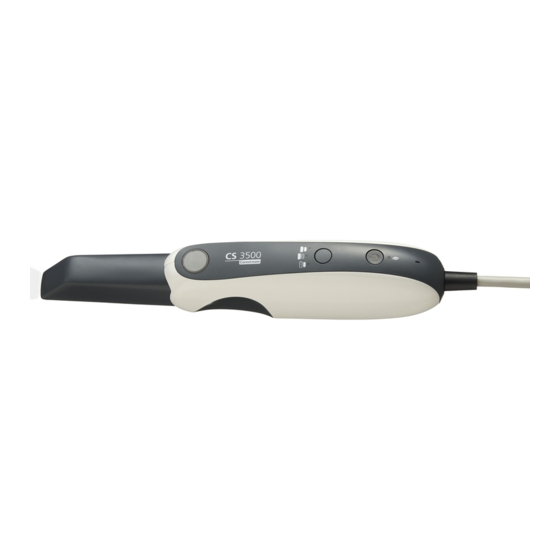
CS 3500 Overview The CS 3500 is designed to acquire 3D still images in the following modes: • Lower jaw • Upper jaw • Buccal bite registration CS 3500 Overview Figure 1 CS 3500 Components Overview 1 Reusable tip The tip can be installed facing upward or downward. Tips come in two sizes: regular and small. - Page 8 If the indicators are blinking rapidly and the Overheating icon is displayed on the Acquisition interface, place the CS 3500 in the holder for 5 to 10 minutes. The CS 3500 will become inactive and cool down. 4 Mode button Press the button to switch between different modes.
-
Page 9: Cs 3500 Holders Overview
CS 3500 Holders Overview The CS 3500 has both a desktop and a wall mount holder. Place the CS 3500 in the holder when you are not using it. Figure 2 CS 3500 and Desktop Holder Figure 3 CS 3500 and Wall Mount Holder Note: The CS 3500 goes into inactive mode when inserted into the holder. -
Page 10: Cs 3500 Usb Cable Storage
CS 3500. Figure 4 Correct CS 3500 Cable Storage Do not wrap the cable around the handle of the CS 3500 or create any sharp bends in the cable. Figure 5 Incorrect CS 3500 Cable Storage... -
Page 11: Minimum Computer System Requirements
CS 3500 Software Overview Minimum Computer System Requirements For the minimum computer system requirements, see the CS 3500 Safety, Regulatory, and Technical Specifications User Guide. Important: It is MANDATORY to check that your computer system configuration is compatible with the computer system requirements for the CS 3500 software. -
Page 12: Cs 3500 Acquisition Interface Overview
CS 3500 Acquisition Interface Overview The CS 3500 Acquisition interface enables you to acquire images in two ways: • Partial arch scan: Several teeth in the preparation area on both the upper and lower jaws, and a buccal bite registration. -
Page 13: Toolbar Overview
True Color button: Displays the 3D model in the actual color of the patient’s hard and soft tissues. Freeze button: Prevents the 3D model from being resized and rotated. Zoom Fit button: Scales the 3D model to the best size to fit the display region. CS 3500 User and Installation Guide (9H4853)_Ed07... - Page 14 Reset button: Reverses all deletions and returns to the initial acquisition. Next button: Moves to the next step in the acquisition workflow. Back button: Moves to the previous step in the acquisition workflow. 10 Chapter 3 CS 3500 Software Overview...
- Page 15 No Tip icon: Indicates the CS 3500 does not have a tip Overheating icon: Indicates the CS 3500 is overheating. If this icon is displayed, place the CS 3500 in the holder for 5 to 10 minutes. The CS 3500 will become inactive and cool down.
-
Page 16: Select Acquisition Type Window
Use the import feature to access an acquisition you have previously saved. Note: The acquisition type or folder path you select is selected by default the next time you open the Acquisition interface. 12 Chapter 3 CS 3500 Software Overview... -
Page 17: Preparation Check
Upper: Click the Upper Jaw button to view or hide the upper jaw. Lower: Click the Lower Jaw button to view or hide the lower jaw. CS 3500 User and Installation Guide (9H4853)_Ed07... -
Page 18: Preferences Dialog Boxes Overview
With Scan Body: Click the With Scan Body button to view the jaw with the scan body. Preferences Dialog Boxes Overview The Preferences dialog boxes enable you to select the CS 3500 Acquisition interface settings. It is recommended that you set up your preferences before using the CS 3500. General Preferences... -
Page 19: Scanner Preferences
• Fast Capture: Select to enable the fastest capture speed. Fast capture is recommended for experienced users who are familiar with using the CS 3500 and maintaining a 30% overlap with each image. Note: When Fast Capture is selected, the guidance systems are disabled. - Page 20 Enable Image Review: Select to display color images immediately after an acquisition. Note: When Enable Image Review is selected, acquisition speed is reduced. • Default Acquisition Mode: Select the jaw you will always scan first. 16 Chapter 3 CS 3500 Software Overview...
-
Page 21: Tools Preferences
Create Support File: Click to select the folder where the log files for service information are saved. • Diagnose Scanner: After attaching the service calibration diagnostic tip, click to run a diagnostic test to verify the accuracy of the CS 3500. See “Testing Image Quality and Accuracy” on page 21 for more information. - Page 22 18 Chapter 3 CS 3500 Software Overview...
-
Page 23: Setting Up The Cs 3500
CS 3500 flash drive in Windows Explorer and double-click wizard.exe. Select Run wizard.exe. The Autorun window is displayed. Select a language from the drop-down list, select CS 3500, and click Run Installation. The Installation Wizard window is displayed. Follow the on-screen instructions to complete the installation. - Page 24 Insert the DC power supply (A) into the jack on the USB plug (B), and insert the power adapter (C) into an outlet. Connect the USB cable to the computer. Press the power button one second to power on the CS 3500. Ensure the power indicator turns orange. Wait until the USB connection indicator turns blue.
-
Page 25: Testing Image Quality And Accuracy
Testing Image Quality and Accuracy After setting up the CS 3500, you should verify the accuracy of the CS 3500, using the service calibration diagnostic tip. We recommend that you run this test once per month. In addition, you should verify the accuracy of the CS 3500: •... -
Page 26: Installing The Cs 3500 Desktop Holder
Attach the adhesive tape to the indentations in the holder (A). Remove the adhesive tape protection (B). Place the taped side of the CS 3500 holder on the clean surface (C) and press firmly several times for correct adherence. The maximum adherence is obtained after two hours. -
Page 27: Installing The Cs 3500 Wall Mount Holder
Insert screws through the appropriate holes in the holder to affix it to a solid surface. Important: If the holder is not properly installed, there is a risk that the holder can fall off the wall, resulting in damage to the CS 3500. CS 3500 User and Installation Guide (9H4853)_Ed07... - Page 28 24 Chapter 4 Setting Up the CS 3500...
-
Page 29: Using The Imaging Software
Accessing the Acquisition Interface You can access the CS 3500 Acquisition interface from inside the CS Imaging software, the CS Orthodontic Imaging software, the CS OMS Imaging software, or from inside your practice management software. -
Page 30: Setting Up Preferences
Setting Up Preferences Set up your preferences before using the CS 3500. To set up the preferences, follow these steps: On the Acquisition interface, click . The Preferences dialog box is displayed. Click to set the general preferences. Click to set the CS 3500 preferences. -
Page 31: Cs 3500 Tools And Tips
Projection Light: When the guidance system is enabled with Feedback selected, a light is emitted from the tip of the CS 3500 to indicate if the acquisition is correct. The light is green if the image is scanned correctly and orange if the image is not scanned correctly. -
Page 32: Important Scanning Procedures-Restoration Acquisition
Important Scanning Procedures—Restoration Acquisition Scanning One Surface at a Time • Start with the occlusal surface, beginning with the preparation area and then scanning the surrounding teeth on the jaw. • Next, scan the lingual surface, starting with the preparation area and then scanning the surrounding teeth on the jaw. -
Page 33: Important Scanning Procedures-Implant Acquisition
If you detect soft-tissue artifacts in an image during acquisition, click and left-click at several points around the soft tissue to draw lines around it. Double-click to delete the soft tissue. Re-scan the area to fill any holes. CS 3500 User and Installation Guide (9H4853)_Ed07... -
Page 34: Preparing The Cs 3500
To prepare the CS 3500, follow these steps: Make sure the lens window at the base of the CS 3500 is clean by wiping it with a moist, lint-free cloth or lens tissue. Slide the tip onto the CS 3500 as illustrated, with the lens facing downward (A) for a lower jaw view or upward (B) for an upper jaw view. -
Page 35: Using The Collar To Scan Anterior Teeth
Press the power button for one second to power on the CS 3500. 1 sec. Let the CS 3500 warm up for approximately three minutes to enable the antifog feature on the tip. Using the Collar to Scan Anterior Teeth It is recommended that you use the collar when scanning the anterior teeth. - Page 36 32 Chapter 5 Getting Started...
-
Page 37: Scanning Teeth On The Upper And Lower Jaw
Acquiring a 3D Model for Restoration You can use the CS 3500 to scan either a partial or full arch. For either type of scan, you should acquire images of the upper jaw, lower jaw, and the buccal bite registration. The software combines these images to create a 3D model. - Page 38 On the CS 3500, press the mode button for one second to select the acquisition mode. The mode indicator LED turns green. Note: Upper jaw is the default setting until you change it. For information on how to change the default setting, see “Scanner Preferences”...
- Page 39 Important: When scanning a tooth, keep approximately a 30% overlap with the last image. Slowly move the CS 3500 tip along the occlusal surface to scan the remaining teeth in the preparation area, keeping approximately a 30% overlap with the last image.
- Page 40 The example below shows a 3D model of the upper jaw when the occlusal, lingual, and buccal surfaces have been completely scanned. Important: If holes are displayed in the scanned image on the preparation area, re-scan the area until the holes are filled. Use the mouse wheel to zoom in on the preparation area for a closer look.
-
Page 41: Scanning The Buccal Bite Registration
Have the patient bite down. Position the CS 3500 at a 90-degree angle to the buccal surface of the preparation area, and align the point where the upper and lower teeth meet in the middle of the video preview screen. - Page 42 To complete a partial buccal bite image, move the CS 3500 slightly more gingival, toward the missing arch, and ensure that there is at least a 30% overlap between the second buccal bite acquisition and the previous one.
-
Page 43: Preparation Selection
Place the cursor over the area you want to refine, and left-click and drag the mouse to select the teeth for refinement. You should include the preparation, the adjacent surfaces of neighboring teeth, the teeth on the opposite arch, and at least one buccal bite registration acquisition in this selection. CS 3500 User and Installation Guide (9H4853)_Ed07... - Page 44 Important: Use the mouse to angle the image, and select teeth from above -- not from the side. This prevents teeth behind the target teeth from being refined. Important: You cannot select more than half an arch, or you will not be able to continue with the refinement process.
-
Page 45: Check
If you find holes in the preparation area, click and re-scan the teeth that are missing data. Repeat steps 1 through 3 until you are satisfied with the 3D model. CS 3500 User and Installation Guide (9H4853)_Ed07... - Page 46 Click . The arch diagram is displayed. Click the Adult or Child icon to display the appropriate arch. Select the teeth on the arch that were acquired for the 3D model, including those on the upper and lower jaw. If you are exporting the 3D model to a dental lab, you can draw a margin line reference on the 3D model.
- Page 47 For instructions on using the mesh viewer, click the ? button in the CS Mesh Viewer interface. If you are sending the DCM file to a lab, ask the lab to download the CS Mesh Viewer from the following link: http://sas-origin.onstreammedia.com/origin/carestreamhealthinc/CSMeshView er/CSMeshViewer.zip CS 3500 User and Installation Guide (9H4853)_Ed07...
-
Page 48: Drawing Margin Lines
Drawing Margin Lines If you are exporting the 3D model to a dental lab, you can have the software automatically draw a margin line on the 3D model, or you can manually draw the margin line. Important: The Auto Margin Line feature can be used only with crowns. - Page 49 • To delete the margin line, select the margin line and click To view margin line references outside of the CS 3500 Acquisition interface, use the CS Mesh Viewer that was installed on your desktop. CS 3500 User and Installation Guide (9H4853)_Ed07...
-
Page 50: Manually Drawing A Margin Line
Manually Drawing a Margin Line You must manually draw the margin line if the case involves an inlay or onlay. To manually draw a margin line, follow these steps: Click . The Margin Line Tools are displayed on the toolbar. Click The tooth number selection arch diagram is displayed. - Page 51 • To delete the margin line, click on the margin line to select it. Click To view margin line references outside of the CS 3500 Acquisition interface, use the CS Mesh Viewer that was installed on your desktop. CS 3500 User and Installation Guide (9H4853)_Ed07...
-
Page 52: Selecting 2D Images
Selecting 2D Images You can use the 2D Image feature to select 2D images from the 3D model to send to the dental lab along with the 3D model. Note: The 2D Image feature is available only during the acquisition step. To select 2D images, follow these steps: Click Manipulate the 3D model to the position you want to view. -
Page 53: Scanning Teeth On The Upper And Lower Jaw
Acquiring a 3D Model for Orthodontics You can use the CS 3500 to scan a full arch to create a 3D model. You then export this model to the CS Model software, where you can use the electronic model to take basic distance measurements, eliminating the need for taking impressions and working with or storing stone models. - Page 54 “Scanner Preferences” on page Hold the CS 3500 at a 90-degree angle to the occlusal surface of the teeth. Rest the tip on the tooth surface to steady the CS 3500. Live video is displayed on the video preview screen.
- Page 55 Important: When scanning a tooth, keep approximately a 30% overlap with the last image. Slowly move the CS 3500 tip along the occlusal surface to scan the remaining teeth, keeping approximately a 30% overlap with the last image. Tip: It is recommended that you use the collar when scanning anterior teeth.
- Page 56 The example below shows a 3D model of the upper jaw when the occlusal, lingual, and buccal surfaces have been completely scanned, as well as much of the palate. Important: If holes are displayed in the scanned image, re-scan the area until the holes are filled.
-
Page 57: Scanning The Buccal Bite Registration
Have the patient bite down. Position the CS 3500 at a 90-degree angle to the buccal surface of the teeth, and align the point where the upper and lower teeth meet in the middle of the video preview screen. Rest the tip on the tooth surface to help steady the CS 3500. - Page 58 To complete the bite, acquire the teeth on the opposing jaw, directly opposite of the green box. To complete a partial buccal bite image, move the CS 3500 slightly more gingival, toward the missing arch, and ensure that there is at least a 30% overlap between the second buccal bite acquisition and the previous one.
-
Page 59: Check
The check step enables you to further process the 3D image to obtain the highest accuracy. To refine the 3D model and further examine it, follow these steps: Click to refine the image. CS 3500 User and Installation Guide (9H4853)_Ed07... - Page 60 Manipulate the refined 3D model using the following methods: • Right-click and hold on the 3D model to move it in the window. • Left-click and hold on the 3D model to rotate it. • If your mouse has a scroll wheel, use the wheel to zoom in or zoom out on the 3D model. •...
- Page 61 For instructions on using the mesh viewer, click the ? button in the CS Mesh Viewer interface. If you are sending the DCM file to a lab, ask the lab to download the CS Mesh Viewer from the following link: http://sas-origin.onstreammedia.com/origin/carestreamhealthinc/CSMeshView er/CSMeshViewer.zip CS 3500 User and Installation Guide (9H4853)_Ed07...
-
Page 62: Selecting 2D Images
Selecting 2D Images You can select 2D images from the 3D model to send to the dental lab along with the 3D model. Note: The 2D image selection feature is available only during the acquisition step. To select 2D images, follow these steps: Click Manipulate the 3D model to the position you want to view. - Page 63 Acquiring a 3D Model for Implants You can use the CS 3500 to scan a full or partial arch containing an abutment or implant to create a 3D model. When you acquire a full or partial arch with an existing abutment, the acquisition process is the same as that of a standard restoration.
-
Page 64: Scanning Teeth On The Upper And Lower Jaw
“Scanner Preferences” on page Hold the CS 3500 at a 90-degree angle to the occlusal surface of the implant area. Rest the tip on the tooth surface to steady the CS 3500. Live video is displayed on the video preview screen. - Page 65 Important: When scanning a tooth, keep approximately a 30% overlap with the last image. Slowly move the CS 3500 tip along the occlusal surface to scan the remaining teeth in the implant area, keeping approximately a 30% overlap with the last image.
- Page 66 The example below shows a 3D model of the upper jaw when the occlusal, lingual, and buccal surfaces have been completely scanned. Important: If holes are displayed in the scanned image on the implant area, re-scan the area until the holes are filled. Use the mouse wheel to zoom in on the implant area for a closer look.
-
Page 67: Scanning The Buccal Bite Registration
Have the patient bite down. Position the CS 3500 at a 90-degree angle to the buccal surface of the implant area, and align the point where the upper and lower teeth meet in the middle of the video preview screen. Rest the tip on the tooth surface to help steady the CS 3500. - Page 68 The example below shows a buccal bite registration. A dot is displayed at the bottom of the window to indicate the capture was successful. A successful bite image includes both the upper and lower arch. Half of a dot (only one arch, upper or lower) indicates a partial buccal bite. The example below shows that one complete buccal bite image and one-half of a buccal bite image have been acquired.
- Page 69 To complete a partial buccal bite image, move the CS 3500 slightly more gingival, toward the missing arch, and ensure that there is at least a 30% overlap between the second buccal bite acquisition and the previous one. Tip: If you need to acquire a second buccal bite image because an opposing arch is missing, always move toward the opposing arch with the CS 3500.
-
Page 70: Using The Free Cut Tool To Cut Out The Implant Area
Using the Free Cut Tool to Cut Out the Implant Area The Free Cut tool enables you to remove the section of the image containing the implant so it can be replaced with the scan body image. To cut the implant area from the 3D image, follow these steps: Click Note: If you selected the Enable Refinement Check option in the Preferences window, the software will refine the image before you perform the cutting step. - Page 71 Note: If you removed too much of the image, click to restore the image and repeat the cutting process. When you have finished cutting out the implant area, continue with the scan body acquisition. CS 3500 User and Installation Guide (9H4853)_Ed07...
-
Page 72: Acquiring The Scan Body On The Implant Jaw
Acquiring the Scan Body on the Implant Jaw After you install the scan body, scan the jaw to incorporate the scan body into the 3D image. To acquire an image of the jaw with the scan body in position, follow these steps: Install the scan body. -
Page 73: Check
• Click to scale the models to their best view. • Click to leave the split-screen view, which enables you to modify the 3D model. Images in the split-screen view cannot be modified. CS 3500 User and Installation Guide (9H4853)_Ed07... - Page 74 • Click to view the image without the scan body or with the scan body. • Click to select and delete excess soft tissue in the image. If you find holes in the implant area, click and re-scan the teeth that are missing data. Repeat steps 1 through 3 until you are satisfied with the 3D model.
- Page 75 If the teeth are completely captured and there are no holes in the adjacent teeth, click the corresponding option in the Preparation Check window. • If the teeth adjacent to the implant are missing or contain holes, click Cancel. Click and re-scan the affected teeth. CS 3500 User and Installation Guide (9H4853)_Ed07...
- Page 76 Click . The arch diagram is displayed. Click the Adult or Child icon to display the appropriate arch. Select the teeth on the arch that were acquired for the 3D model, including those on the upper and lower jaw. When satisfied with the 3D model, click to send the 3D model to the imaging software.
-
Page 77: Selecting 2D Images
Click the checkmark on the upper-right corner of an image on the Views tab to move the image to the Saved Views tab. When you are finished selecting 2D images, click to return to the Acquisition interface. CS 3500 User and Installation Guide (9H4853)_Ed07... - Page 78 74 Chapter 8 Acquiring a 3D Model for Implants...
-
Page 79: Cleaning, Disinfecting, And Sterilizing
Cleaning, Disinfecting, and Sterilizing You must clean, disinfect, and sterilize the CS 3500 and accessories regularly. The removable CS 3500 scanner tips and collars are autoclavable up to 20 cycles. After 20 cycles, discard the tip and collar. Important: For information on cleaning, disinfecting, and sterilizing, see the CS 3500 Safety, Regulatory, and Technical Specifications User Guide. - Page 80 76 Chapter 9 Maintenance...
-
Page 81: Factory Address
Carestream Health Netherlands B.V. Bramenberg 12 3755 BZ Eemnes The Netherlands Representante no Brasil Carestream do Brasil Comércio e Serviços de Produtos MédicosLtda. Rua Pequetita, 215 cjs. 31 E 32 Edifício Atrium VII - Vila Olímpia São Paulo - Brazil... - Page 82 Carestream Dental A Division of Carestream Health, Inc. 150 Verona St. Rochester, NY 14608 For more information, visit: www.carestreamdental.com To give documentation feedback, visit: www.carestreamdental.com/documentationfeedback ©Carestream Health, Inc., 2016. 9H4853 Ed07 2016-02...
Need help?
Do you have a question about the CS 3500 and is the answer not in the manual?
Questions and answers