Table of Contents
Advertisement
Quick Links
Download this manual
See also:
Instruction Manual
Instruction Manual
D103803X012
™
Fisher
Z500 Severe Service Ball Valves
Contents
. . . . . . . . . . . . . . . . . . . . . . . . . . . . . . . . .
. . . . . . . . . . . . . . . . . . . . . . . . . . . . .
. . . . . . . . . . . . . . . . . . . . . . . . . . . . . . . . .
. . . . . . . . . . . . . . . . . . . . . . . . . . . . . . .
. . . . . . . . . . . . . . . . . . . . . . . . . . . . . . . . . . . .
. . . . . . . . . . . . . . . . . . . . . . . . . . . . . . . . . . .
. . . . . . . . . . . . . . . . . . . . . . . . . . . . . . . . . .
. . . . . . . . . . . . . . . . . . . . . . . . . . . . .
. . . . . . . . . . . . . . . . . . . . . . . . .
. . . . . . . . . . . . . . . . . . . . . . . . . . . . . . . .
. . . . . . . . . . . . . . . . . . . . . . . . . . . . . . . . . . . . .
Introduction
Scope of Manual
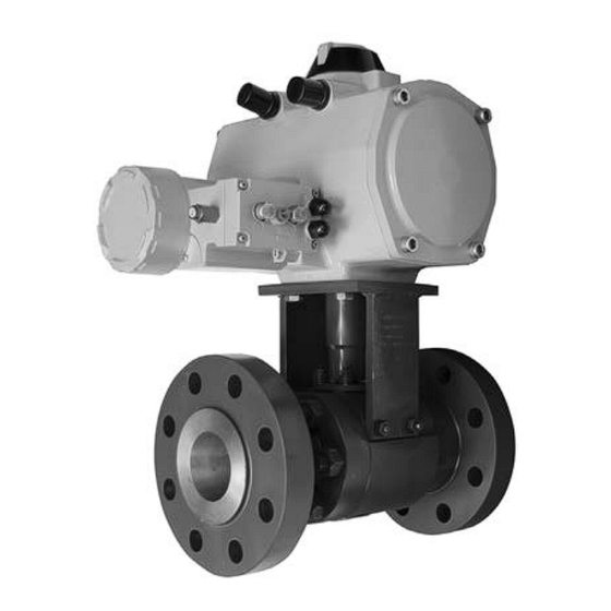
This instruction manual provides installation, operation, maintenance, and parts information for the Fisher Z500
Severe Service Ball Valve (see figure 1).
Do not install, operate, or maintain Z500 valves without being fully trained and qualified in valve, actuator, and
accessory installation, operation, and maintenance. To avoid personal injury or property damage, it is important to
carefully read, understand, and follow all the contents of this manual, including all safety cautions and warnings. If you
have any questions about these instructions, contact your
proceeding.
Description
The Z500 severe service ball valve is a split body bolted design, full or reduced port, with a blowout proof shaft. It can
be lever operated, gear operated, or actuated. The Z500 severe service ball valve line is a simplistic two-piece floating
ball design with integral metal seat meant to provide tight metal seating shutoff in high temperature, high pressure,
corrosive, and erosive applications across all industries.
Specifications
Specifications for these valves are shown in table 1.
www.Fisher.com
. . . . . . . . . . . . . . . . . . . . . . .
Figure 1. Fisher Z500 Severe Service Ball Valve
1
1
1
1
5
7
8
9
10
13
18
18
X1243
Emerson sales office
or Local Business Partner before
Z500 Valve
July 2017
Advertisement
Table of Contents

Related Manuals for Fisher Z500


Summary of Contents for Fisher Z500
-
Page 1: Table Of Contents
Description The Z500 severe service ball valve is a split body bolted design, full or reduced port, with a blowout proof shaft. It can be lever operated, gear operated, or actuated. The Z500 severe service ball valve line is a simplistic two-piece floating ball design with integral metal seat meant to provide tight metal seating shutoff in high temperature, high pressure, corrosive, and erosive applications across all industries. - Page 2 Valve Sizes Packing Constructions Z500: NPS J 1/2, J 3/4, J 1, J 1-1/2, J 2, J 3, Carbon Steel Valve Bodies: Wire reinforced graphite 4, J 6, J 8, J 10, J 12, J 14, J 16, J 18, J 20,...
- Page 3 Instruction Manual Z500 Valve D103803X012 July 2017 Table 3. Spray and Fused Coating Standard Construction Materials VALVE BODY AND END ADAPTER MATERIAL PART SA105 F316 Ball and Upstream Seat S31600 Shaft N07718 Nitrided AISI 660 Nitrided Spring and Body Gasket...
- Page 4 Instruction Manual Z500 Valve July 2017 D103803X012 Table 4. Valve Body Materials, End Connections, and Ratings (continued) Ratings Bore (inches) Size, NPS End Connection Valve Body Materials 0.65 1-1/2 Buttweld, Socketweld, FNPT, 1-1/2 RF, RTJ 1.15 2-1/2 1-1/2 2-1/2 Buttweld, RF, RTJ...
-
Page 5: Installation
Instruction Manual Z500 Valve D103803X012 July 2017 Installation WARNING Always wear protective gloves, clothing, and eyewear when performing any installation operations to avoid personal injury. Personal injury or equipment damage caused by sudden release of pressure may result if the valve assembly is installed where service conditions could exceed either the valve body rating or the mating pipe flange joint rating. - Page 6 Instruction Manual Z500 Valve July 2017 D103803X012 d. Customer shall ensure valve shaft has not been pushed or forced down into the valve e. Customer shall ensure no binding occurs when mounting the actuator i. Customer shall ensure the correct alignment is done when mounting the actuator ii.
-
Page 7: Operation
Instruction Manual Z500 Valve D103803X012 July 2017 Procedure Initial Preparation 1. Ensure the valve is in the fully open position so that vital sealing areas of the ball are not exposed to weld spatter. 2. Never make arc strikes on the valve body or end adapter except inside the groove intended for butt welding or inside the corner of the joint for socket welding. -
Page 8: Maintenance
Instruction Manual Z500 Valve July 2017 D103803X012 2. Actuators supplied with the valve may require maintenance per the actuator manufacturer's recommendations. For valves supplied with gears, the grease in the gearbox might need to be cleaned out and replaced periodically. Use only high temperature grease recommended for gearboxes. -
Page 9: Troubleshooting
Instruction Manual Z500 Valve D103803X012 July 2017 Troubleshooting Operation D Shaft adapter/actuator may be misaligned-- Remove actuator and shaft adapter, then reassemble per assembly procedures for actuators. D Over-tightened shaft packing-- Loosen packing to hand tight, cycle valve and retighten per procedures following torque table 6. -
Page 10: Packing Replacement
Instruction Manual Z500 Valve July 2017 D103803X012 Figure 2. Bolting Tightening Pattern Valve Leaking through Ball or Seating Area D Valve body ID or bore is clogged-- Flush or clean valve ID and try to cycle valve. D Valve is not fully closed-- Close valve, taking care not to over torque. - Page 11 Instruction Manual Z500 Valve D103803X012 July 2017 Figure 3. Z500 Construction Features LOCKPLATE METAL BODY SUPPORT BUSHING GASKET (HIGH CYCLE BRACKET ONLY) SEAT HOLDER SHAFT ADAPTER INTEGRAL METAL SEAT SIDE-MOUNTED BRACKET UPSTREAM SEAT BELLEVILLE END ADAPTER SPRING SHAFT PACKING STUD...
- Page 12 Instruction Manual Z500 Valve July 2017 D103803X012 1. Loosen the packing studs. 2. Remove the packing rings from the packing box, being careful not to damage the packing box. 3. Inspect the clean packing box to ensure all surfaces are clean and undamaged.
-
Page 13: Actuator Mounting
Instruction Manual Z500 Valve D103803X012 July 2017 Figure 6. Use Packing Flange 8. Bolt up the packing flange. Use Belleville washers in the same orientation as removed. Contact your Emerson sales office or Local Business Partner for additional information. Make sure that the markings on the studs and nuts are facing out. - Page 14 Instruction Manual Z500 Valve July 2017 D103803X012 Figure 8. Mount the Shaft Adapter Figure 9. Position the Mounting Bracket 3. Place the actuator on top of the mounting bracket and shaft adapter, in the fail position. Make sure the actuator is properly aligned with the shaft adapter.
- Page 15 Instruction Manual Z500 Valve D103803X012 July 2017 Figure 10. Place the Actuator on Top of the Mounting Bracket Figure 11. Install the Handwheel Hand Lever 6. Position the mounting bracket onto the body. Use anti-seize lubricant on the bracket studs and nuts. Make sure the markings on the studs and nuts are facing out.
- Page 16 Instruction Manual Z500 Valve July 2017 D103803X012 Figure 12. Shaft Adapter 9. Place the lock plate on top of the mounting bracket. Note the orientation of the open “O” and closed “C” markings. Figure 13. Lock Plate 10. Thread on the socket head cap screws, using anti-seize lubricant, from the underside of the mounting bracket.
- Page 17 Instruction Manual Z500 Valve D103803X012 July 2017 Table 6. Packing Flange Bolt Torque Values BOLT SIZE RECOMMENDED TORQUE Inch lbf•ft lbf•in N•m 5/16 7/16 1200 1800 Table 7. Assembly Stand Off NOMINAL BORE SIZE STANDOFF - MINIMUM STANDOFF - MAXIMUM...
-
Page 18: Parts Ordering
Use only genuine Fisher replacement parts. Components that are not supplied by Emerson Automation Solutions should not, under any circumstances, be used in any Fisher valve, because they will void your warranty, might adversely affect the performance of the valve, and could give rise to personal injury and property damage. -
Page 19: D103803X012 July
Instruction Manual Z500 Valve D103803X012 July 2017 Figure 15. Fisher Z500 Valve Assembly... - Page 20 Responsibility for proper selection, use, and maintenance of any product remains solely with the purchaser and end user. Fisher is a mark owned by one of the companies in the Emerson Automation Solutions business unit of Emerson Electric Co. Emerson Automation Solutions, Emerson, and the Emerson logo are trademarks and service marks of Emerson Electric Co.
Need help?
Do you have a question about the Z500 and is the answer not in the manual?
Questions and answers