
Related Manuals for Phoenix Contact FL SWITCH LM 5TX


Summary of Contents for Phoenix Contact FL SWITCH LM 5TX
- Page 1 AUTOMATION User manual UM EN FL SWITCH LM Order No.: 2888851 Hardware and software for Lean Managed Switches...
-
Page 3: User Manual
FL SWITCH LM 4TX/2FX / FL SWITCH LM 4TX/2FX-E 2832658 / 2891660 FL SWITCH LM 4TX/2FX SM / FL SWITCH LM 4TX/2FX SM-E 2891916 / 2891864 FL SWITCH LM 5TX 2989527 FL SWITCH LM 4TX/2FX ST 2989132 FL SWITCH LM 4TX/2FX SM ST... - Page 4 Phoenix Contact accepts no liability for erroneous handling or damage to products from Phoenix Contact or third-party products resulting from disregard of information contained in this manual.
- Page 5 The receipt of technical documentation (in particular data sheets, installation instructions, manuals, etc.) does not constitute any further duty on the part of Phoenix Contact to furnish information on alterations to products and/or technical documentation. Any other agreement shall only apply if expressly confirmed in writing by Phoenix Contact.
- Page 6 Phoenix Contact. Violators are liable for damages. Phoenix Contact reserves all rights in the case of patent award or listing of a registered design. Third-party products are always named without reference to patent rights. The existence of such rights shall not be excluded.
-
Page 7: Table Of Contents
Requirements for the use of WBM ............3-4 3.2.3 Functions/information in WBM ............3-5 3.2.4 Carrying out the firmware/software update ......... 3-9 Simple Network Management Protocol (SNMP)..........3-20 3.3.1 General function ................3-20 3.3.2 Diagram of SNMP management ............3-22 7278_en_04 PHOENIX CONTACT... - Page 8 Current VLANs ....................6-4 6.4.1 Static VLANs ..................6-5 6.4.2 VLAN Port Configuration ..............6-6 6.4.3 VLAN Port Configuration Table ............6-6 Creating static VLANs ..................6-7 VLAN and (R)STP ....................6-8 Technical data ........................7-1 Ordering data ..................... 7-3 PHOENIX CONTACT 7278_en_04...
-
Page 9: Lean Managed Switch
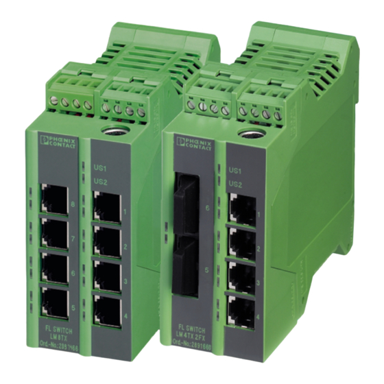
The Lean Managed Switch (LMS) is an Ethernet switch, which is suitable for industrial use. The LMS has five, six or eight ports, various versions available: – FL SWITCH LM 5TX with five RJ45 ports – FL SWITCH LM 8TX(-E) with eight RJ45 ports –... -
Page 10: Front View/Operating Elements/ Slots For The Lms
Supply voltage connection Alarm contact/ functional earth ground (optional) connection Mini-DIN V.24 (RS-232) Snap-on mechanism Status/ diagnostic indicators (supply) Port numbering Status/ diagnostic indicators (Ethernet) Ethernet ports 75500001 MAC address Figure 1-2 Front view/operating elements/slots for the LMS PHOENIX CONTACT 7278_en_04... -
Page 11: Dimensions Of The Lms
1.1.2 Dimensions of the LMS 112 mm (4.409") 45 mm (1.772") FL SWITCH LM 8TX FL SWITCH 5 TX Ord. No.2832085 Ord.-No.2832632 72780002 Figure 1-3 Housing dimensions of the LMS in millimeters (inches) 7278_en_04 PHOENIX CONTACT... -
Page 12: Status And Diagnostic Indicators
MAC address clearing Firmware 2.02 offers the following additional functions: – Optimized IGMP function, query port is not entered in GDA – Optimized Rapid Spanning Tree Protocol (RSTP), RSTP function optimized in connection with glass fiber FX port. PHOENIX CONTACT 7278_en_04... -
Page 13: Mounting/Removal
Mount the LMS on a clean DIN rail according to DIN EN 50 022 (e.g., NS 35 ... from Phoenix Contact). To avoid contact resistance only use clean, corrosion-free DIN rails. Before mounting the modules, an end clamp (E/NS 35N, Order No. 0800886) should be mounted on the left-hand side next to the LMS to stop the modules from slipping on the DIN rail. -
Page 14: Mounting
Pull down the positive latches using a suitable tool (e.g., screwdriver). Both positive latches remain snapped out. Then swivel the bottom of the module away from the DIN rail slightly (A). Next, lift the module upwards away from the DIN rail (B). Figure 1-5 Removing the LMS PHOENIX CONTACT 7278_en_04... -
Page 15: Installing The Lean Managed Switch
If redundant power supply monitoring is active (default setting), an error is indicated if only one voltage is applied. A bridge between US1 and US2 prevents this error message. It is also possible to deactivate monitoring in web-based management. opt. opt. 24 V DC 24 V DC Figure 1-6 LMS supply 7278_en_04 PHOENIX CONTACT... -
Page 16: Alarm Contact
In the event of non-redundant power supply, the switch indicates a supply voltage failure by opening the alarm contact. This error message can be prevented by connecting the supply voltage to both terminals in parallel, as shown in Figure 1-6, or by deactivating redundant power supply monitoring in web-based management. PHOENIX CONTACT 7278_en_04... -
Page 17: Rs-232) Interface For External Management
Option: In an environment particularly prone to EMI, noise immunity can be increased by an additional low-impedance connection to functional earth ground via terminal 7 ("Assignment of the COMBICON connector" on page 1-7). 7278_en_04 PHOENIX CONTACT... - Page 18 FL SWITCH LM ... 1-10 PHOENIX CONTACT 7278_en_04...
-
Page 19: Startup And Functions
"BootP" function is activated. The assignment of valid IP parameters is vital to the management function of the switch. Options for assigning IP parameters: – Configuration via the BootP protocol (default upon delivery) – Static configuration via the management interfaces 7278_en_04 PHOENIX CONTACT... - Page 20 The empty cells in the table are not relevant to the network class and are already used for the network address. Bit 1 Bit 2 Bit 3 Bit 4 Bit 5 Class A Class B Class C Class D Class E PHOENIX CONTACT 7278_en_04...
- Page 21 Class C Network ID Host ID 192.0.0.0 - 223.255.255.255 28 bits Class D Identifier for multicast group 224.0.0.0 - 239.255.255.255 27 bits Class E Reserved for future applications 240.0.0.0 - 247.255.255.255 Figure 2-2 Structure of IP addresses 7278_en_04 PHOENIX CONTACT...
- Page 22 (in the same position) set to "one", which is reflected in the IP address for the network class. Example: An IP address from Class A contains a 1-byte network address and a 3-byte computer address. Therefore, the first byte of the subnet mask may only contain "ones". PHOENIX CONTACT 7278_en_04...
- Page 23 0101 1001.1110 1010.0101 0101.0011 0010 Result: 0101 1001.1110 1010.0100 0000.0000 0000 Subnetwork After ANDing, the software determines that the relevant subnetwork (01) does not correspond to the local subnetwork (11) and the data telegram is forwarded to a subnetwork router. 7278_en_04 PHOENIX CONTACT...
-
Page 24: Flowchart After A Restart
FL SWITCH LM ... 2.1.3 Flowchart after a restart 2.1.3.1 Loading the configuration data System start Data in Flash valid? Load default values Load data from Flash Boot process completed? 70562008 Save data Figure 2-3 Flowchart: Loading the configuration data PHOENIX CONTACT 7278_en_04... - Page 25 BootP? Is there a valid local IP address? Entry of IP parameters as local configuration Start with local configuration data, as long as valid data is available 72780013 Startup completed Figure 2-4 Flowchart: Assigning IP parameters 7278_en_04 PHOENIX CONTACT...
-
Page 26: Frame Switching
The LMS can learn up to 1023 addresses and stores them in its table. The switch monitors the age of the learned addresses. The switch automatically deletes address entries from its address table that have exceeded a specific age (48 seconds, aging time). All learned entries are deleted on a restart. PHOENIX CONTACT 7278_en_04... -
Page 27: Prioritization (Quality Of Service)
Data packets with values between "0" and "3" in the priority field are low (default) priority – Data packets with values between "4" and "7" in the priority field are transmitted via the switch with high priority 7278_en_04 PHOENIX CONTACT... - Page 28 This function prevents delays in high-priority data transmission, due to large volumes of low- priority data traffic. Low-priority traffic is rejected when the memory or data channel is overloaded. 2-10 PHOENIX CONTACT 7278_en_04...
-
Page 29: Configuration And Diagnostics
Factory Manager and displayed in the message window. If you are operating other devices in the same network, messages from these devices may also be displayed. Messages from Phoenix Contact Factory Line components can be easily identified by their MAC address, which starts with 00.A0.45... and is provided on the devices. - Page 30 Under "Description", select an icon and enter a device name. Specify the desired IP parameters under "TCP/IP" (see also "Assigning IP parameters" on page 3-1). Figure 3-2 Input mask for IP parameters Make sure that the assignment of IP parameters via BootP is also activated. PHOENIX CONTACT 7278_en_04...
- Page 31 "OK" you will no longer have access via the Factory Manager. Restarting the LMS activates the modified parameters and restores access. To activate the new addresses after a restart, BootP must be activated in the LMS. 7278_en_04 PHOENIX CONTACT...
-
Page 32: Web-Based Management (Wbm)
After having entered the valid password, no further entry of the password is necessary for a period of 300 s (default). After this period of time has elapsed or after clicking on "Logout", the password must be re-entered. PHOENIX CONTACT 7278_en_04... -
Page 33: Functions/Information In Wbm
The navigation tree provides direct access to the following four areas: – General Instructions Basic information about WBM. – Device Information General device information. – General Configuration General device configuration. – Switch Station Device-specific configuration and diagnostics. 7278_en_04 PHOENIX CONTACT... -
Page 34: General Instructions
Contains a brief description of WBM and a navigation tree (site map), which is linked to every page of WBM. 3.2.3.2 Device Information Figure 3-5 "Device Information" web page "General" menu This page contains a range of static information about the device and the manufacturer. PHOENIX CONTACT 7278_en_04... - Page 35 "Local Diagnostics" menu This page describes the meaning of the diagnostic and status indicators. Figure 3-6 "Local Diagnostics" web page "Serial Port" menu This page lists the transmission parameters for serial communication. Figure 3-7 "Serial Port" web page 7278_en_04 PHOENIX CONTACT...
- Page 36 "Apply" you will no longer have access via the IP address set in the browser. "SNMP Configuration" menu System Information This part of the table is used to display or modify user-specific device data, e.g., location, device name or function. Figure 3-9 "SNMP Configuration" web page PHOENIX CONTACT 7278_en_04...
-
Page 37: Carrying Out The Firmware/Software Update
Save the desired firmware/software in the download directory of your TFTP server. If you use the Factory Manager, the path for standard installation is as follows: "C:\Program Files\Phoenix Contact\Factory Manager\Version 2.3\download". • Start the Factory Manager and check whether the TFTP server is activated. - Page 38 NOTE: A voltage failure during a firmware update results in the destruction of the firmware on the LMS. An update via XMODEM is required, see "Starting with faulty software" on page 3-52. 3-10 PHOENIX CONTACT 7278_en_04...
- Page 39 The password must be between four and twelve characters long. Please note that the password is always transmitted via the network in unencrypted format. Forgotten your password? Call the Phoenix Contact phone number listed in the Appendix, making sure you have the device serial number and MAC address to hand. "User Interfaces" menu The following actions can be executed here: –...
- Page 40 "Save current configuration" command overwrites the previously loaded configuration and instead saves the active configuration of the LMS. Set default upon delivery This option can be used to reset the switch to its default settings (default upon delivery) by entering a valid password. 3-12 PHOENIX CONTACT 7278_en_04...
- Page 41 "Port Configuration Table" menu This menu provides an overview of the important configuration settings for all ports and also provides the option to set the status, transmission mode, and link monitoring function for all existing ports. 3-13 7278_en_04 PHOENIX CONTACT...
- Page 42 Port Configuration Individual configuration option for each port. To view detailed data traffic statistics for the selected port, click on "Port Statistics". Even if the port is switched off, the Link LED for the port remains active. 3-14 PHOENIX CONTACT 7278_en_04...
- Page 43 Configuration and diagnostics Figure 3-19 "Port Configuration" web page 3-15 7278_en_04 PHOENIX CONTACT...
- Page 44 "Port Statistics" menu This menu provides detailed statistical information about the volume of data for each individual port. On this page, additional counter states can be set to zero for all ports. Figure 3-20 "Port Statistics" web page 3-16 PHOENIX CONTACT 7278_en_04...
- Page 45 10 Mbps. Therefore, with the same volume of data the destination port reaches a capacity of 50%. "Diagnostics/Display" menu The "Display" menu contains some status information about the switch. Figure 3-22 "Display" menu 3-17 7278_en_04 PHOENIX CONTACT...
- Page 46 Here, the network capacity of each individual port is displayed as a bargraph. The display is automatically updated according to the refresh interval. Figure 3-24 "Utilization" web page Please note that the % scale is spread according to the capacity utilization. 3-18 PHOENIX CONTACT 7278_en_04...
- Page 47 10 Mbps. Therefore, with the same volume of data the destination port reaches a capacity of 50%. 3.2.4.2 Rapid Spanning Tree For information about (Rapid) Spanning Tree, please refer to Section 4 "Rapid Spanning Tree". 3-19 7278_en_04 PHOENIX CONTACT...
-
Page 48: Simple Network Management Protocol (Snmp)
ID (object name and parameters) and can be published. If an object is no longer needed, it can be labeled as "expired", but it cannot be reused with other parameters under any circumstances. Phoenix Contact provides notification of ASN1 SNMP objects by publishing their descriptions on the Internet. 3-20... - Page 49 The IP addresses that are to receive these traps (trap targets/receivers) must be set by the user on the relevant device. The following traps are used: trapColdStart 1.3.6.1.6.3.1.1.5.1 Description Sent when the switch is started trapPortUp/Down 1.3.6.1.6.3.1.5.3/4 Description Sent when a port is switched on or off. 3-21 7278_en_04 PHOENIX CONTACT...
-
Page 50: Diagram Of Snmp Management
Agent Agent Agent FL IL 24 BK-B FL IL 24 BK-B FL IL 24 BK-B Ord.-No.: 2833000 Ord.-No.: 2833000 Ord.-No.: 2833000 FAIL FAIL FAIL LINK LINK LINK 10/100 10/100 10/100 72780015 Figure 3-25 Diagram of SNMP 3-22 PHOENIX CONTACT 7278_en_04... - Page 51 Tree structure of the MIB Not all devices support all object classes. If an unsupported object class is requested, "not supported" is generated. If an attempt is made to modify an unsupported object class, the message "badValue" is generated. 3-23 7278_en_04 PHOENIX CONTACT...
-
Page 52: Rfc1213-Mib - Mib Ii
This value is located in the SMI enterprises subtree (1.3.6.1.4.1) and describes which type of device is being managed. For example, if the manufacturer "Phoenix Contact GmbH" is assigned subtree 1.3.6.1.4.1.4346, it can then assign its bridge the identifier 1.3.6.1.4.1.4346.2.1. - Page 53 A node, which is a host and provides application services, has the value (2 ) + (2 ) = 72. sysORLastChange 1.3.6.1.2.1.1.8 Syntax TimeTicks Access Read Description Indicates the value of the sysUpTime during the last system modification. 3-25 7278_en_04 PHOENIX CONTACT...
-
Page 54: Bridge Mib (1.3.6.1.2.1.17)
Bridge MIB (1.3.6.1.2.1.17) 3.3.4.1 dot1dBase (1.3.6.1.2.1.17.1) The dot1dBase group contains bridge-specific information. (1) dot1dBaseBridgeAddress (2) dot1dBaseNumPorts (3) dot1dBasePortType (4) dot1dBasePortTable -- dot1dBasePortEntry -- (1) dot1dBasePort -- (2) dot1dBasePortIfIndex -- (3) dot1dBasePortPortCircuit -- (4) dot1dBasePortDelayExceededDiscards -- (5) dot1dBasePortMtuExceededDiscards 3-26 PHOENIX CONTACT 7278_en_04... - Page 55 -- (15) dot1dStpPortOperPointToPoint -- (16) dot1dStpPortAdminPathCost 3.3.4.3 dot1dTp (1.3.6.1.2.1.17.4) The dot1dTp group contains bridge-specific information. (1) dot1dTpLearnedEntryDiscards (2) dot1dTpAgingTime (3) dot1dTpFdbTable -- (1) dot1dTpFdbEntry -- (1) dot1dTpFdbAddress -- (2) dot1dTpFdbPort -- (3) dot1dTpFdbStatus (4) dot1dTpPortTable -- dot1dTpPortEntry 3-27 7278_en_04 PHOENIX CONTACT...
-
Page 56: Private Mibs
All configuration modifications, which are to take effect after an LMS restart, must be saved permanently using the "flWorkFWCtrlConfSave" object. MIB tree The private MIB from Phoenix Contact is integrated in the MIB tree as follows (see red arrow). Figure 3-27 MIB tree 3.3.5.1... - Page 57 Configuration and diagnostics pxcBasicName 1.3.6.1.4.1.4346.2.1.1 Syntax Display string Access Read Description Contains the manufacturer's name: Phoenix Contact GmbH & Co. KG. pxcBasicDescr 1.3.6.1.4.1.4346.2.1.2 Syntax Display string Access Read Description Contains the manufacturer's name and address: Phoenix Contact GmbH & Co. KG, D-32823 Blomberg.
- Page 58 Generates a table containing information about a Factory Line component. flComponentsIndex 1.3.6.1.4.1.4346.11.1.2.1.1.1 Syntax Integer32 (1 - 1024) Access Read Description Identifies the components for which this entry contains information. flComponentsName 1.3.6.1.4.1.4346.11.1.2.1.1.2 Syntax Display string Access Read Description Contains the device designation of the component. 3-30 PHOENIX CONTACT 7278_en_04...
- Page 59 Contains a brief description of the component. flComponentsURL 1.3.6.1.4.1.4346.11.1.2.1.1.4 Syntax Display string Access Read Description Contains the URL of a Phoenix Contact website with additional information. flComponentsOrderNumber 1.3.6.1.4.1.4346.11.1.2.1.1.5 Syntax Display string Access Read Description Contains the Order No. of the component.
- Page 60 1.3.6.1.4.1.4346.11.11.1.11 Syntax Integer 32 Access Read Description Contains the maximum number of interfaces that can be connected in theory. flWorkBasicCompCapacity 1.3.6.1.4.1.4346.11.11.1.12 Syntax Integer 32 Access Read Description Contains the number of interfaces actually connected. flWorkComponentsGroup 1.3.6.1.4.1.4346.11.11.2 3-32 PHOENIX CONTACT 7278_en_04...
- Page 61 1.3.6.1.4.1.4346.11.11.2.1.1.4 Syntax Integer (0 - 255) Access Read Description Contains the interface designation assigned by the manufacturer. flWorkNet 1.3.6.1.4.1.4346.11.11.4 flWorkNetlfParameter 1.3.6.1.4.1.4346.11.11.4.1 flWorkNetIfParamPhyAddress 1.3.6.1.4.1.4346.11.11.4.1.1 Syntax MAC address Access Read Description Contains the MAC address of the switch. 3-33 7278_en_04 PHOENIX CONTACT...
- Page 62 Integer32 (1 - 1024) Access Read Description Indicates whether the IP parameters have been modified but not saved: - No change - Address setting modified, but not yet activated Address settings must be saved permanently using the "flWorkFWCtrlConfSave" object. 3-34 PHOENIX CONTACT 7278_en_04...
- Page 63 Contains the number of available ports depending on the configuration of the LMS. flWorkNetPortTable 1.3.6.1.4.1.4346.11.11.4.2.2 flWorkNetPortEntry 1.3.6.1.4.1.4346.11.11.4.2.2.1 Description Generates a table with a detailed description of the port configuration. flWorkNetPortIndex 1.3.6.1.4.1.4346.11.11.4.2.2.1.1 Syntax Integer32 (1 - 1024) Access Read 3-35 7278_en_04 PHOENIX CONTACT...
- Page 64 Octet string (0 - 16) Access Read/write Description Contains the "name" of the port assigned by the user, e.g., "Robot 1". flWorkNetPortEnable 1.3.6.1.4.1.4346.11.11.4.2.2.1.7 Syntax Integer Access Read/write Description Here you can disable the port: Port disabled Port enabled flWorkNetPortModus 1.3.6.1.4.1.4346.11.11.4.2.2.1.9 3-36 PHOENIX CONTACT 7278_en_04...
- Page 65 Specifies the "name" of the module. flWorkNetPortInterfaceName 1.3.6.1.4.1.4346.11.11.4.2.2.1.15 Syntax Octet string Access Read Description Specifies the "name" of the interface. flWorkNetPortStpMode 1.3.6.1.4.1.4346.11.11.4.2.2.1.18 Syntax Integer Access Read Description Specifies the port mode during redundancy operation: Spanning Tree Rapid Spanning Tree 3-37 7278_en_04 PHOENIX CONTACT...
- Page 66 Contains the creation time of the firmware version as a string. Example for "14:10:20": 0x31, 0x34, 0x31, 0x30, 0x32, 0x30. flWorkFWInfoCopyright 1.3.6.1.4.1.4346.11.11.11.1.5 Syntax Display string Access Read Description Contains the owner of the firmware copyright. Copyright by Phoenix Contact GmbH & Co., 2003. 3-38 PHOENIX CONTACT 7278_en_04...
- Page 67 0x30, 0x39, 0x30, 0x33, 0x30, 0x31. flWorkFWInfoBootTime 1.3.6.1.4.1.4346.11.11.11.1.9 Syntax Octet string Access Read Description Contains the creation time of the boot loader version as a string. Example for "14:10:20": 0x31, 0x34, 0x31, 0x30, 0x32, 0x30. flWorkFWCtrl 1.3.6.1.4.1.4346.11.11.11.2 flWorkFWCtrlBasic 1.3.6.1.4.1.4346.11.11.11.2.1 3-39 7278_en_04 PHOENIX CONTACT...
- Page 68 Syntax Access Description Generates a table with the IP addresses of the trap managers. flWorkFWCtrlTrapDestIndex 1.3.6.1.4.1.4346.11.11.11.2.2.1.1.1 Syntax Integer32 (1 - 1024) Access Read Description Contains the index of the target component, which should receive the traps. 3-40 PHOENIX CONTACT 7278_en_04...
- Page 69 Read Description Contains the maximum permissible number of trap receivers. flWorkFWCtrlTrapDestEnable 1.3.6.1.4.1.4346.11.11.11.2.2.3 Syntax Integer Access Read/write Description This object can be used to disable the "send SNMP traps" function: Sending permitted Sending not permitted flWorkFWCtrlPasswd 1.3.6.1.4.1.4346.11.11.11.2.3 3-41 7278_en_04 PHOENIX CONTACT...
- Page 70 Default Range 30 - 3600 flWorkFWCtrlUpdate 1.3.6.1.4.1.4346.11.11.11.2.4 flWorkFWCtrlTftpIpAddr 1.3.6.1.4.1.4346.11.11.11.2.4.2 Syntax IP address Access Read/write Description This object can be used to set the IP address of the TFTP server. 3-42 PHOENIX CONTACT 7278_en_04...
- Page 71 1.3.6.1.4.1.4346.11.11.11.2.4.6 Syntax Integer Access Read Description This object can be used to request the status of the firmware update: Firmware update not started Executing firmware update Firmware update successful Connection error Incorrect path/file name Error 3-43 7278_en_04 PHOENIX CONTACT...
- Page 72 This object can be used to set the device to the default settings (basic settings - see 2.1.1 on page 2-1). It also triggers a restart: Do not reset to default settings Reset to default settings flWorkFWCtrlSerial 1.3.6.1.4.1.4346.11.11.11.2.6 3-44 PHOENIX CONTACT 7278_en_04...
- Page 73 2 bits flWorkFWCtrlSerialParity 1.3.6.1.4.1.4346.11.11.11.2.6.4 Syntax Integer Access Read Description Contains the parity mode for the serial interface: None Even flWorkFWCtrlSerialFlowControl 1.3.6.1.4.1.4346.11.11.11.2.6.5 Syntax Integer Access Read Description Contains the selected flow control for the serial interface: None Hardware 3-45 7278_en_04 PHOENIX CONTACT...
- Page 74 This object controls the deletion of the unicast table. If this object is set to "2", the switch immediately deletes its unicast table. The switch then relearns and creates a new table. The object is always set to "1". Default Delete unicast table 3-46 PHOENIX CONTACT 7278_en_04...
- Page 75 This object controls the deletion of the multicast table. If this object is set to "2", the switch immediately deletes its multicast table. The switch then relearns and creates a new table. The object is always set to "1". Default Delete multicast table 3-47 7278_en_04 PHOENIX CONTACT...
-
Page 76: Management Via Local V.24 (Rs-232) Communication Interface
Connect the PC and the switch using a suitable V.24 (RS-232) cable (PRG CAB MINI DIN, Order No. 2730611). Once you have made the connection, select the Ctrl + L key combination on the PC. The switch then requests the screen contents. 3-48 PHOENIX CONTACT 7278_en_04... -
Page 77: User Interface Functions
"SAVE" function to save the active configuration settings permanently. 3.4.2.3 Structure of the user interface screens Login Screen Login Screen - - - > Phoenix Contact Lean Managed Switch < - - - Phoenix Contact GmbH & Co. KG www.phoenixcontact.com Running switch application version: x.xx... - Page 78 This user interface screen can be used to determine the addressing mechanism or to trigger a device restart. All settings are transferred using "APPLY", but are not saved permanently. Use the "SAVE" function to save the active configuration settings permanently. 3-50 PHOENIX CONTACT 7278_en_04...
- Page 79 "Apply" or "Save". This undoes any changes to the configuration, and resets all IP parameters to the settings default upon delivery (see Section 2.1.1 on page 2-1). Resetting to the default settings also resets the password to "private". For security reasons, we recommend you enter a new, unique password. 3-51 7278_en_04 PHOENIX CONTACT...
-
Page 80: Starting With Faulty Software
Connect the switch to your PC via the serial V.24 (RS-232) interface. Make sure that your HyperTerminal is configured correctly (see configuration on page 3-48). - - - > Phoenix Contact Lean Managed Switch < - - - Phoenix Contact GmbH & Co. KG www.phoenixcontact.com... - Page 81 Configuration and diagnostics Press "a" to download the new software. The following message appears: - - - > Phoenix Contact Lean Managed Switch < - - - Phoenix Contact GmbH & Co. KG www.phoenixcontact.com ENTER ´a´ TO DOWNLOAD SWITCH SOFTWARE USING XMODEM PROTOCOL ENTER ´c´...
- Page 82 File transmission may take a few minutes. Do not perform any other actions while the box is open. Once the box has closed, a message appears in HyperTerminal. Enter "c" to continue with the boot process, or trigger a reset using the reset button. 3-54 PHOENIX CONTACT 7278_en_04...
-
Page 83: Rapid Spanning Tree
ACT 100 FD US1 GND US2 GND R1 R2 V.24 US1 GND US2 GND R1 R2 V.24 FL SWITCH 5 TX FL SWITCH LM 8TX Ord. No.2832085 Ord.-No.2832632 72780008 Figure 4-1 Possible tree structure with Rapid Spanning Tree 7278_en_04 PHOENIX CONTACT... -
Page 84: Rstp Startup
"General Configuration" menu, then the "User Interfaces" page. Activate the "Rapid Spanning Tree" function under "Redundancy" and confirm by entering your password. Figure 4-2 "User Interfaces" menu The previously created configuration is lost if "No redundancy" is selected in the WBM menu following RSTP configuration. PHOENIX CONTACT 7278_en_04... - Page 85 The "Maximum Age of STP Information", "Hello Time", and "Forward Delay" fields have the same meaning as for STP. These values are used when this switch becomes a root. The values currently used can be found under RSTP General. 7278_en_04 PHOENIX CONTACT...
- Page 86 Forward Delay The forward delay value indicates how long the switch is to wait in order for the port state in STP mode to change from "Discarding" to "Listening" and from "Listening" to "Learning" (2 x forward delay). PHOENIX CONTACT 7278_en_04...
- Page 87 The port does not take part in data transmission. – "Learning" The port does not take part in data transmission of the active topology, however, MAC addresses are learned. 4.2.1.2 RSTP Port Configuration Modifications of properties can result in complete reconfiguration of Rapid Spanning Tree. 7278_en_04 PHOENIX CONTACT...
- Page 88 The port ID consists of 4 bits for the port priority and 12 bits for the port number. The port ID is interpreted as an unsigned integer value. When comparing two port IDs, the one with the lowest numeric value is of higher, i.e., "better", priority. PHOENIX CONTACT 7278_en_04...
- Page 89 Here you can specify whether this port is to be operated as an edge port (default setting), if possible. Priority Indicates the priority set for this port. Due to backwards compatibility with STP, priority values can be set that are not configurable in RSTP. 7278_en_04 PHOENIX CONTACT...
- Page 90 "Learning" states are still available if the network is operated in mixed operation of STP and RSTP. Frame duplication Due to the fast switch-over times of RSTP, frames may be duplicated and the order of frames may be changed. PHOENIX CONTACT 7278_en_04...
- Page 91 All infrastructure components used in your network that do not actively support Spanning Tree must be transparent for Spanning Tree messages (BPDUs) and must forward all BPDUs to all ports without modifying them. When Spanning Tree is disabled, the switch is transparent for BPDUs. 7278_en_04 PHOENIX CONTACT...
-
Page 92: Rstp Fast Ring Detection
Structure of the ring ID The ring ID consists of the port number of the blocking port and the MAC address of the corresponding switch. Advantages of the ring ID: – Easier to identify redundant paths and locate blocking ports. 4-10 PHOENIX CONTACT 7278_en_04... -
Page 93: Connection Failure - Example
The ring extends over port 1 and port 2 for each switch. On switch 4, the loop is broken by a blocking port. If a cable interrupt occurs at the point indicated by the star, this produces the following entries on the "RSTP Fast Ring Detection" web page: Switch 3 - Failed on Port A 4-11 7278_en_04 PHOENIX CONTACT... - Page 94 US1 US2 FAIL Address 00.A0.45.1B.D2.1D 10 11 12 13 14 15 US1 GND US2 GND R1 R2 V.24 ACT 100 FD Reset 00A0451BDD Address Fail US1 GND V.24 687407052 Figure 4-10 Connection failure with RSTP ring detection 4-12 PHOENIX CONTACT 7278_en_04...
-
Page 95: Example Topologies
FL SWITCH LM 8TX MODE Ord. No.2832085 Ord.-No.2832632 US1 US2 FAIL Address 00.A0.45.1B.D2.1D 10 11 12 13 14 15 US1 GND US2 GND R1 R2 V.24 ACT 100 FD 72780010 Figure 4-11 Redundant coupling of network segments 4-13 7278_en_04 PHOENIX CONTACT... - Page 96 "STP Bridge Configuration" page in WBM for the switch selected as the root switch. Make sure that all the other network switches have a lower priority (higher value). Here, the set path costs are not evaluated. 4-14 PHOENIX CONTACT 7278_en_04...
- Page 97 Additional infrastructure components are connected to the port. The corresponding network segment does not contain any loops. Additional infrastructure components are connected to the port, forming a Rapid Spanning Tree of their own. No additional redundant connections to this network segment are permitted. 4-15 7278_en_04 PHOENIX CONTACT...
- Page 98 2 x Forward Delay - 1 s ≥ MaxAge – MaxAge ≥ 2 × Hello Time + 1 s – The value ((MaxAge/2) - Hello Time) for a ring topology corresponds to the maximum number of components with active Rapid Spanning Tree. 4-16 PHOENIX CONTACT 7278_en_04...
- Page 99 00A0451BDD 00A0451BDD Address Address Fail Fail setting the timer US1 GND V.24 US1 GND V.24 values 72780012 FL SWITCH LM 8TX FL SWITCH 5 TX Ord. No.2832085 Ord.-No.2832632 Figure 4-15 Example 2 for the "relevant path" 4-17 7278_en_04 PHOENIX CONTACT...
- Page 100 ≥ 6 s 10 s 22 s ≥ 11 s 20 s 42 s ≥ 16 s 30 s 62 s ≥ 21 s 40 s 82 s 20 s 15 s 50 s Bold/italic = Default 4-18 PHOENIX CONTACT 7278_en_04...
-
Page 101: Configuration Notes For Rapid Spanning Tree
– It is recommended that large tree support is not activated in networks with less than seven switches along the relevant path. 4-19 7278_en_04 PHOENIX CONTACT... -
Page 102: Large Tree Support Properties
00.A0.45.1B.D2.1D 10 11 12 13 14 15 US1 GND US2 GND R1 R2 V.24 ACT 100 FD FL SWITCH 5 TX FL SWITCH LM 8TX Ord. No.2832085 Ord.-No.2832632 Figure 4-16 Topology example for large tree support 4-20 PHOENIX CONTACT 7278_en_04... -
Page 103: Multicast Filtering
If there are no routers in the network, a suitably equipped switch can be used for the query function. 7278_en_04 PHOENIX CONTACT... - Page 104 This web page provides global settings for multicast support. Here, IGMP snooping can be activated and an aging time can be specified for IGMP snooping information. Figure 5-1 "General Multicast Configuration" web page Please note that the switch supports 50 multicast groups at any given time. PHOENIX CONTACT 7278_en_04...
- Page 105 By default, GMRP is activated as soon as IGMP snooping is activated. The switches that receive the GMRP packets do not have to support IGMP snooping in order to receive and evaluate the GMRP packets. 7278_en_04 PHOENIX CONTACT...
- Page 106 FL SWITCH LM ... PHOENIX CONTACT 7278_en_04...
-
Page 107: Virtual Local Area Network (Vlan)
In the WBM menu, the "VLAN" page - under which the function can be configured and activated - is enabled. When deactivating the VLAN configuration pages under "User Interfaces", the VLAN mechanism is not deactivated. The saved VLAN configuration is retained. 7278_en_04 PHOENIX CONTACT... -
Page 108: Management Vlan Id
Place another port (B) in the desired management VLAN. Port B must be an "untagged member" of the desired management VLAN. Set the corresponding port VLAN ID, if necessary. Set the desired VLAN ID as the management VLAN. Connect your PC to the switch via port B and save the configuration. PHOENIX CONTACT 7278_en_04... -
Page 109: General Vlan Configuration
After switching the VLAN mode from "Tagging" to "Transparent" or vice versa, the active configuration must be saved and a device reset triggered so that the modification becomes active. The current valid state can be read in the "Current Tagging Status" line. 7278_en_04 PHOENIX CONTACT... -
Page 110: Current Vlans
"The switch supports only 8 VLANs! Further VLANs will be refused!" VLAN 1 is always created statically and all ports are added to it as untagged members. PHOENIX CONTACT 7278_en_04... -
Page 111: Static Vlans
Ports with "Untagged" status belong to the selected VLAN and packets are sent to this port without VLAN tag. An "Untagged" port cannot belong to multiple VLANs - otherwise there is no logical division (except VLAN 1). - = None Ports with "None" status are not integrated into the VLAN. 7278_en_04 PHOENIX CONTACT... -
Page 112: Vlan Port Configuration
"VLAN Port Configuration" web page, where the settings can be modified. This table can be used to assign incoming packets to the created VLANs if the packets reached the port without VLAN tag. PHOENIX CONTACT 7278_en_04... -
Page 113: Creating Static Vlans
VLAN 5 between termination devices A and B. The type of termination device must be taken into consideration: VLAN-compatible (processes tags) or not VLAN-compatible (does not process tags). In the example, two types of termination device are take into consideration. 7278_en_04 PHOENIX CONTACT... -
Page 114: Vlan And (R)Stp
VLAN and (R)STP When using (R)STP and VLAN simultaneously, please note the following: – (R)STP is not based on VLANs – (R)STP creates a loop-free topology in the form of a tree structure PHOENIX CONTACT 7278_en_04... - Page 115 ACT 100 FD 00A0451BDD US1 GND US2 GND R1 R2 V.24 Address Fail US1 GND V.24 Manual configuration: VLAN2, port member: Tagged VLAN2, port member: Untagged Port VID: VLAN2 Figure 6-7 Typical configuration for VLAN and (R)STP 7278_en_04 PHOENIX CONTACT...
- Page 116 FL SWITCH LM ... 6-10 PHOENIX CONTACT 7278_en_04...
-
Page 117: Technical Data
For 1023 MAC addresses SNMP Version 1 and 2 Supported MIBs SNMPv2 MIB, RSTP MIB, and private SNMP objects from Phoenix Contact Housing dimensions (width x height x depth) 45 mm x 99 mm x 112 mm Permissible operating temperature -40°C to +70°C... - Page 118 Version 00: First version Version 01: LM-E switches added and functions of current firmware added Version 02: Extended to include functions for the current firmware Version 03: Extended to include new devices Version 04: Firmware 3.x included PHOENIX CONTACT 7278_en_04...
-
Page 119: Ordering Data
Ordering data Products Description Order designation Order No. Pcs./Pkt. Lean Managed Switch with 5 RJ45 ports FL SWITCH LM 5TX 2989527 Lean Managed Switch with 8 RJ45 ports FL SWITCH LM 8TX 2832632 FL SWITCH LM 8TX-E 2891466 Lean Managed Switch with 4 RJ45 ports and two FX ports in... - Page 120 FL PATCH GUARD KEY 2891521 Security element for FL CAT 5/6 PATCH ... FL PATCH SAFE CLIP 2891246 Phoenix Contact GmbH & Co. KG Flachsmarktstr. 8 32825 Blomberg Germany + 49 - 52 35 - 30 0 + 49 - 52 35 - 34 12 00 www.phoenixcontact.com...
Need help?
Do you have a question about the FL SWITCH LM 5TX and is the answer not in the manual?
Questions and answers