JVC UX-P400 Service Manual
Hide thumbs
Also See for UX-P400:
- Instructions manual (30 pages) ,
- Instructions manual (32 pages) ,
- Instructions manual (31 pages)
Table of Contents
Advertisement
SERVICE MANUAL
MICRO COMPONENT SYSTEM
6
2004
MB262
1
PRECAUTION. . . . . . . . . . . . . . . . . . . . . . . . . . . . . . . . . . . . . . . . . . . . . . . . . . . . . . . . . . . . . . . . . . . . . . . . . 1-3
2
SPECIFIC SERVICE INSTRUCTIONS . . . . . . . . . . . . . . . . . . . . . . . . . . . . . . . . . . . . . . . . . . . . . . . . . . . . . . 1-6
3
DISASSEMBLY . . . . . . . . . . . . . . . . . . . . . . . . . . . . . . . . . . . . . . . . . . . . . . . . . . . . . . . . . . . . . . . . . . . . . . . 1-7
4
ADJUSTMENT . . . . . . . . . . . . . . . . . . . . . . . . . . . . . . . . . . . . . . . . . . . . . . . . . . . . . . . . . . . . . . . . . . . . . . . 1-30
5
TROUBLE SHOOTING . . . . . . . . . . . . . . . . . . . . . . . . . . . . . . . . . . . . . . . . . . . . . . . . . . . . . . . . . . . . . . . . . 1-31
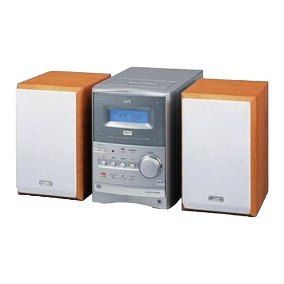
UX-P400
SP-UXP400
CA-UXP400
TABLE OF CONTENTS
COPYRIGHT © 2004 Victor Company of Japan, Limited
Area suffix
US ------------------------ Singapore
UF ------------------------------ China
UP ----------------------------- Korea
UT ---------------------------- Taiwan
UW ----------- Brazil,Mexico,Peru
SP-UXP400
No.MB262
2004/6
Advertisement
Table of Contents
Troubleshooting

Related Manuals for JVC UX-P400


Summary of Contents for JVC UX-P400
- Page 1 SERVICE MANUAL MICRO COMPONENT SYSTEM MB262 2004 UX-P400 Area suffix US ------------------------ Singapore UF ------------------------------ China UP ----------------------------- Korea UT ---------------------------- Taiwan UW ----------- Brazil,Mexico,Peru SP-UXP400 CA-UXP400 SP-UXP400 TABLE OF CONTENTS PRECAUTION............... . . 1-3 SPECIFIC SERVICE INSTRUCTIONS .
- Page 2 SPECIFICATION 40 W (20 W + 20 W) at 4 Ω (10% THD) Amplifier section Output Power 4 Ω - 16 Ω Speakers/Impedance Audio Input 400 mV/50 kΩ Tuner section FM tuning range 87.50 MHz - 108.00 MHz AM (MW) tuning range 531 kHz - 1 710 kHz (at 9 kHz intervals) 530 kHz - 1 710 kHz (at 10 kHz intervals) CD player section...
- Page 3 SECTION 1 PRECAUTION Safety Precautions (1) This design of this product contains special hardware and voltmeter. many circuits and components specially for safety purpos- Move the resistor connection to each exposed metal es. For continued protection, no changes should be made part, particularly any exposed metal part having a return to the original design unless authorized in writing by the path to the chassis, and measure the AC voltage across...
- Page 4 Preventing static electricity Electrostatic discharge (ESD), which occurs when static electricity stored in the body, fabric, etc. is discharged, can destroy the laser diode in the traverse unit (optical pickup). Take care to prevent this when performing repairs. 1.5.1 Grounding to prevent damage by static electricity Static electricity in the work area can destroy the optical pickup (laser diode) in devices such as laser products.
- Page 5 Important for laser products 5.CAUTION : If safety switches malfunction, the laser is able 1.CLASS 1 LASER PRODUCT to function. 2.DANGER : Invisible laser radiation when open and inter 6.CAUTION : Use of controls, adjustments or performance of lock failed or defeated. Avoid direct exposure to beam. procedures other than those specified here in may result in 3.CAUTION : There are no serviceable parts inside the hazardous radiation exposure.
- Page 6 SECTION 2 SPECIFIC SERVICE INSTRUCTIONS This service manual does not describe SPECIFIC SERVICE INSTRUCTIONS. 1-6 (No.MB262)
- Page 7 SECTION 3 DISASSEMBLY Main body section 3.1.1 Removing the side panels L/R (See Figs.1 to 4) (1) From the back side of the main body, remove the four screws A attaching the side panels L/R to the rear panel. Top cover assembly (See Fig.1.) (2) From the bottom side of the main body, remove the two screws B attaching the side panels L/R to the bottom chas-...
- Page 8 3.1.2 Removing the front panel assembly (See Figs.5 to 8) • Prior to performing the following procedures, remove the side panels L/R. (1) From the right side of the main body, push the slide cam and pull the tray out of the main body in the direction of the arrow 1.
- Page 9 3.1.3 Removing the top cover assembly (See Figs.9 and 10) • Prior to performing the following procedures, remove the side panels L/R and front panel assembly. Top cover assembly (1) From the back side of the main body, remove the screw D attaching the top cover assembly to the rear panel.
- Page 10 3.1.4 Removing the cassette mechanism assembly (See Fig.11) • Prior to performing the following procedures, remove the side panels L/R, front panel assembly and top cover assembly. Top cover assembly (1) From the bottom side of the top cover assembly, discon- Card wires nect the card wires from the connectors (CN33, CN34) on the head amp.
- Page 11 3.1.5 Removing the tuner (See Figs.12 and 13) • Prior to performing the following procedures, remove the side panel L. (1) From the back side of the main body, remove the two screws F attaching the tuner to the rear panel. (See Fig.12.) (2) Disconnect the card wire from the connector on the...
- Page 12 3.1.6 Removing the rear panel (See Fig.14) • Prior to performing the following procedures, remove the side CN711 panels L/R. (1) From the back side of the main body, remove the eight screws G attaching the rear panel. Wire (2) Release the engagement sections e and remove the rear panel.
- Page 13 3.1.8 Removing the main board (See Fig.16) Main board CN210 • Prior to performing the following procedures, remove the side panels L/R, front panel assembly, top cover assembly, tuner and rear panel. (1) From the right side of the main body, remove the two screws J attaching the main board.
- Page 14 3.1.10 Removing the power amplifier board (See Fig.18) • Prior to performing the following procedures, remove the side panels L/R, front panel assembly, top cover assembly, tuner, Power amplifier board rear panel, main board and power supply board. (1) From the top side of the main body, remove the four screws L attaching the power amplifier board.
- Page 15 3.1.12 Removing the CD mechanism assembly (See Figs.20 and 21) • Prior to performing the following procedures, remove the side panels L/R, front panel assembly, top cover assembly, tuner, Shield case Bottom chassis rear panel, main board and power supply board. (1) From the top side of the main body, remove the four screws P attaching the shield case to the bottom chassis.
- Page 16 3.1.13 Removing the power transformer (See Figs.22 and 23) • Prior to performing the following procedures, remove the side panels L/R, front panel assembly, top cover assembly and rear Power supply board panel. CN103 CN102 (1) From the forward side of the power supply board, discon- nect the wires from the connectors (CN102, CN103, CN105).
- Page 17 3.1.14 Removing the FL board (See Fig.24) • Prior to performing the following procedures, remove the side panels L/R and front panel assembly. FL board (1) From the inside of the front panel assembly, remove the four screws S attaching the FL board. (2) Take out the FL board from the front panel assembly and disconnect the card wire from the connector CN751...
- Page 18 3.1.15 Removing the switch board (See Figs.25 and 26) • Prior to performing the following procedures, remove the side panels L/R and front panel assembly. Front panel assembly (1) From the front side of the front panel assembly, pull out the mic volume knob.
- Page 19 3.1.16 Removing the headphone jack board (See Fig.27) • Prior to performing the following procedure, remove the side panels L/R and front panel assembly. Spacer Wire (1) From the inside of the front panel assembly, remove the screw U attaching the headphone jack board. Reference: After attaching the headphone jack board, fix the wire with the spacer.
- Page 20 CD mechanism section • Remove the CD mechanism assembly from the main body. (See "3.1.12 Removing the CD mechanism assembly".) 3.2.1 Removing the tray assembly (See Figs.1 to 3) (1) From the right side of the CD mechanism assembly, push the slide cam and pull the tray assembly out of the CD Tray assembly CD mechanism assembly...
- Page 21 (2) Disconnect the card wire from the connector CN602 on the CD servo board and take out the CD traverse mechanism CD mechanism assembly CD servo board assembly with the CD servo board. Traverse mechanism assembly CN602 Fig.4 (No.MB262)1-21...
- Page 22 3.2.3 Removing the CD servo board (See Figs.5 and 6) • Remove the traverse mechanism assembly. (1) From the bottom side of the traverse mechanism assem- Solder section c Wire (yellow) bly, remove the solders from the solder sections c. (See Fig.5) (2) Remove the wire (yellow) from the solder sections d.
- Page 23 3.2.4 Removing the CD pickup (See Figs.7 to 9) • Remove the traverse mechanism assembly. (1) From the top side of the traverse mechanism assembly, re- Shaft holder Joint h move the screw D attaching the shaft holder. (See Fig.7) (2) Release the joint h and take out the shaft holder.
- Page 24 3.2.5 Attaching the CD pickup (See Figs.7 to 10) • See "3.2.4 Removing the CD pickup". (1) Remove solders from the short land sections k after con- SS gear necting the card wire to the connector on the CD pickup. (See Fig.9) (2) Attach the shaft.
- Page 25 3.2.7 Removing the CD loading switch board (See Fig.12) (1) From the bottom side of the CD mechanism assembly, dis- connect the card wire from the connector on the CD CD loading switch board loading switch board. (2) Remove the wires from the solder section n on the CD Claw p Wire loading switch board.
- Page 26 Cassette mechanism assembly 3.3.1 Removing the Play/Record & Clear head Cassette mechanism assembly Fly wheelR (See Fig.1~3) (1) While moving the trigger arm on the right side of the head mount in the direction of the arrow, turn the flywheel R counterclockwise until the head mount comes ahead and clicks.
- Page 27 3.3.2 Removing the head amplifier & mechanism control board (See Fig.4) (1) Turn over the cassette mechanism assembly and remove Main motor assembly the three screws A attaching the head amplifier & mecha- nism control board. Capstan belt (2) Disconnect the flexible wire from connector CN31 on the head amplifier &...
- Page 28 3.3.4 Removing the flywheel (See Fig.8, 9) • Prior to performing the following procedure, remove the head amplifier & mechanism control board and the main motor as- sembly. (1) From the front side of the cassette mechanism, remove the slit washers attaching the capstan shaft L and R. Pull out the flywheels backward.
- Page 29 3.3.6 Reattaching the Play/ Record & Clear head (See Fig.11~13) (1) Reattaching the head mount assembly. a) Change front of the direction cover of the head mount assembly to the left (Turn the head forward). b) Fit the bosses O', P', Q', U' and V' on the head mount assembly to the holes P and V, the slots O, U and Q of the mechanism sub assembly (See Fig.11 to 13).
- Page 30 SECTION 4 ADJUSTMENT Jigs and test instruments • Remote controller Adjustment and check method 4.2.1 Initialize all data to the factory setting 4.2.4 Fan motor ON/OFF check Pressing the [STOP] , [SLEEP] and Pressing the [STOP] , [SLEEP] and [STANDBY/ON] together at Power [STANDBY/ON] together at Power ON condition.
-
Page 31: Trouble Shooting
SECTION 5 TROUBLE SHOOTING Flow of functional operation untill TOC read (CD) Check Point Slider turns REST Power ON Disc play Key Confirm that the voltage at SW ON. the pin68 of IC251 is 0V. (ON: 0V) Laser ON Detection of disc Automatic tuning of FO offset and TE offset Automatic measurement of Confirm that the Focus error... - Page 32 Maintenance of laser pickup (CD) Replacement of laser pickup (CD) (1) Cleaning the pick up lens Before you replace the pick up, please try to clean the lens Turn of the power switch and, disconnect the with a alcohol soaked cotton swab. power cord.
- Page 33 (No.MB262)1-33...
- Page 34 Victor Company of Japan, Limited AV & MULTIMEDIA COMPANY AUDIO/VIDEO SYSTEMS CATEGORY 10-1,1chome,Ohwatari-machi,Maebashi-city,371-8543,Japan (No.MB262) Printed in Japan...
-
Page 35: Table Of Contents
SERVICE MANUAL MICRO COMPONENT SYSTEM MB262 2004 UX-P400 Area suffix US ------------------------ Singapore UF ------------------------------ China UP ----------------------------- Korea UT ---------------------------- Taiwan UW ----------- Brazil,Mexico,Peru SP-UXP400 CA-UXP400 SP-UXP400 TABLE OF CONTENTS PRECAUTION............... . . 1-3 SPECIFIC SERVICE INSTRUCTIONS . - Page 36 SPECIFICATION 40 W (20 W + 20 W) at 4 Ω (10% THD) Amplifier section Output Power 4 Ω - 16 Ω Speakers/Impedance Audio Input 400 mV/50 kΩ Tuner section FM tuning range 87.50 MHz - 108.00 MHz AM (MW) tuning range 531 kHz - 1 710 kHz (at 9 kHz intervals) 530 kHz - 1 710 kHz (at 10 kHz intervals) CD player section...
-
Page 37: Precaution
SECTION 1 PRECAUTION Safety Precautions (1) This design of this product contains special hardware and voltmeter. many circuits and components specially for safety purpos- Move the resistor connection to each exposed metal es. For continued protection, no changes should be made part, particularly any exposed metal part having a return to the original design unless authorized in writing by the path to the chassis, and measure the AC voltage across... - Page 38 Preventing static electricity Electrostatic discharge (ESD), which occurs when static electricity stored in the body, fabric, etc. is discharged, can destroy the laser diode in the traverse unit (optical pickup). Take care to prevent this when performing repairs. 1.5.1 Grounding to prevent damage by static electricity Static electricity in the work area can destroy the optical pickup (laser diode) in devices such as laser products.
- Page 39 Important for laser products 5.CAUTION : If safety switches malfunction, the laser is able 1.CLASS 1 LASER PRODUCT to function. 2.DANGER : Invisible laser radiation when open and inter 6.CAUTION : Use of controls, adjustments or performance of lock failed or defeated. Avoid direct exposure to beam. procedures other than those specified here in may result in 3.CAUTION : There are no serviceable parts inside the hazardous radiation exposure.
-
Page 40: Specific Service Instructions
SECTION 2 SPECIFIC SERVICE INSTRUCTIONS This service manual does not describe SPECIFIC SERVICE INSTRUCTIONS. 1-6 (No.MB262) -
Page 41: Disassembly
SECTION 3 DISASSEMBLY Main body section 3.1.1 Removing the side panels L/R (See Figs.1 to 4) (1) From the back side of the main body, remove the four screws A attaching the side panels L/R to the rear panel. Top cover assembly (See Fig.1.) (2) From the bottom side of the main body, remove the two screws B attaching the side panels L/R to the bottom chas-... -
Page 42: See Figs.5 To
3.1.2 Removing the front panel assembly (See Figs.5 to 8) • Prior to performing the following procedures, remove the side panels L/R. (1) From the right side of the main body, push the slide cam and pull the tray out of the main body in the direction of the arrow 1. - Page 43 3.1.3 Removing the top cover assembly (See Figs.9 and 10) • Prior to performing the following procedures, remove the side panels L/R and front panel assembly. Top cover assembly (1) From the back side of the main body, remove the screw D attaching the top cover assembly to the rear panel.
- Page 44 3.1.4 Removing the cassette mechanism assembly (See Fig.11) • Prior to performing the following procedures, remove the side panels L/R, front panel assembly and top cover assembly. Top cover assembly (1) From the bottom side of the top cover assembly, discon- Card wires nect the card wires from the connectors (CN33, CN34) on the head amp.
- Page 45 3.1.5 Removing the tuner (See Figs.12 and 13) • Prior to performing the following procedures, remove the side panel L. (1) From the back side of the main body, remove the two screws F attaching the tuner to the rear panel. (See Fig.12.) (2) Disconnect the card wire from the connector on the...
- Page 46 3.1.6 Removing the rear panel (See Fig.14) • Prior to performing the following procedures, remove the side CN711 panels L/R. (1) From the back side of the main body, remove the eight screws G attaching the rear panel. Wire (2) Release the engagement sections e and remove the rear panel.
- Page 47 3.1.8 Removing the main board (See Fig.16) Main board CN210 • Prior to performing the following procedures, remove the side panels L/R, front panel assembly, top cover assembly, tuner and rear panel. (1) From the right side of the main body, remove the two screws J attaching the main board.
- Page 48 3.1.10 Removing the power amplifier board (See Fig.18) • Prior to performing the following procedures, remove the side panels L/R, front panel assembly, top cover assembly, tuner, Power amplifier board rear panel, main board and power supply board. (1) From the top side of the main body, remove the four screws L attaching the power amplifier board.
- Page 49 3.1.12 Removing the CD mechanism assembly (See Figs.20 and 21) • Prior to performing the following procedures, remove the side panels L/R, front panel assembly, top cover assembly, tuner, Shield case Bottom chassis rear panel, main board and power supply board. (1) From the top side of the main body, remove the four screws P attaching the shield case to the bottom chassis.
- Page 50 3.1.13 Removing the power transformer (See Figs.22 and 23) • Prior to performing the following procedures, remove the side panels L/R, front panel assembly, top cover assembly and rear Power supply board panel. CN103 CN102 (1) From the forward side of the power supply board, discon- nect the wires from the connectors (CN102, CN103, CN105).
-
Page 51: Front Panel Assembly Fig
3.1.14 Removing the FL board (See Fig.24) • Prior to performing the following procedures, remove the side panels L/R and front panel assembly. FL board (1) From the inside of the front panel assembly, remove the four screws S attaching the FL board. (2) Take out the FL board from the front panel assembly and disconnect the card wire from the connector CN751... - Page 52 3.1.15 Removing the switch board (See Figs.25 and 26) • Prior to performing the following procedures, remove the side panels L/R and front panel assembly. Front panel assembly (1) From the front side of the front panel assembly, pull out the mic volume knob.
- Page 53 3.1.16 Removing the headphone jack board (See Fig.27) • Prior to performing the following procedure, remove the side panels L/R and front panel assembly. Spacer Wire (1) From the inside of the front panel assembly, remove the screw U attaching the headphone jack board. Reference: After attaching the headphone jack board, fix the wire with the spacer.
- Page 54 CD mechanism section • Remove the CD mechanism assembly from the main body. (See "3.1.12 Removing the CD mechanism assembly".) 3.2.1 Removing the tray assembly (See Figs.1 to 3) (1) From the right side of the CD mechanism assembly, push the slide cam and pull the tray assembly out of the CD Tray assembly CD mechanism assembly...
- Page 55 (2) Disconnect the card wire from the connector CN602 on the CD servo board and take out the CD traverse mechanism CD mechanism assembly CD servo board assembly with the CD servo board. Traverse mechanism assembly CN602 Fig.4 (No.MB262)1-21...
- Page 56 3.2.3 Removing the CD servo board (See Figs.5 and 6) • Remove the traverse mechanism assembly. (1) From the bottom side of the traverse mechanism assem- Solder section c Wire (yellow) bly, remove the solders from the solder sections c. (See Fig.5) (2) Remove the wire (yellow) from the solder sections d.
- Page 57 3.2.4 Removing the CD pickup (See Figs.7 to 9) • Remove the traverse mechanism assembly. (1) From the top side of the traverse mechanism assembly, re- Shaft holder Joint h move the screw D attaching the shaft holder. (See Fig.7) (2) Release the joint h and take out the shaft holder.
- Page 58 3.2.5 Attaching the CD pickup (See Figs.7 to 10) • See "3.2.4 Removing the CD pickup". (1) Remove solders from the short land sections k after con- SS gear necting the card wire to the connector on the CD pickup. (See Fig.9) (2) Attach the shaft.
-
Page 59: See Figs.12 And
3.2.7 Removing the CD loading switch board (See Fig.12) (1) From the bottom side of the CD mechanism assembly, dis- connect the card wire from the connector on the CD CD loading switch board loading switch board. (2) Remove the wires from the solder section n on the CD Claw p Wire loading switch board. - Page 60 Cassette mechanism assembly 3.3.1 Removing the Play/Record & Clear head Cassette mechanism assembly Fly wheelR (See Fig.1~3) (1) While moving the trigger arm on the right side of the head mount in the direction of the arrow, turn the flywheel R counterclockwise until the head mount comes ahead and clicks.
- Page 61 3.3.2 Removing the head amplifier & mechanism control board (See Fig.4) (1) Turn over the cassette mechanism assembly and remove Main motor assembly the three screws A attaching the head amplifier & mecha- nism control board. Capstan belt (2) Disconnect the flexible wire from connector CN31 on the head amplifier &...
- Page 62 3.3.4 Removing the flywheel (See Fig.8, 9) • Prior to performing the following procedure, remove the head amplifier & mechanism control board and the main motor as- sembly. (1) From the front side of the cassette mechanism, remove the slit washers attaching the capstan shaft L and R. Pull out the flywheels backward.
- Page 63 3.3.6 Reattaching the Play/ Record & Clear head (See Fig.11~13) (1) Reattaching the head mount assembly. a) Change front of the direction cover of the head mount assembly to the left (Turn the head forward). b) Fit the bosses O', P', Q', U' and V' on the head mount assembly to the holes P and V, the slots O, U and Q of the mechanism sub assembly (See Fig.11 to 13).
-
Page 64: Adjustment
SECTION 4 ADJUSTMENT Jigs and test instruments • Remote controller Adjustment and check method 4.2.1 Initialize all data to the factory setting 4.2.4 Fan motor ON/OFF check Pressing the [STOP] , [SLEEP] and Pressing the [STOP] , [SLEEP] and [STANDBY/ON] together at Power [STANDBY/ON] together at Power ON condition. -
Page 65: Trouble Shooting
SECTION 5 TROUBLE SHOOTING Flow of functional operation untill TOC read (CD) Check Point Slider turns REST Power ON Disc play Key Confirm that the voltage at SW ON. the pin68 of IC251 is 0V. (ON: 0V) Laser ON Detection of disc Automatic tuning of FO offset and TE offset Automatic measurement of Confirm that the Focus error... - Page 66 Maintenance of laser pickup (CD) Replacement of laser pickup (CD) (1) Cleaning the pick up lens Before you replace the pick up, please try to clean the lens Turn of the power switch and, disconnect the with a alcohol soaked cotton swab. power cord.
- Page 67 (No.MB262)1-33...
- Page 68 Victor Company of Japan, Limited AV & MULTIMEDIA COMPANY AUDIO/VIDEO SYSTEMS CATEGORY 10-1,1chome,Ohwatari-machi,Maebashi-city,371-8543,Japan (No.MB262) Printed in Japan...
-
Page 69: Parts List
PARTS LIST [ UX-P400 ] * All printed circuit boards and its assemblies are not available as service parts. Area suffix US ---------------------- Singapore UF ---------------------------- China UP ---------------------------- Korea UT --------------------------- Taiwan UW ---------- Brazil,Mexico,Peru - Contents - 3- 2 Exploded view of general assembly and parts list (Block No.M1) - Page 70 Exploded view of general assembly and parts list Block No. FL board DI750 Switch board Headphone jack board...
- Page 71 Power supply board 51 54 Power amplifier board Main board...
- Page 72 General assembly Block No. [M][1][M][M] Symbol No. Part No. Part Name Description Local GV10189-015A FRONT PANEL GV30569-003A FRONT LENS GV40470-001A STANDBY LENS GV40471-001A REMOTE LENS GV20265-001A MAIN BUTTON GV40472-001A EJECT BUTTON GV30555-002A VOL PLATE GV40473-002A LCD LENS GV30557-001A LCD HOLDER E70945-H40B HEAT SINK GV40478-003A...
- Page 73 Symbol No. Part No. Part Name Description Local GV10194-004A SIDE PANEL L GV10195-001A SIDE PANEL R QYSBSGY3010E TAP SCREW M3 x 10mm(x2) QYSBSGY3010E TAP SCREW M3 x 10mm(x2) GV30563-001A MIC VOL KNOB GV30564-003A TRAY FITTING GV30565-002A RATING LABEL P400UF GV30565-006A RATING LABEL P400US,P400UT,P400UW...
- Page 74 Speaker assembly and parts list Block No. Block No. (US,UP,UT,UW) Speaker (US,UP,UT,UW) Block No. [M][2][M][M] Symbol No. Part No. Part Name Description Local UP4-BK-00-01 SARAN BOARD (x2) UP4-MK-00-01 MARK (x2) UP4-WO-00-01 CONE SPEAKER (x2) UP4-ML-00-01 TAPPING SCREW (x8) UP4-JD-00-01 RUBBER MAT (x8) UP4-HT-02-01...
- Page 75 CD mechanism assembly and parts list Block No. FMU-ST1-1M Grease JVG-31N JVS-1003 FL-7750E Backside 12.0mm 0.1mm Switch board 3.5mm 0.1mm...
- Page 76 CD mechanism Block No. [M][B][M][M] Symbol No. Part No. Part Name Description Local LE10283-014A LOADER SUB ASSY QAR0197-001 MOTOR LV42087-002A MOTOR PULLEY QYSPSPU1730Z SCREW M1.7 x 3mm(x2) LE40897-001A BELT LV34586-001A CD CLAMPER LV42930-003A P.C.MAGNET LE40899-001A YOKE LV41741-001A SPECIAL SCREW OPTIMA-725B2 CD PICK UP LV34564-001A...
- Page 77 Cassette mechanism assembly and parts list Block No. SLC-S303M Grease = EM-30L =UD-24 =LEN-320M =MOBIL-1 The lower side Switch board Head amplifier board...
- Page 78 Cassette mechanism Block No. [M][P][M][M] Symbol No. Part No. Part Name Description Local VKS1165-00N CHASSIS B. ASSY VKS2274-002 REEL GEAR (x2) VKW5286-002 B.T. SPRING (x2) VKS5559-001 PLAY IDLE GEAR VKS5595-002 BLIND VKS5560-003 FR IDLE GEAR LV42013-001A EARTH SPRING SLC303HMB-1 HEAD MOUNT ASSY VKY3149-002 CASSETTE SP.
- Page 79 E CAPACITOR 10uF 50V IC705 KIA78S06P-T C2122 QETN1HM-106Z E CAPACITOR 10uF 50V M C2123 QTE1H28-106Z E CAPACITOR 10uF 50V Q2200 2SC3576-JVC-T TRANSISTOR C2132 QFLC1HJ-222Z M CAPACITOR 2200pF 50V J Q2220 2SD601A/R/-X TRANSISTOR C2180 QCFB1HZ-104Y C CAPACITOR 0.1uF 50V Z Q2221...
- Page 80 Symbol No. Part No. Part Name Description Local Symbol No. Part No. Part Name Description Local R2010 QRE141J-273Y C RESISTOR 27kΩ 1/4W J R7151 NRSA63J-102X MG RESISTOR 1kΩ 1/16W J R2012 NRSA63J-203X MG RESISTOR 20kΩ 1/16W J R7152 NRSA63J-102X MG RESISTOR 1kΩ...
- Page 81 0.01uF 16V M Q1003 2SD1266/P/ TRANSISTOR 00UT, C7603 QDYB1CM-103Y C CAPACITOR 0.01uF 16V M P400 R1001 QRE141J-332Y C RESISTOR 3.3kΩ 1/4W J Q4121 2SC3576-JVC-T TRANSISTOR R1002 QRE141J-821Y C RESISTOR 820Ω 1/4W J Q4122 2SC3576-JVC-T TRANSISTOR P400 Q4123 KRA102M-T DIGI TRANSISTOR US,P4 Q4131...
- Page 82 Block No. [0][3][0][0] Symbol No. Part No. Part Name Description Local Symbol No. Part No. Part Name Description Local R7610 QRE141J-102Y C RESISTOR 1kΩ 1/4W J R7611 QRE141J-122Y C RESISTOR 1.2kΩ 1/4W J R7612 QRE141J-182Y C RESISTOR 1.8kΩ 1/4W J IC201 BR24L08FV-W-X R7613...
- Page 83 TRANSISTOR R682 NRSA63J-391X MG RESISTOR 390Ω 1/16W J Q342 KRA111M-T DIGI TRANSISTOR R801 NRSA63J-472X MG RESISTOR 4.7kΩ 1/16W J Q343 2SC3576-JVC-T TRANSISTOR R802 NRSA63J-222X MG RESISTOR 2.2kΩ 1/16W J Q344 2SC3576-JVC-T TRANSISTOR R803 NRSA63J-562X MG RESISTOR 5.6kΩ 1/16W J Q345...
- Page 84 Symbol No. Part No. Part Name Description Local Symbol No. Part No. Part Name Description Local C103 QFLA1HJ-104Z M CAPACITOR 0.1uF 50V J R341 QRE141J-123Y C RESISTOR 12kΩ 1/4W J C104 QCBB1HK-221Y C CAPACITOR 220pF 50V K R342 QRE141J-243Y C RESISTOR 24kΩ...
- Page 85 < MEMO > 3-17...
-
Page 86: Packing Materials And Accessories Parts List
Packing materials and accessories parts list Block No. (UF only) (US,UP,UT,UW) A1,A2,A3,A4, A5,A6,A7,A8, 3-18... - Page 87 Packing and accessories Block No. [M][3][M][M] Symbol No. Part No. Part Name Description Local GVT0128-011A INST BOOK CHI(PEKIN) P400UF GVT0128-010A INST BOOK P400UP GVT0128-008A INST BOOK ENG CHI(PEKIN) P400US GVT0128-012A INST BOOK CHI(TAIWAN) P400UT GVT0128-002A INST BOOK ENG SPA POR P400UW QAL0014-001 AM LOOP ANT...
Need help?
Do you have a question about the UX-P400 and is the answer not in the manual?
Questions and answers