Table of Contents
Advertisement
Quick Links
Advertisement
Table of Contents

Related Manuals for GridConnect NET485


Summary of Contents for GridConnect NET485
-
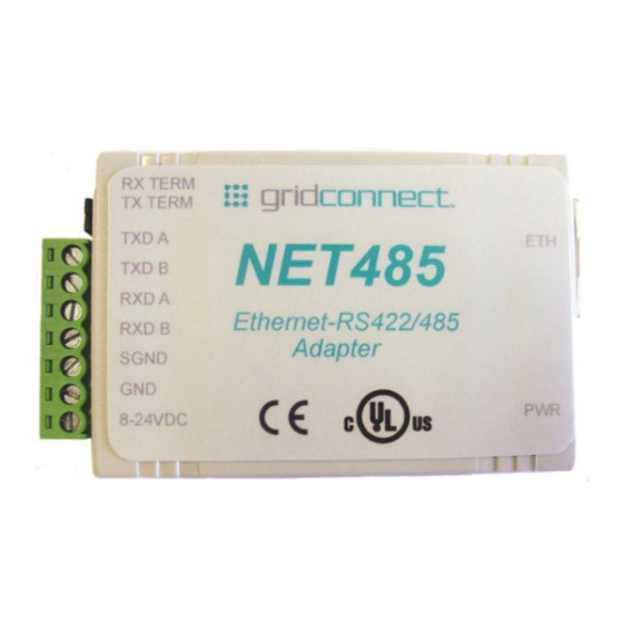
Page 1: Ethernet Adapter
NET485 RS422/485 Serial to Ethernet Adapter Revision E October 14, 2013... -
Page 3: Technical Support
Connect, Inc. All other product names, company names, logos or other designations mentioned herein are trademarks of their respective owners. NET485 is a trademark of Grid Connect, Inc. Warranty For details on the Grid Connect warranty policy, please go to our web site at http://gridconnect.com/customer-service/policies. - Page 4 Comments 05/17/05 Preliminary Release 06/23/05 Add notes about Product Info Base, Java RE, .NET 03/24/06 Firmware to 6.1.0.2 and Web Manager update 07/06/10 Remove Dev. Inst., add drawings. 10/14/13 UL and CE agency approvals. Support for xPort-05. NET485 User Guide...
-
Page 5: Table Of Contents
Contents Table of Contents 1. NET485 Overview ......................1-1 1.1 Overview ......................1-1 1.2 Overview of RS422 / RS485 ................1-1 1.2.1 The RS485 Enable Signal ..............1-2 1.2.2 RS422 Operation ................. 1-4 1.2.3 RS485 Operation ................. 1-5 1.3 RS422 / RS485 Network connections ..............1-6 1.3.1 RS422 Networks .................. - Page 6 3.10.11 Disable Port 77F0 (Hex) ............... 3-29 3.11 Defaults ......................3-29 Exit Configuration Mode ..................3-30 4. Monitoring the Network ....................4-1 4.1.1 Entering Monitor Mode via the Network Port ........4-1 4.1.2 Monitor Mode Commands ..............4-1 5. Updating Firmware ......................5-1 NET485 User Guide...
- Page 7 Figure 7 - J2 Setting for Half Duplex ..................2-3 Figure 8 - J2 Setting for Full Duplex ..................2-3 Figure 9 - Ethernet Jack ......................2-4 Figure 10 - Setup Mode Window ................... 3-7 Figure 11 - Hostlist Option ....................3-16 NET485 User Guide...
- Page 8 Contents List of Tables Table 1 - RS422/485 Signals ....................2-2 Table 2 - NET485 LED Functions ..................2-4 Table 3 - Technical Specs ...................... 2-6 Table 4 - Standard IP Network Netmasks ................3-8 Table 5 - Netmask Examples ....................3-9 Table 6 - Interface Mode Options ..................
-
Page 9: Net485 Overview
RS422/485 to Ethernet packets. You can now read RS422/485 data over Ethernet from anywhere in the world. Using RS485 two-wire mode, you can also connect the NET485’s serial interface to multiple devices in a multi-drop network. 1.2 Overview of RS422 / RS485 RS232 is an EIA standard transmission system and has been around since 1962. -
Page 10: The Rs485 Enable Signal
One of those options is the transmit enable, which is labeled “RS485 TX Enable”. The Quick Start Guide explains how to configure the NET485 for proper RS485 operation. WARNING: The NET485 comes from the factory already configured for RS485 operation. If you reset it to factory defaults, you will have to reconfigure the unit for RS422/485. - Page 11 Overview This version of the configurable pins window shows CP1-3. Web Manager 2.0.0.2. The NET485 uses Configurable Pin 1 (CP1) for the transmit enable. You must enable RS485_TXEN during the configuration process. (See the Quick Start Guide for details) The NET485 uses in the Active High condition.
-
Page 12: Rs422 Operation
Overview 1.2.2 RS422 Operation The NET485 can handle both RS485 and RS422 communications. This is done by connecting the processor (CPU) to a pair of RS485 transceivers. The following schematic demonstrates how the circuit is wired for RS422. For RS422 mode, use the four signals produced by the two transceivers plus a signal ground as shown in Figure 1 –... -
Page 13: Rs485 Operation
RXDB terminal. The three signals are TXDA, RXDB, and signal ground. 3.3V 3.3V RS485 Mode RS485 Mode TXDA (Pin 7) TXDB (Pin 6) 3.3V 3.3V 3.3V RXDA (Pin 5) RXDB (Pin 4) SGND (Pin 3) TXDA TXDB SGND Figure 2 - RS485 Wiring NET485 User Guide... -
Page 14: Rs422 / Rs485 Network Connections
A and B lines. Rg is an optional resistor between ground and the shield. Rt termination resistors are available as option jumpers on the NET485. Note: Do NOT install termination resistors on short wire networks. See the Application Notes on the product CD for more information about networks and termination procedures. -
Page 15: Rs485 Networks
Note: Do NOT install termination resistors on short wire networks. See the Application Notes on the product CD for more information about networks and termination procedures. SGND (Pin 3) SGND TXDA TXDA (Pin 7) TXDB (Pin 6) RXDA (Pin 5) RXDB RXDB (Pin 4) SGND TXDA RXDB Figure 4 - RS485 Network NET485 User Guide... -
Page 17: Introduction
4000 feet. The NET485 allows you to connect an RS422/485 device to the Internet so that you can connect to the device from anywhere there is an Internet connection. Many industrial computers have an RS422/485 interface to connect to their control systems. -
Page 18: Protocol Support
2.3 Serial RS422/485 Interface The table below lists the RS422/485 signals for the NET485. The RS422/485 and power interface is a 7-pin removable Phoenix connector, with two of the pins used for power. -
Page 19: Full Duplex-Half Duplex Jumper
2.4 Full Duplex-Half Duplex Jumper The NET485 is factory set for RS485. You can change it to RS422 by changing the protocol for the port setting. See Channel 1 Configuration on page 3-3. You can select Full or Half Duplex by changing the internal jumper J2. -
Page 20: Ethernet Interface
The CD sent with the NET485 contains software and technical manuals to support the NET485. Device Installer is one of the main software utilities that allows for fast and easy configuration of the NET485. 1. Insert the CD into your CD-ROM drive. The CD will automatically start and display the main window. -
Page 21: Additional Documentation
Introduction 2.8 Additional Documentation The following guides are available on the product CD. There are several other manuals on the CD, however, they do not apply to the NET485 product. Title Description File Name This manual in PDF format. NET485_UM.pdf... -
Page 22: Technical Specifications
2.9 Technical Specifications Table 3 - Technical Specs The transceiver used in the NET485 is intended for balanced data transmission and complies with both EIA Standards RS-485 and RS-422. It contains a differential line driver and a differential line receiver, and is suitable for half-duplex transfer. -
Page 23: Getting Started
Device Installer 3. Getting Started This chapter covers the required steps to get the NET485 Serial to Ethernet adapter on-line and working. The NET485 contains a complete device server that controls the network communications. Note: See the Quick Start Guide for a quick setup procedure. -
Page 24: Methods Of Assigning The Ip Address
Hardware Address: 00-20-4a- ____ - ____ - ____ 3.3.2 IP Address Your NET485 must have a unique IP address on your network. The systems administrator generally provides the IP address and corresponding subnet mask and gateway. The IP address must be within a valid range, unique to your network, and in the same subnet as your PC. -
Page 25: Autoip
Device Installer is a Windows-based utility for configuring embedded device servers found in products such as the NET232, NET232jr and NET485 Serial to Ethernet adapters. Device Installer supports several functions such as setting network parameters, pinging a network device, and changing baud rate. The first operation you must do is to locate the device on your network and assign the device a fixed IP address. -
Page 26: Configurable Pin Settings
4. On the main menu, click Apply Settings. 3.4.2 Configurable Pin Settings There are three configurable hardware pins on the NET485. See the notes in The RS485 Enable Signal on page 1-2. To configure the NET485 for RS485 Tx Enable: 1. -
Page 27: Configuration Using Telnet
1. From the Windows Start menu, click Run and type the following command, where x.x.x.x is the IP address and 9999 is the unit’s fixed network configuration port number. telnet x.x.x.x 9999 Note: Be sure to include a space between the IP address and 9999. 2. Click OK. NET485 User Guide... -
Page 28: Telnet Messages
CPU performance : Regular Monitor Mode @ bootup : enabled RS485 tx enable : active low (Should be set to high for NET485) HTTP Port Number : 80 SMTP Port Number : 25 MTU Size: 1400 TCP Re-transmission timeout: 500 ms... -
Page 29: Figure 10 - Setup Mode Window
Re-notification interval : 0 s Change Setup: 0 Server 1 Channel 1 3 E-mail 5 Expert 6 Security 7 Defaults 8 Exit without save 9 Save and exit Your choice ? Figure 10 - Setup Mode Window NET485 User Guide... -
Page 30: Server Configuration (Option 0 Network Configuration)
The unit prompts for the number of host bits to be entered, then calculates the netmask, which is displayed in standard decimal-dot notation when the saved parameters display (for example, 255.255.255.0). Table 4 - Standard IP Network Netmasks Network Class Host Bits Netmask 255.0.0.0 255.255.0.0 255.255.255.0 NET485 User Guide... -
Page 31: Set Dns Server Ip Address
Setting the Telnet configuration password prevents unauthorized access of the setup menu via a Telnet connection to port 9999 or through Web pages. The password is limited to 4 characters. An enhanced password setting of 16 characters is available under Security Settings for Telnet access only. NET485 User Guide... -
Page 32: Dhcp Naming
0.0.0.0, then the last option in "Server configuration" will be "Change DHCP device name". The "Change DHCP device name" option will allow you to change the DHCP name to an alpha-numeric name. Change DHCP device name (not set) ? (N) Y Enter new DHCP device name : LTX 3-10 NET485 User Guide... -
Page 33: Enable Dhcp Fqdn Option
Valid baud rates are 300, 600, 1200, 2400, 4800, 9600 (default), 19200, 38400, 57600, 115200, and 230400 bits per second. XPort-03 and greater units also support high-performance baud rates of 460800 and 921600 bps. NET485 User Guide 3-11... -
Page 34: I/F (Interface) Mode
Flow control sets the local handshaking method for stopping serial input/output. Table 8 - Flow Control Options Flow Control Option No flow control XON/XOFF flow control Hardware handshake with RTS/CTS lines (see note) XON/XOFF pass characters to host 3-12 NET485 User Guide... -
Page 35: Port Number
The automatic port increment feature must only be used when this device is the one initiating a connection using TCP. The port must be set to a non-zero value when this is a passive device or when UDP is being used instead of TCP. NET485 User Guide 3-13... -
Page 36: Connect Mode
With a specific start character Manual connection Autostart Hostlist Datagram Type Directed UDP Modem Mode No Echo Data Echo and Modem Response (Numeric) Data Echo and Modem Response (Verbose) Modem Response Only (Numeric) Modem Response Only (Verbose) 3-14 NET485 User Guide... - Page 37 129.1.2.3, then an example command string would be C3/7. (This would connect to 129.1.2.3 and port 7.) You may also use a different ending for the connection string. For example, C50.1/23 would connect you to 129.1.50.1 and port 23. NET485 User Guide 3-15...
-
Page 38: Figure 11 - Hostlist Option
(00) Figure 11 - Hostlist Option To use the Hostlist option, follow these steps: 1. Enter a Connect Mode of 0x20 (2X). The menu shows you a list of current entries already defined in the product. 3-16 NET485 User Guide... - Page 39 Note: If the unit is in Modem Mode and the serial port is idle, the unit can still accept network TCP connections to the serial port if Connect Mode is set to 06 (no echo), 16 (echo with full verbose), or 17 (echo with 1-character response). NET485 User Guide 3-17...
- Page 40 When an active connection is in effect, the unit will terminate the connection if the following sequence is received from the attached serial device: 1. No serial data is received for one second. 2. The character sequence +++ is received, with no more than one second between each two characters. 3-18 NET485 User Guide...
-
Page 41: Send The Escape Sequence (+++) In Modem Mode
Disable or enable the ability to send the escape sequence. The default is Y (Yes) (send the escape sequence). 3.7.7 Show IP Address after ‘RING’ The ability to enable or disable the display of the remote IP address in modem mode. Not used with NET485. NET485 User Guide 3-19... -
Page 42: Auto Increment Source Port
State LED off with connection Disconnect with EOT (^D) 1. The NET485 will send the "Terminal Type" upon an outgoing connection. 2. A password is required for a connection to the serial port from the network. 3. The TCP connection will close even if the remote site does not acknowledge the disconnection. -
Page 43: Flush Mode (Buffer Flushing)
Clear with a connection that is initiated from the device to the network Clear with a connection initiated from the network to the device Clear when the network connection to or from the device is disconnected Alternate Packing Algorithm (Pack Control) Enable NET485 User Guide 3-21... -
Page 44: Pack Control
Enter time in the following format: mm:ss, where m is the number of minutes and s is the number of seconds. To disable the inactivity timeout, enter 00:00. Range is 0 (disabled) to 5999 seconds (99 minutes, 59 seconds). Default setting is 0. 3-22 NET485 User Guide... -
Page 45: Send Characters
Configurable Pins and are designated CP1, CP2, and CP3 in the Web Manager. In order to use the E-mail function on the XPort, you will need access to the configurable pins. The NET485 limits the access so you cannot use the configurable pins to trigger an E-mail message. Your only option is to use a two-byte serial string to initiate a trigger. -
Page 46: E-Mail Setup
E-mail setup requires you to set up the e-mail server location as follows: Mail server: The IP address in decimal-dot notation. Unit: The user name used by the NET485 to send e-mail messages Domain: The Domain name of your e-mail server Recipient 1: Full e-mail address of the recipient. -
Page 47: Tcp Keepalive Time In Seconds
Monitor Mode except thru 'xxx' followed by 'M'. All other Monitor Mode entry sequences, e.g. 'zzz' and 'yyy', are blocked during startup. Note: Since the NET485 is not capable of Monitor Mode at Bootup, this option is not used. 3.9.5 RS-485 TX Enable Active Level This option allows the selection of the active level (either active high or active low) for the RS485_TXEN signal. -
Page 48: Smtp Port Number
If necessary, enable the alternate MAC address (if specified in the OEM setup record). 3.9.11 Ethernet Connection Type The NET485 allows for the Ethernet speed and duplex to be manually configured. Enter 0 for auto- negotiation (default). To select the speed and duplex, enter one of the following: 2 (10Mbit/half duplex), 3 (10Mbit/full duplex), 4 (100Mbit/half duplex), or 5 (100Mbit/full duplex). -
Page 49: Security Settings
Disable Port 77FEh (N) Disable Web Server (N) Disable Web Setup (N) Disable ECHO ports (Y) Enable Encryption (N) (Only if Encrypted NET485) Enable Enhanced Password (N) Disable Port 77F0h (N) 3.10.1 Disable SNMP This setting allows you to disable the SNMP protocol on the unit for security reasons. -
Page 50: Disable Web Server
192-, and 256-bit encryption key lengths. Note: Configuring encryption should be done through a local connection to the serial port of the NET485, or via a secured network connection. Initial configuration information, including the encryption key, is sent in clear text over the network. -
Page 51: Enable Enhanced Password
The specific settings that this option changes are listed below: Note: If you use default settings, the NET485 will not work properly. You must change the serial port setting for the NET485. See I/F (Interface) Mode on page 3-12. -
Page 52: Exit Configuration Mode
Exit Configuration Mode Select 8 to exit the configuration mode without saving any changes or rebooting. Select 9 to save all changes and reboot the device. All values are stored in nonvolatile memory. 3-30 NET485 User Guide... -
Page 53: Monitoring The Network
Note: Entering any of the commands listed above generates one of the following command response codes: Command Response Codes Response Meaning 0> OK; no error 1> No answer from remote device 2> Cannot reach remote device or no answer 8> Wrong parameter(s) 9> Invalid command NET485 User Guide... -
Page 55: Updating Firmware
3. Select the desired unit and click the Upgrade icon or select Upgrade from the Device menu. The Device Upgrade Wizard appears. Follow the instructions on the wizard screens. The unit performs a power reset after the firmware has been loaded and stored. NET485 User Guide... -
Page 57: Troubleshooting
NOTE: You cannot configure the NET485 through the serial port. The boot program has no control over the Configurable Pins, so the NET485 will never be able to send data during the boot period (initial 5 seconds). Note: Some unexplained errors might be caused by duplicate IP addresses on the network. Make sure that your unit's IP address is unique. - Page 58 Setup Mode via the serial port is NOT mode on the device server via NOT supported on the NET485 supported on the NET485. The unit is the serial port, you get no able to receive data but it cannot response.
-
Page 59: Binary To Hex Conversion
Another simple way to convert binary to hexadecimals is to use a scientific calculator, such as the one available on Windows’ operating systems. For example: 1. On the Windows’ Start menu, click Programs/Accessories/Calculator. 2. On the View menu, select Scientific. The scientific calculator displays. 3. Click Bin (Binary), and type the number to convert. NET485 User Guide... - Page 60 Tables Click Hex. The hexadecimal value displays. NET485 User Guide...
-
Page 61: Agency Approvals
Tables 8. Agency Approvals Revised label for CE and UL marks. For UL marks, see the online database at www.ul.com/database additional information. NET485 User Guide... -
Page 62: Certificate Of Compliance
Tables 8.1 Certificate of Compliance NET485 User Guide... -
Page 63: Electromagnetic Compatibility Tests
Tables 8.2 Electromagnetic Compatibility Tests Purpose: This test series was performed to determine if the NET485 would meet selected requirements of the IEC 61000-6-1 and IEC 61000-6-3 specifications. Deviations, Additions and Exclusions: There were no deviations, additions to, or exclusions from the test specification during this test series.
Need help?
Do you have a question about the NET485 and is the answer not in the manual?
Questions and answers