Table of Contents
Advertisement
Advertisement
Table of Contents

Subscribe to Our Youtube Channel
Related Manuals for GridConnect CAN USB-232


Summary of Contents for GridConnect CAN USB-232
- Page 1 CAN USB-232 User Manual Revision E August 1, 2016...
- Page 3 Grid Connect and the Grid Connect logo, and combinations thereof are registered trademarks of Grid Connect, Inc. All other product names, company names, logos or other designations mentioned herein are trademarks of their respective owners. CAN USB-232 is a trademark of Grid Connect, Inc. Grid Connect 1630 W. Diehl Rd.
- Page 4 Date Rev. Author Comments 04/19/2012 Preliminary Release 10/15/12 Updates to drawings 11/27/12 GR/DQ New Features. V01.02 05/14/2015 GR/DQ 16-bit Timestamp for received messages 08/01/2016 GR/JK Power input specifications CAN USB-232 User Manual...
- Page 5 The contents of this document shall not become part of or modify any prior or existing agreement, commitment or relationship. CAN USB-232 User Manual...
-
Page 6: Table Of Contents
2.6.4 Set CAN Port Baud Sample Point ............. 2-21 2.6.5 Set CAN Port Baud Sample Point Tolerance ........2-22 2.6.6 Set CAN Port Baud Sample Point Browse ........2-22 2.6.7 Set CAN Port Baud Sample Point Tolerance ........2-23 CAN USB-232 User Manual... - Page 7 2.12.1 get timestamp ................... 2-49 2.12.2 set timestamp ................... 2-50 2.13 CAN Timeout Commands ................2-50 2.13.1 Get can timeout ................2-50 2.13.2 Set can timeout can_tx_busy=timeout ..........2-50 2.14 Serial Number in Command Mode ..............2-51 CAN USB-232 User Manual...
- Page 8 2.17.1 Cycling LED Indicators ..............2-55 2.17.2 Generating CAN Square Wave ............2-55 2.17.3 Test LEDs ..................2-55 2.17.4 Test LEDs and CAN Bus ..............2-55 2.17.5 Exit ....................2-55 2.18 XMODEM Download ..................2-56 2.19 Technical Support ................... 2-56 CAN USB-232 User Manual...
-
Page 9: Overview
COM port to send and receive CAN messages on an ISO11898 CAN network. The CAN USB-232 can be configured to operate in either the command mode or the virtual circuit mode, providing the user with a choice as to the type of functionality desired. - Page 10 To protect against unauthorized duplication of hardware, the firmware is encrypted with a 256-bit AES cipher. The boot loader decrypts and verifies authenticity of the firmware to ensure only an authorized version is being downloaded. CAN USB-232 User Manual...
-
Page 11: Hardware Description
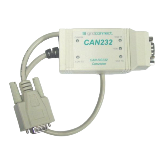
There are two hardware platforms, both of which execute the same firmware, with one providing a CAN- RS232 interface and the other a CAN-USB interface. The CAN-RS232 platform has the option of DTE (male) or DCE(female) on the RS232 serial cable, and the option of a Male or Female DB9 CAN connector. CAN USB-232 User Manual... -
Page 12: Can Network
1.4 CAN Network Before trying to send commands to the CAN USB-232, make sure the unit is attached to a valid CAN network with at least one other node attached and running. Without another node on the network, the CAN USB-232 will attempt to transmit the message indefinitely (as per CAN 2.0A/B specifications). -
Page 13: Additional Documentation
Getting Started 1.5 Additional Documentation This manual provides basic information about the CAN USB-232 installation and operation. For specific details about configuration and operation, please see the following manuals. The following documents are available on the product CD. Title Description... -
Page 14: Getting Started
Figure 1 - CD Main Window 1. Click on an item for more information. 2. Click the Browse CD button to view the contents of the CD. 3. Click the Go to Software Page button to view software options. CAN USB-232 User Manual... -
Page 15: Teraterm Install
Windows Server 2003, Windows Vista, Windows Server 2008, Windows 7, Windows Server 2008 R2. Please read the Windows application note: AN_104_FTDI_Drivers_Installation_Guide_for_WindowsXP(FT_000093).pdf. Please read the Windows 7 application note: AN_119_FTDI_Drivers_Installation_Guide_for_Windows7.pdf. The application notes and the driver files are contained on the software CD in the Windows folder. CAN USB-232 User Manual... -
Page 16: Com Port Assignment
USBView is a free utility from Microsoft that displays the USB connection tree and shows the USB devices that are connected to it together with their configuration data. This is very useful for debugging USB enumeration errors. USBView runs under Windows 98, ME, 2000 and XP. CAN USB-232 User Manual... -
Page 17: Hardware Installation
NOT connected to the DB9-Male cable at the factory. If you need the push button input, contact the sales department to get a quote for a custom cable. DB9-Male DTE +7-24 VDC XCFG PB DB9-Female DCE +7-24 VDC XCFG PB CAN USB-232 User Manual... -
Page 18: Usb Cable Wiring
The Jumper J8 should be in position 3-2 for Phoenix or barrel jack power. Jumper J8 should be in position 1-2 for serial cable or OEM (J10) supplied power. Factory default setting is a jumper in position 3-2. 2-10 CAN USB-232 User Manual... -
Page 19: Item Locator Can-232
2.2.5 Item Locator CAN-USB 2.2.6 Input Power The input power range is from 7-24VDC for the CAN-232 model. The 5V regulator U5 supplies power to the U6, the 3.3V regulator. D8 is the Power LED. CAN USB-232 User Manual 2-11... -
Page 20: Isolated Power Option
The RS232 signals are brought out to the OEM connector at J10. Power can be supplied through pin 1 and Ground is tied to pin 9. J8 must also be jumpered between pins 1 and 2. (See Power Options for J8) 2-12 CAN USB-232 User Manual... -
Page 21: Configuration Push Button
Pressing the recessed push button for less than 3 seconds will put the processor into configuration mode. Pressing the recessed push button for MORE than 3 seconds will reset the unit to factory defaults. See the Configuration chapter for detailed operation. CAN USB-232 User Manual 2-13... -
Page 22: Can Driver
IEC 60747-5-2 (VDE 0884, Rev. 2) & IEC 61010-1 Approved UL 1577 Double Protection Approved IEC 60601-1 (Medical) and CSA Approved 5 KVRMS Reinforced Insulation per TUV Approved for EN/UL/CSA 60950-1 (ISO1050DW) Typical 25-Year Life at Rated Working Voltage 2-14 CAN USB-232 User Manual... -
Page 23: Ttl Option
This CAN-232 model option allows a user to connect TTL level signals to the board through the serial port cable. U4, the TTL to RS232 converter, is removed and the resistor pack, RP4 is installed. U8 is also installed for protection. This option is by special order and NOT a field option. CAN USB-232 User Manual 2-15... -
Page 24: Entering Configuration Mode
USB Serial Port. To view the Configuration menu, first connect the CAN-USB cable to a PC running a monitor program, such as Terra Term. Set the COM port parameters to 115200, 8, 1, None. 2-16 CAN USB-232 User Manual... -
Page 25: Config Button
Getting Started 2.3.3 Config Button Press the Config button (for less than 3 seconds) located next to the cable. The config prompt should appear as #0#. Type help or ? to display the prompt messages. CAN USB-232 User Manual 2-17... - Page 26 To get help with a specific item, type help xx, where xx is the number in the left column next to each menu item. The commands are detailed in the same sequence as they appear in the following menu. 2-18 CAN USB-232 User Manual...
-
Page 27: Mode Options
2.4 Mode Options 2.4.1 Get Mode In the command mode (CM), the CAN USB-232 is capable of sending and receiving arbitrary CAN messages via the use of ASCII formatted message strings. In virtual circuit mode (VC), the CAN USB-232 establishes a full-duplex, virtual circuit between itself and another CAN USB-232 or application device. -
Page 28: Set Com Port
2.6.2 CAN Bus State During Configuration While the CAN USB-232 is in the configuration mode, the CAN controller is in the bus-off state. It does not interact with the bus and is effectively ‘invisible’. Thus, it is possible to perform configuration of the CAN USB-232 while still connected to an active CAN network and not adversely affect network operation. -
Page 29: Get Can Port
Getting Started 2.6.3 Get CAN Port 2.6.4 Set CAN Port Baud Sample Point CAN USB-232 User Manual 2-21... -
Page 30: Set Can Port Baud Sample Point Tolerance
Troubleshooting 2.6.5 Set CAN Port Baud Sample Point Tolerance 2.6.6 Set CAN Port Baud Sample Point Browse 2-22 CAN USB-232 User Manual... -
Page 31: Set Can Port Baud Sample Point Tolerance
The ‘TSEG1’ parameter determines the amount of time to wait before the hardware attempts to sample the bit. The value can range from 1 to 16. The ‘TSEG2’ parameter determines the amount of time remaining before the end of the bit. The value can range from 1 to 8. CAN USB-232 User Manual 2-23... -
Page 32: Can Command Mode
CAN node to adjust its sampling point when it determines that the sample point would be too early or too late. By setting the SJW field to a large number, the CAN USB-232 can work with other nodes with a large variation is bus oscillator tolerances. -
Page 33: Message String Syntax
Normal CAN Message Syntax : <S | X> <IDENTIFIER> <N> <DATA-0> <DATA-1> … <DATA-7> ; The first character,‘:’, is for synchronization and allows the CAN USB-232 parser to detect the beginning of a command string. The following character is either ‘S’ for standard 11-bit, or ‘X’ for extended 29-bit identifier type. -
Page 34: Rtr Can Message
2.7.4 Appending CR/LF To Received Command Strings When using the CAN USB-232 to view received CAN messages directly on a terminal, the user can set a configuration parameter to append a <CR> <LF> sequence to each message string generated. This makes it easier for the user to see each received message as each message will be on a separate line. -
Page 35: Binary Formatted Messages
Getting Started 2.7.5 Binary Formatted Messages The tables below show the format for Binary message format. CAN USB-232 User Manual 2-27... - Page 36 Troubleshooting 2-28 CAN USB-232 User Manual...
-
Page 37: Get Can Command Mode Settings
Getting Started 2.7.6 Get CAN Command Mode Settings 2.7.7 Set CAN Command Mode Filter On/Off CAN USB-232 User Manual 2-29... -
Page 38: Set Can Command Mode Rx Operating Mode
Troubleshooting 2.7.8 Set CAN Command Mode RX Operating Mode 2.7.9 Set CAN Command Mode RX Input Format 2.7.10 Set CAN Command Mode TX Output Format 2-30 CAN USB-232 User Manual... -
Page 39: Set Can Command Mode Message Output Termination
The CAN USB-232 only sends CAN messages when eight bytes of data have been received. This leads to a case where the last part of a data stream is not sent if it is less than eight bytes long. To deal with this in a transparent fashion, the CAN USB-232 provides a timeout feature that will automatically force a transmission of the last accumulated byte(s) after a specified maximum waiting time. -
Page 40: The 'Xmit' And 'Rcev' Identifiers
When a CAN message containing this identifier is received, the data in the message is assumed to be stream data from another CAN USB-232. This data is then read and output directly to the serial COM port of the receiving CAN USB-232 unit, providing the completion of the virtual circuit. -
Page 41: Get Can Virtual Circuit Setting
Getting Started 2.8.4 Get CAN Virtual Circuit Setting CAN USB-232 User Manual 2-33... -
Page 42: Set Can Virtual Circuit Tx Id
Troubleshooting 2.8.5 Set CAN Virtual Circuit TX ID 2-34 CAN USB-232 User Manual... -
Page 43: Set Can Virtual Circuit Rx Id
Getting Started 2.8.6 Set CAN Virtual Circuit RX ID CAN USB-232 User Manual 2-35... -
Page 44: Set Can Virtual Circuit Forced Send Code
Troubleshooting 2.8.7 Set CAN Virtual Circuit Forced Send Code 2-36 CAN USB-232 User Manual... -
Page 45: Set Can Virtual Circuit Forced Wake Code
Getting Started 2.8.8 Set CAN Virtual Circuit Forced Wake Code CAN USB-232 User Manual 2-37... -
Page 46: Set Can Virtual Circuit Timeout Send
Troubleshooting 2.8.9 Set CAN Virtual Circuit Timeout Send 2-38 CAN USB-232 User Manual... -
Page 47: Set Can Virtual Circuit Wake Timeout
Getting Started 2.8.10 Set CAN Virtual Circuit Wake Timeout CAN USB-232 User Manual 2-39... -
Page 48: Set Can Virtual Circuit Wait After Wakeup
Troubleshooting 2.8.11 Set CAN Virtual Circuit Wait after Wakeup 2-40 CAN USB-232 User Manual... -
Page 49: Set Can Virtual Circuit Wakeup Message
CONFIG command is enabled, should the config command sequence match one of the force codes, it will be treated as a config command character. To avoid this, either change the force codes or change the config command sequence. CAN USB-232 User Manual 2-41... -
Page 50: Defining Filter Entries
2.10.1 How Filtering Works Whenever the CAN USB-232 receives a CAN message from the network, it checks to see if any filters are enabled. If none of the filters are enabled, it assumes no filtering should be performed and outputs the ASCII message string of the message to the serial port. -
Page 51: Setting Up Message Filters
2) Specify if standard or extended and if single ID or ID range. Once all configuration parameters have been saved and the CAN USB-232 enters the normal operating mode, the new filter settings will become active and will be applied to each received CAN message. -
Page 52: Set Can Filter
2.10.5 Delete CAN Filter Either a single entry or and entry range can be specified. Entries are identified by their index number. Indexes remaining are re-sorted so there are no gaps. EX-1: del can filter 1 2-44 CAN USB-232 User Manual... -
Page 53: Delete Can Filter Range
Getting Started 2.10.6 Delete CAN Filter Range 2.10.7 Delete CAN Filter All CAN USB-232 User Manual 2-45... -
Page 54: Config Entry Commands
CM Mode: get cfgcmd cm: Returns the current state of the CM mode config command set cfgcmd cm enabled=yes | no: Enables or disables the command in CM mode (default is enabled) 2-46 CAN USB-232 User Manual... -
Page 55: Get Cfgcmd Cm
: " (double quote) : BACKSLASH Ex 1 : "\000" : Binary 0x00 Ex 2 : "\r\n" " CR followed by LF 2.11.1 Get cfgcmd cm 2.11.2 Set cfgcmd cm enable=YES | NO 2.11.3 Get cfgcmd vc CAN USB-232 User Manual 2-47... -
Page 56: Set Cfgcmd Vc Enable=Yes | No
2.12 CAN Timestamp Commands Received CAN messages can now have a 16-bit time-stamp appended to them with a 1-ms resolution. For backward compatibility, this feature is disabled by default and can be enabled by a configuration command. 2-48 CAN USB-232 User Manual... -
Page 57: Get Timestamp
The time-stamp field is always two logical bytes, but can be expanded up to four in the case where both MSB and LSB bytes are synchronization characters. 2.12.1 get timestamp CAN USB-232 User Manual 2-49... -
Page 58: Set Timestamp
Gets the timeout setting. set can timeout can_tx_busy=off: Disables timeout, will wait indefinitely (default) set can timeout can_tx_busy=1000: Sets the timeout (10 to 10000 ms) 2.13.1 Get can timeout 2.13.2 Set can timeout can_tx_busy=timeout 2-50 CAN USB-232 User Manual... -
Page 59: Serial Number In Command Mode
Three units are configured to have the same RX identifier in RTR mode. Each units as unique TX identifiers. When a node on the network issues a RX identifier request for serial numbers, the three units will all transmit their respective serial number messages. CAN USB-232 User Manual 2-51... -
Page 60: Profiles
Sets the profile note for the current profile to "Text" (default "") profile note #="Text": Sets the specified profile note to "Text" (0 to 9) 2.15.1 Set Active Profile Number 2.15.2 Copy Profile 2-52 CAN USB-232 User Manual... -
Page 61: Profile Note
: Returns the nore for the specified profile number (0 to 9) 2.15.5 Profile Note All profile note all : Returns a list of all profile notes. 2.15.6 Profile Note Text profile note="Text" : Sets the profile note for the current profile to "Text" (default "") CAN USB-232 User Manual 2-53... -
Page 62: Set Active Profile To Default
2.16 Serial Number in Config Mode 2.16.1 CAN Port SERNUM Interaction The SERNUM command provides a means for the user to query the CAN USB-232 for its unique 128-bit serial number. The GET SERNUM command only works while in CONFIG mode and always returns the serial number over the COM port. -
Page 63: Get Version Number
2.17.2 Generating CAN Square Wave The CAN USB-232 can generate a square wave output onto the CAN bus arbitrary frequencies. It is useful for measuring propagation delay through cabling with the aid of an oscilloscope and can be used to evaluate bus termination. -
Page 64: Xmodem Download
CD. If you are unable to solve the problem, please contact technical support. Grid Connect technical support: (630) 245-1445. Our phone lines are open from 8:00AM - 4:30 PM Central Time Monday through Friday excluding holidays. 2-56 CAN USB-232 User Manual... - Page 65 CAN USB-232 User Manual...
Need help?
Do you have a question about the CAN USB-232 and is the answer not in the manual?
Questions and answers