JVC KV-M705 Service Manual
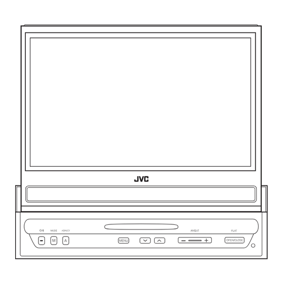
In-dash 7-inch widescreen monitor
Hide thumbs
Also See for KV-M705:
- Instructions manual (7 pages) ,
- Installation & connection manual (4 pages) ,
- Installation and connection manual (4 pages)
Advertisement
SERVICE MANUAL
IN-DASH 7-INCH WIDESCREEN MONITOR
2005
10
MA209
KV-M705,KV-M706
Lead free solder used in the board (material : Sn-Ag-Cu, melting point : 219 Centigrade)
1
PRECAUTION. . . . . . . . . . . . . . . . . . . . . . . . . . . . . . . . . . . . . . . . . . . . . . . . . . . . . . . . . . . . . . . . . . . . . . . . . 1-3
2
SPECIFIC SERVICE INSTRUCTIONS . . . . . . . . . . . . . . . . . . . . . . . . . . . . . . . . . . . . . . . . . . . . . . . . . . . . . . 1-3
3
DISASSEMBLY . . . . . . . . . . . . . . . . . . . . . . . . . . . . . . . . . . . . . . . . . . . . . . . . . . . . . . . . . . . . . . . . . . . . . . . 1-4
4
ADJUSTMENT . . . . . . . . . . . . . . . . . . . . . . . . . . . . . . . . . . . . . . . . . . . . . . . . . . . . . . . . . . . . . . . . . . . . . . . 1-10
5
TROUBLESHOOTING . . . . . . . . . . . . . . . . . . . . . . . . . . . . . . . . . . . . . . . . . . . . . . . . . . . . . . . . . . . . . . . . . 1-14
TABLE OF CONTENTS
COPYRIGHT © 2005 Victor Company of Japan, Limited
KV-M705
Area suffix
E ------------- Southern Europe
UT ------------------------- Taiwan
UN --------------------- Indonesia
HUN ------------------ Indonesia
U -------------------- Other Areas
KV-M706
Area suffix
J ------------- Northern America
E ------------- Southern Europe
UT ------------------------- Taiwan
UN --------------------- Indonesia
U -------------------- Other Areas
No.MA209
2005/10
Advertisement
Table of Contents

Related Manuals for JVC KV-M705


Summary of Contents for JVC KV-M705
-
Page 1: Table Of Contents
SERVICE MANUAL IN-DASH 7-INCH WIDESCREEN MONITOR MA209 2005 KV-M705,KV-M706 KV-M705 Area suffix E ------------- Southern Europe UT ------------------------- Taiwan UN --------------------- Indonesia HUN ------------------ Indonesia U -------------------- Other Areas KV-M706 Area suffix J ------------- Northern America E ------------- Southern Europe... - Page 2 SPECIFICATION Screen 7 inch liquid crystal panel 336 960 pixels (480 vertical × 234 horizontal × 3) Number of pixel Drive method TFT (Thin Film Transistor) active matrix format Color system NTSC/PAL RCA pin × 2 circuits 1 V(p-p), 75 Ω Input Video RCA pin ×...
-
Page 3: Precaution
SECTION 1 PRECAUTION Safety Precautions Burrs formed during molding may be left over on some parts of the chassis. Therefore, pay attention to such burrs in the case of preforming repair of this system. SECTION 2 SPECIFIC SERVICE INSTRUCTIONS This service manual does not describe SPECIFIC SERVICE INSTRUCTIONS. (No.MA209)1-3... -
Page 4: Disassembly
SECTION 3 DISASSEMBLY Main body section 3.1.1 Removing the front assembly (See Figs.1 to 3) (1) From the both sides of the main body, remove the two screws A attaching the front assembly to the main body. (See Fig.1.) (2) From the bottom side of the main body, release the two claws a attaching the front assembly to the main body. - Page 5 3.1.2 Removing the top drive unit (See Figs.4 to 6) • Prior to performing the following procedure, remove the front Top drive unit assembly. (1) From the both sides of the main body, remove the four screws B attaching the top drive unit to the main body. (See Fig.4.) (2) From the back side of the main body, remove the three screws C attaching the top drive unit to the main body.
- Page 6 3.1.3 Removing the LCD assembly (See Figs.7 to 10) • Prior to performing the following procedures, remove the front assembly and top drive unit. (1) From the top side of the top drive unit, remove the three screws D attaching the LCD assembly to the top drive unit. (See Fig.7.) (2) From the bottom side of the top drive unit, remove the two screws E attaching the FPC guide and take out it.
- Page 7 3.1.4 Removing the display rear cover (See Fig.11) • Prior to performing the following procedures, remove the front assembly, top drive unit and LCD assembly. (1) From the back side of the LCD assembly, remove the three screws F attaching the display rear cover to the LCD as- sembly.
- Page 8 3.1.6 Removing the monitor board (See Fig.14) • Prior to performing the following procedures, remove the front Tape CN851 assembly, top drive unit, LCD assembly, display rear cover and display back panel. (1) From the back side of the LCD assembly, remove the three screws J attaching the monitor board to the LCD assembly.
- Page 9 3.1.9 Removing the system control board (See Fig.17) • Prior to performing the following procedures, remove the front assembly, top drive unit and rear bracket. CN351 System control board (1) From the top side of the bottom case assembly, remove the five screws M attaching the system control board to the bot- tom case assembly.
-
Page 10: Adjustment
SECTION 4 ADJUSTMENT Service mode 4.1.1 Standard conditions Power supply voltage:DC14.4V (11V to 16V) 4.1.2 Service mode setting procedure 1. Press the [POWER] button, and the display panel will come out and stand upright. 2. Press the [POWER], [ ] and [OPEN/CLOSE] buttons in this order, and keep them pressed for 3 seconds or more. -
Page 11: Gamma1
INFORMATION : Area / Region indication / Version indication selected with the [ ] or [ button on the main unit, INFORMATION KV-M705 and the service mode menu Version number of system micom and ROM collection is entered with the [MODE] SYS VER XXXX button on the main unit. - Page 12 Monitor Mecha Running mode This mode is not used for service. MONITOR MECHA RUNNING > RUNNING MODE-1 To exit running mode, press the [POWER] button for RUNNING MODE-2 more than 3 seconds. RUNNING MODE-3 Then service mode is finished. RUNNING MODE-4 RUNNING MODE-5 RUNNING MODE-6 DW/UP : SEL...
- Page 13 4.1.4 LCD adjustment LCD free run frequency adjustment (1) Set the main unit in a service mode. (2) Select "LCD SETTING" of the service mode. (3) Connect the frequency counter to TP708 and TP761 (GND) on the monitor board. (Not supplying a signal in the input.) (4) Select "DAC OUT"...
-
Page 14: Troubleshooting
SECTION 5 TROUBLESHOOTING Mechanism initialization Operate the mechanism initialization when replacing the top drive unit. 5.1.1 Operation procedure of mechanism initialization (1) Setup the service mode, and operate "INITIALIZE ALL". (Refer to "4.1.2 Service mode setting procedure" and "4.1.3 Operation procedures") (2) After the all data are initialized, press the [RESET] button of the main unit. - Page 15 8 PIN CORD DIAGRAM OR/WH Black White L.GN VI/WH Yellow Orange Violet Light Green L.GN VI/WH REVERSE REVERSE L.GN PARKING PARKING OR/WH ILLUMI POWER LEAD GROUND MEMORY POWER MEMORY LEAD BACKUP ACC Line Memory Backup Battery+ MEMORY Ground Illuminations Control PARKING Parking Brake REVERSE...
- Page 16 Victor Company of Japan, Limited AV & MULTIMEDIA COMPANY CAR ELECTRONICS CATEGORY 10-1,1chome,Ohwatari-machi,Maebashi-city,371-8543,Japan (No.MA209) Printed in Japan...
- Page 17 SCHEMATIC DIAGRAMS IN-DASH 7-INCH WIDESCREEN MONITOR KV-M705, KV-M706 CD-ROM No.SML200510 KV-M705 Area suffix E ------------- Southern Europe UT ------------------------- Taiwan UN --------------------- Indonesia HUN ------------------ Indonesia U -------------------- Other Areas KV-M706 Area suffix J ------------- Northern America E ------------- Southern Europe...
-
Page 18: Safety Precaution
Safety precaution Burrs formed during molding may be left over on some parts of the chassis. Therefore, pay attention to such burrs in the case of preforming repair of this system. - Page 19 < M E M O >...
-
Page 20: Block Diagram
Block diagram Monitor section Mecha ROUT, GOUT, BOUT STH1, STH2 VCOM STV1, STV2 CLK1 to CLK3 Q651 to Q654 COM_OUT VIDEO_IN OEV1 to OEV3 VCOM CPV, OEH HSYNCIN IC691 IC741 SYNC_OUT VDBIN VIDEO IN SYNC BUFF. BUFFER BLACK, POL IC601 C_VIDEO(+)_IN VIDEO IC761... -
Page 21: Front Section
Mecha section S3601 S361 VR351 SLIDE PULSE ANGLE SENSOR S3201 P3201 CLOSE SW ANGLE SW CLSW ANGSW CN332 CN331 HSW, PULSE ANGSENS IC301 SW+B, PWR IC312 REGULATOR IC331 MOTOR MVCNT MOTOR VOLTAGE DRIVER CNTL0, CNTL1, CNTL2 CN301 CN391 Main section PULSE, HSW, ANGSW, CLSW IC251 ANG_SENS, MO_PWR, MVCNTL... - Page 22 Standard schematic diagrams Main section L V A 1 0 6 1 9 - 1 CN351 QGF0534F1-13X R351 0 FP_REM REMOCON DGND R352 0 RESET R353 0 FPKEY0 FPKEY0 R358 R354 0 FPKEY1 FPKEY1 R356 0 OPEN/CLOSE OPEN/CLOSE ILL_B ILL_GND ILL10V R355 0 LED_CONT...
- Page 23 Q308 2SD601A/QR/-X C326 R323 Q307 UN2211-X IC302 Q305 RSQ035P03-W Q306 1 2 3 L303 PGND F391 TO_MONITOR C330 NMFZ018-1R5X-E C391 CN391 QGF0534F1-16X SYS14 Q309 R130 UN2211-X SYS14 R126 R131 100k 100k MO_CNTL0 CNTL0 R127 TP116 MO_CNTL1 NTSC/PAL R144 4.9V 5.0V CNTL1 NTSC/PAL MO_CNTL2...
- Page 24 Front section L V A 1 0 6 1 9 - 2 R E M O C O M I C 4 6 1 R P M 6 9 3 8 - V 4 R 4 1 9 Q 4 1 1 Q 4 1 2 R 4 4 4 1 0 k...
- Page 25 C N 4 7 1 Q G F 0 5 3 4 F 1 - 1 3 X G N D R 4 7 1 0 R E M O C O N C 4 7 1 0 . 1 G N D R 4 7 2 0 R E S E T...
- Page 26 Monitor section L V A 1 0 6 2 0 - 1 L907 L908 L909 IC901 MM3203AF-X R901 R902 R903 910k 100k TP902 L904 L905 L906 TP901 IC911 NJM78L12UA-X TP931 L902 L901 C905 C901 C902 1/25 10/25 10/25 D902 RSX201L-30-X TP903 IC921 MM1563DF-X...
- Page 27 F831 NMFZ018-2R5X-E NMFZ018-2R5X-E C831 NQR0450-001X Q841 BACK LIGHT 7.1V 7.1V 14.1V T851 IC801 14.1V CN851 NJM78L05UA-X IC811 QGA3501F1-02X QGA3501F1-02X R818 2.5V 12.5V OZ961ISN-X C811 0.01 R813 2.5V C812 UPA1890GR-9JG-X C853 CTIMR NDRB 10p/3k 0.5V 2.5V R814 C819 PDRA 100p D841 5.0V 2.0V C818...
- Page 28 Mecha section MOTOR DRIVER MOTOR VOLTA 1 1 . 4 V V C C 2 0 . 6 V 1 1 . 4 V O U T 1 V C C 1 0 . 2 V G N D I N 3 C N 3 1 1 Q G A 1 0 0 2 C 1 - 0 2 X G N D...
- Page 29 REGULATOR VOLTAGE I C 3 0 1 BA00CC0WFP I C 3 1 2 NJM2125F R 3 0 0 1 1 8 k D 3 0 0 1 T O M A I N RB160M-30 B O A R D 1 4 . 1 V S W + B C 3 0 0 6 C 3 0 0 1...
- Page 30 Printed circuit boards Main board Lead free solder used in the board (material : Sn-Ag-Cu, melting point : 219 Centigrade) Forward side R303 D302 D342 R326 R342 D341 C334 R348 Q301 R357 R345 Q341 C343 C310 C121 L301 Q343 BZ101 TP123 R156 D317...
- Page 31 Reverse side TPX193 TP378 TP377 TP375 CN372 TP373 TP374 TP372 TP371 TP370 C274 R284 C275 TP382 TP353 TP381 TP354 TP355 TP380 TP356 TP383 TP376 TP379 R352 R353 R354 R356 C209 C210 TP352 R385 R386 R387 TP319 R388 R395 R389 TP327 TP328 R396 TP334...
- Page 32 Monitor board Lead free solder used in the board (material : Sn-Ag-Cu, melting point : 219 Centigrade) Forward side D851 C854 Q842 C842 C844 C832 C833 T851 C834 Q841 C934 IC911 C835 C836 R901 R902 C903 F831 C824 R816 R903 C819 R814 R817...
- Page 33 Monitor board Lead free solder used in the board (material : Sn-Ag-Cu, melting point : 219 Centigrade) Reverse side 2-14...
- Page 34 Victor Company of Japan, Limited AV & MULTIMEDIA COMPANY CAR ELECTRONICS CATEGORY 10-1,1chome,Ohwatari-machi,Maebashi-city,371-8543,Japan Printed in Japan (No.MA209SCH)
-
Page 35: Parts List
PARTS LIST [ KV-M705 ] [ KV-M706 ] * All printed circuit boards and its assemblies are not available as service parts. KV-M705 Area suffix E ----------------- Southern Europe UT -----------------------------Taiwan UN ------------------------ Indonesia HUN----------------------- Indonesia U ----------------------- Other Areas... - Page 36 Exploded view of general assembly and parts list Block No. Monitor board...
- Page 37 System control board Front key board...
- Page 38 General Assembly Block No. [M][1][M][M] Symbol No. Part No. Part Name Description Local LV11150-001A TOP DRIVE UNIT LV34862-002A F.P.C.GUIDE LV44159-001A MINI SCREW (x2) LV44159-001A MINI SCREW (x4) LV11145-003A DISPLAY PANEL M705E,M705HUN,M705U,M705UN,M705UT LV11145-004A DISPLAY PANEL M706E,M706J,M706U,M706UN,M706UT LV36181-002A BLIND SHEET LV22124-002A DISP BACK PANEL LV43819-004A SPECAL SCREW...
- Page 39 <MEMO>...
-
Page 40: Electrical Parts List
Electrical parts list Main board Symbol No. Part No. Part Name Description Local Block No. [0][1] C116 NCF31CZ-104X C CAPACITOR 0.1uF 16V Z Symbol No. Part No. Part Name Description Local C117 NEAF1CM-476X E CAPACITOR 47uF 16V M C118 NCF31CZ-104X C CAPACITOR... - Page 41 Symbol No. Part No. Part Name Description Local Symbol No. Part No. Part Name Description Local C319 NCF31CZ-104X C CAPACITOR 0.1uF 16V Z R134 NRSA63J-223X MG RESISTOR 22kΩ 1/16W J C320 NCB31HK-103X C CAPACITOR 0.01uF 50V K R135 NRSA63J-473X MG RESISTOR 47kΩ...
- Page 42 Symbol No. Part No. Part Name Description Local Symbol No. Part No. Part Name Description Local R256 NRSA63J-104X MG RESISTOR 100kΩ 1/16W J R353 NRSA63J-0R0X MG RESISTOR 0Ω 1/16W J R257 NRSA63J-153X MG RESISTOR 15kΩ 1/16W J R354 NRSA63J-0R0X MG RESISTOR 0Ω...
- Page 43 Symbol No. Part No. Part Name Description Local Symbol No. Part No. Part Name Description Local S435 NSW0206-001X TACT SWITCH C606 NCB31CK-104X C CAPACITOR 0.1uF 16V K S441 NSW0206-001X TACT SWITCH C607 NCB31CK-224X C CAPACITOR 0.22uF 16V K S442 NSW0206-001X TACT SWITCH...
- Page 44 Symbol No. Part No. Part Name Description Local Symbol No. Part No. Part Name Description Local C784 NBE41AM-476X TA E CAPACITOR 47uF 10V M R514 NRSA63J-101X MG RESISTOR 100Ω 1/16W J C785 NCJ11EK-106X-R C CAPACITOR R521 NRSA63J-333X MG RESISTOR 33kΩ...
- Page 45 Symbol No. Part No. Part Name Description Local Symbol No. Part No. Part Name Description Local R727 NRSA63J-102X MG RESISTOR 1kΩ 1/16W J L783 NQL085J-470X COIL 47uH J R728 NRSA63J-102X MG RESISTOR 1kΩ 1/16W J L784 NQL085J-470X COIL 47uH J R729 NRSA63J-102X...
- Page 46 Packing materials and accessories parts list Block No. No additional / supplemental order of WARRANTY CARDs are available. KIT : A7 A8 A9 A10 A11 A12 A13 A1 A2 A3 A4 A5 A18 A19 A20 A21 3-12...
- Page 47 Packing and Accessories Block No. [M][3][M][M] Symbol No. Part No. Part Name Description Local LVT1483-001A INST BOOK ENG GER FRE DUT M705E,M706E LVT1484-001A INST BOOK ING SPA FRE M706J LVT1399-002A INST BOOK TUR ARA PER M705U,M706U LVT1399-003A INST BOOK ENG INA M705HUN,M705UN,M706UN LVT1399-001A...
Need help?
Do you have a question about the KV-M705 and is the answer not in the manual?
Questions and answers