Table of Contents
Advertisement
Advertisement
Table of Contents

Related Manuals for Megger LCR131


Summary of Contents for Megger LCR131
- Page 1 LCR131 Dual display meter User Manual...
- Page 2 LCR131 Parameters Measured L/C/R/D/Q Measuring Circuit Mode Inductance (L) –Defaults to series mode Capacitance/ Resistance (C/R) -Defaults to parallel mode Displays L/C/R: Maximum display 19999 D/Q: Maximum display 999 (Auto Range). Ranging Mode Auto & Manual Measuring Terminals 3 terminals with sockets...
- Page 3 LCR131 COMPONENT TESTER USER MANUAL...
-
Page 4: Table Of Contents
Table of Contents PAGE Safety Introduction Front Panel Illustration LCD Display Illustration How to Operate Operating Instructions Data Hold Static Recording Dissipation Factor / Quality Factor Test Frequency L/C/R function selector Relative Tolerance Auto/manual ranging Automatic Fuse Detection Parallel / Series Mode Calibration Auto Power Off/ Disable Auto Power Off Low Battery Indication... -
Page 5: Safety
Safety Read "SAFETY INFORMATION" before using this meter. NOTE This meter is a hand-held, battery-operated instrument for testing inductance, capacitance and resistance. If this device is damaged or has any parts missing, contact the retailer immediately. This manual contains information and warnings which must be followed to ensure safe operation as well as to ensure the meter remains in a safe condition. - Page 6 SAFETY INFORMATION To ensure that you use this device safely, follow the safety guidelines listed below: This meter is for indoor use, altitude up to 2,000 m. The warnings and precautions should be read and well understood before the instrument is used. Use this device only as specified in this manual;...
-
Page 7: Introduction
Introduction This 19,999-count L/C/R hand-held meter is a special microprocessor-controlled meter for measuring functions of inductance, capacitance and resistance. Extremely simple to operate, the instrument not only takes absolute parallel mode measurements, but is also capable of series mode measurement. The meter provides direct and accurate measurements of inductors, capacitors and resistors with different testing frequencies. -
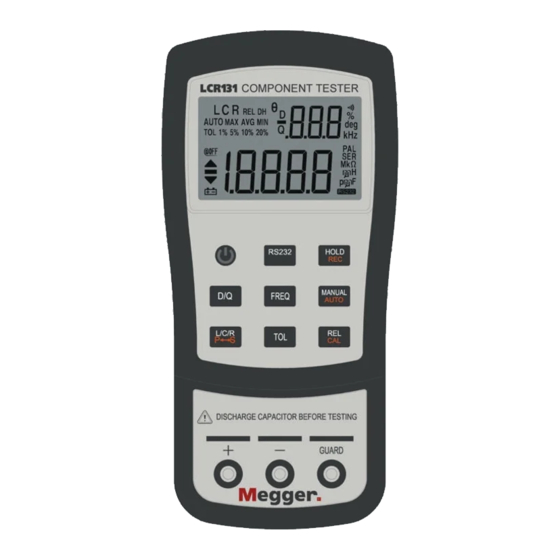
Page 8: Front Panel Illustration
Parallel and series mode selection button Tolerance mode selection button Data hold, Maximum, Minimum and Average reading selection button Range selection button 10. Relative mode and Calibration selection button 11. DC 12V adaptor input 12. Input sockets and Terminals Figure-1. Front panel for LCR131. -
Page 9: Lcd Display Illustration
LCD Display Illustration Figure 2. LCD Display. AUTO: Auto-ranging indicator LCR: L, C or R function indicator MAX: Maximum reading indicator AVG: Average reading indicator REL: Relative mode indicator MIN: Minimum reading indicator DH: Data hold indicator Q: Quality factor indicator 10. - Page 10 : Low battery indicator 21. PAL: Parallel mode indicator 22. SER: Series mode indicator 23. Mk : Resistance (Ohm) indicator : Inductance (Henry) indicator : Capacitance (Farad) indicator : RS232 indicator Special Indication Characters : Indicates short connectors : Indicates open connectors : Indicates calibration mode : Indicates damaged or open fuse...
-
Page 11: How To Operate
How To Operate Caution When measuring within a circuit, the circuit must be de-energized before connecting the test leads. Instruments used in dusty or dirty environment should be wiped and cleaned regularly. Do not expose instrument to direct sunlight or other heat sources for long periods. - Page 12 Inductance Measurement 1. Press the "POWER" button to turn on the meter. 2. Press “L/C/R” button to select inductance measurement. 3. Insert an inductor into component receptacle socket or connect the test clip to the component leads as required. 4. Press “FREQ” button to select testing frequency. 5.
- Page 13 Capacitance Measurement 1. Press "POWER" button to turn on the meter. 2. Press “L/C/R” button to select capacitance measurement. 3. Insert a capacitor into the component receptacle socket or connect the test clip to the component leads as required. 4. Press “FREQ” button to select testing frequency. 5.
- Page 14 Resistance Measurement 1. Press "POWER" button to turn on the meter. 2. Press “L/C/R” button to select Resistance measurement. 3. Insert a resistor into the component receptacle socket or connect the test clip to the component leads as required. 4. Press “FREQ” button to select testing frequency. 5.
-
Page 15: Operating Instructions
Operating Instructions Data Hold This data hold function allows the operator to freeze the display. To enter this mode, press the "HOLD" pushbutton; press again to release. Static Recording Press the "REC" pushbutton for more than one second to enter the static recording mode. The maximum and minimum readings are then stored in memory, while a beeping tone is produced when a new tested value has been recorded. -
Page 16: Test Frequency
Test Frequency Default testing frequency is 1KHz. Push "FREQ" key to select the desired test frequency. L/C/R Function Selector Press "L/C/R" pushbutton to select the desired L, C or R function. Relative Press the "REL" key to enter the relative mode and store the display reading as a reference value. -
Page 17: Auto/Manual Ranging
Notes: 1. The tolerance mode can not be activated if the display is either "OL" or "0000"; nor can it be activated where capacitance value is below 10 counts. 2. Tolerance mode is only available in manual ranging; however, activation while in auto-ranging will automatically set the meter to manual ranging and cause calibration prompts to be displayed in the relevant ranges. -
Page 18: Calibration
Calibration Calibration is available to all ranges. Simply press and hold "CAL" button for more than one second to enter the calibration mode and calibration prompts will be displayed. Follow the prompts for open connector ( ) or short connector ( ) connection and press the "CAL"... -
Page 19: Auto Power Off/ Disable Auto Power Off
Auto Power Off/ Disable Auto Power Off When the meter has not been used for five minutes after the last operation, a long "beep" tone will sound. The meter will then automatically enter a "sleep" mode and there will be no display on the LCD. - Page 20 Text side facing up. Figure-8. Cable Connection Of Communication...
-
Page 21: General Specification
General Specification LCR131 Parameters Measured L/C/R/D/Q Measuring Circuit Mode Inductance (L) –Defaults to series mode Capacitance/ Resistance (C/R) -Defaults to parallel mode Displays L/C/R: Maximum display 19999 D/Q: Maximum display 999 (Auto Range). Ranging Mode Auto & Manual Measuring Terminals... -
Page 22: Electrical Specification
Electrical Specification Accuracy is expressed as: ± (% of reading + no. of least significant digits) at 23 ±5 and <75% R.H. Resistance (parallel mode) Test Frequency: 120Hz / 1KHz Maximum Accuracy Range Specified Note Display @120 Hz @1KHz 2.0%+8 2.0%+8 After open cal. - Page 23 Test Frequency: 1 KHz Maximum Accuracy Range Spec. Note Display Capacitance 1.999mF 3.0%+5 10%+100/Cx+5 After short (DF<0.1) cal. (DF<0.1) 1.0%+5 2.0%+100/Cx+5 After short 200μF 199.99μF (DF<0.1) cal. (DF<0.1) 0.7%+3 0.7%+100/Cx+5 20μF 19.999μF (DF<0.5) (DF<0.5) 2000nF 1999.9nF 0.7%+3 0.7%+100/Cx+5 (DF<0.5) (DF<0.5) 200nF 199.99nF 0.7%+3...
- Page 24 Inductance (Series mode) Test Frequency: 120Hz Maximum Accuracy (DF<0.5) Range Spec. Note Display Inductance 1000H 999.9H 1.0%+(Lx 2%+100/Lx+5 After open cal. /10000) %+5 200H 199.99H 0.7%+(Lx 1.2%+100/Lx+5 /10000)%+5 19.999H 0.7%+(Lx 1.2%+100/Lx+5 /10000)%+5 2000m 1999.9mH 0.7%+(Lx 1.2%+100/Lx+5 /10000)%+5 200mH 199.99mH 1.0%+(Lx 3%+100/Lx+5 After short cal.
-
Page 25: Maintenance
MAINTENANCE WARNING To avoid electrical shock, do not perform any servicing unless you are qualified to do so. SERVICE If the instrument fails to operate, check battery and test leads, and replace as necessary. If the instrument still doesn’t work, confirm operating procedure as described in this User Manual. - Page 26 Fuse Replacement The meter can self-detect if its input protective fuse is either ruptured or damaged. In this case, the LCD will display the symbol "FUSE" and an audible beep will sound continuously, warning the user to replace the damaged fuse. While replacing the fuse, the power must be completely shut off.
- Page 27 Cleaning the Meter WARNING To avoid electrical shock or damage to the meter, never allow water to access the inside of the case. Before cleaning this meter, make sure the power is switched to OFF, and remove external DC adaptor. To clean the meter, wipe the dirt away with gauze or soft cloth soaked with diluted neutral detergent.
- Page 28 T +33 (1) 30.16.08.90 F +33 (1) 34.61.23.77 This instrument is manufactured in the United Kingdom. The company reserves the right to change the specification or design without prior notice. Megger is a registered trademark Part No LCR131_UG_V02 0205 www.megger.com...
Need help?
Do you have a question about the LCR131 and is the answer not in the manual?
Questions and answers