
Related Manuals for Deep Sea Electronics Plc DSE5110


Summary of Contents for Deep Sea Electronics Plc DSE5110
- Page 1 COMPLEX SOLUTIONS MADE SIMPLE. DEEP SEA ELECTRONICS PLC DSE5110 AUTOSTART CONTROL MODULE OPERATING MANUAL CALL US TODAY REQUEST A QUOTE SHOP ONLINE 1-888-POWER-58 parts@genpowerusa.com www.genpowerusa.com...
- Page 2 Deep Sea Electronics Plc at the address above. Any reference to trademarked product names used within this publication is owned by their respective companies. Deep Sea Electronics Plc reserves the right to change the contents of this document without prior notice. Part No. 057-009 5110 Operating Manual Issue 3.3...
-
Page 3: Table Of Contents
DSE Model 5110 Automatic Start Engine Management Instrumentation System TABLE OF CONTENTS Section Page INTRODUCTION ....................5 IDENTIFICATION OF “ORIGINAL” 5110 AND “NEW” 5110 ......6 CLARIFICATION OF NOTATION USED WITHIN THIS PUBLICATION..7 OPERATION ....................8 AUTOMATIC MODE OF OPERATION ................. 9 MANUAL OPERATION ....................... - Page 4 SPECIFICATION ..................37 COMMISSIONING ..................38 13.1.1 PRE-COMMISSIONING ..................... 38 TYPICAL WIRING DIAGRAM ..............39 FAULT FINDING ..................39 FACTORY DEFAULT SETTINGS ............. 41 ICONS AND LCD IDENTIFICATION ............42 17.1 PUSH BUTTONS ......................42 17.2 STATUS / MEASUREMENT UNITS ................42 17.3 ALARM INDICATIONS ....................
-
Page 5: Introduction
DSE Model 5110 Automatic Start Engine Management Instrumentation System 1 INTRODUCTION The DSE 5110 autostart module has been designed to allow the OEM to meet increasing demand within the industry. It has been primarily designed to allow the user to start and stop the generator. The user also has the facility to view all the system operating parameters via the LCD display. -
Page 6: Identification Of "Original" 5110 And "New" 5110
2 IDENTIFICATION OF “ORIGINAL” 5110 AND “NEW” 5110 NOTE:- In April 2005, the 5110 controller was updated to include PC configuration. At this time, a few minor changes to the front panel configuration were also made. This manual covers both the “original” and the “new” 5110 controller (V2 onwards). The “new”... -
Page 7: Clarification Of Notation Used Within This Publication
© Deep Sea Electronics Plc owns the copyright to this manual, which cannot be copied, reproduced or disclosed to a third party without prior written permission. Compliant with BS EN 60950 Low Voltage Directive... -
Page 8: Operation
4 OPERATION The following description details the sequences followed by a module containing the standard ‘factory configuration’. Always refer to your configuration source for the exact sequences and timers observed by any particular module in the field. Part No. 057-009 5110 Operating Manual Issue 3.3 3/1/2006 CALL US TODAY... -
Page 9: Automatic Mode Of Operation
DSE Model 5110 Automatic Start Engine Management Instrumentation System 4.1 AUTOMATIC MODE OF OPERATION This mode is activated by pressing the pushbutton. An LED indicator beside the button confirms this action. When a Remote Start signal is applied to the remote start input, the following sequence is initiated:- The Remote Start Active indicator illuminates (if configured). -
Page 10: Manual Operation
4.2 MANUAL OPERATION To initiate a start sequence in MANUAL, press the pushbutton. When the controller is in the manual mode (indicated by an LED indicator beside the button), pressing the START (I) button will initiate the start sequence. NOTE:- There is no Start Delay in this mode of operation. NOTE:- When in manual mode, the remote start input cannot be used to begin the start sequence. -
Page 11: Protections
DSE Model 5110 Automatic Start Engine Management Instrumentation System 5 PROTECTIONS The module will indicate that an alarm has occurred in several ways; The “Common alarm” LED will illuminate (Warning = Red steady, Shutdown = Red Flashing) If appropriate, the LCD display or LED indicators will display the appropriate alarm icon i.e. for battery charging failure : R P M 51 . -
Page 12: Warnings
5.1 WARNINGS Warnings are non-critical alarm conditions and do not affect the operation of the generator system, they serve to draw the operators attention to an undesirable condition. In the event of a warning alarm the LCD will display:- BATTERY CHARGE FAILURE, if the module does not detect a voltage from the warning light terminal on the auxiliary charge alternator the icon will illuminate. -
Page 13: Shutdowns
DSE Model 5110 Automatic Start Engine Management Instrumentation System 5.2 SHUTDOWNS Shutdowns are latching and stop the Generator. The alarm must be cleared, and the fault removed to reset the module. In the event of a shutdown alarm the LCD will display: - (flashing). - Page 14 OIL PRESSURE SENDER OPEN CIRCUIT, if the module detects a loss of signal from the oil pressure sender (open circuit) a shutdown is initiated. The LCD will indicate:- (Steady) (And ‘-----‘ on the engine oil pressure instrument). Sender failure is not delayed; it is an immediate shutdown.
-
Page 15: Description Of Controls
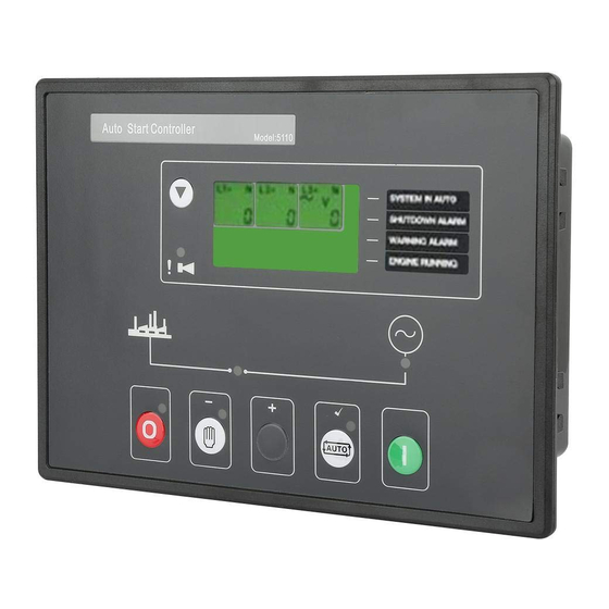
DSE Model 5110 Automatic Start Engine Management Instrumentation System 6 DESCRIPTION OF CONTROLS The following section details the function and meaning of the various controls on the module. Instrumentation page LCD Display button Common alarm LED User configurable indicators Operation and configuration buttons FIG2 Part No. -
Page 16: Typical Lcd Display Screens
6.1 TYPICAL LCD DISPLAY SCREENS INSTRUMENTS The LCD displays the various engine parameters such as ‘ENGINE SPEED’, ‘OIL PRESSURE’, ‘HOURS RUN’, etc. L 1- L 2 L 2- L 3 L 3- L 1 Each instrument is displayed with the appropriate units of measure. 4 1 7. -
Page 17: Lcd Display Areas
DSE Model 5110 Automatic Start Engine Management Instrumentation System 6.2 LCD DISPLAY AREAS Instrument Values Display Information & Units of Measure Alarm Icons User Definable Alarms/Indicators NOTE:- The Engine Hours Run counter will only display the accumulated hours to the nearest 12 Minutes (0.2Hr). -
Page 18: Viewing The Instruments
6.3 VIEWING THE INSTRUMENTS It is possible to manually scroll to display the different instruments by repeatedly operating the scroll button. Once selected the instrument will remain on the LCD display until the user selects a different instrument or after a period of inactivity the module will revert to the initial display (Hz/RPM). Instrument Page Order:- •... -
Page 19: Indicators
DSE Model 5110 Automatic Start Engine Management Instrumentation System 6.4 INDICATORS COMMON ALARM LCD indicators These indicate when an alarm condition is present. The Alarm icons or LED’s will detail the exact nature of the (warning) or (shutdown) alarm. USER CONFIGURABLE LCD INDICATORS These LCD’s can be configured by the user to indicate any on of the different functions based around the following:-... -
Page 20: Power Up Lcd Display
7 POWER UP LCD DISPLAY In April 2005, the 5110 controller was updated to include PC configuration. At this time, a few minor changes to the front panel configuration were also made. This section details the power up display of the “new” 5110 module. When DC power is first applied to the 5110 controller, a short LCD test is performed that illuminates all LCD segments. -
Page 21: Event Log
DSE Model 5110 Automatic Start Engine Management Instrumentation System 8 EVENT LOG Model 5110 features an integral 20 item event log. This log contains the last 20 shutdown alarms registered by the controller. ENTERING EVENT LOG VIEWER NOTE:- Entering the event log will place the module into STOP mode, shutting down the engine if it is already running. -
Page 22: Front Panel Configuration
9 FRONT PANEL CONFIGURATION In April 2005, the 5110 controller was updated to include PC configuration. At this time, a few minor changes to the front panel configuration were also made. This section details the configuration editor of the “new” 5110 module. For details of the configuration editor for the “original”... -
Page 23: Editing An Analogue Value
DSE Model 5110 Automatic Start Engine Management Instrumentation System 9.2 EDITING AN ANALOGUE VALUE Enter the front panel configuration editor as described above. Press the button to enter adjust mode. icons in the module display), pressing the + or – When in adjust mode (indicated by the flashing buttons will change the selected parameter to the desired value. -
Page 24: Timers & Analogue Settings
9.4 TIMERS & ANALOGUE SETTINGS Parameter Type Default 0 - Start delay Timer 1 - Preheat Timer 2 - Crank attempt Timer 3 - Crank rest Timer 4 - Safety delay Timer 5 - Warming up Timer 6 - Return delay Timer 7 - Cooling run Timer... -
Page 25: List Item Settings
DSE Model 5110 Automatic Start Engine Management Instrumentation System 9.5 LIST ITEM SETTINGS Factory default settings are in bold italicised text. Parameter Selections 20 - Alternator poles 0,2,4,6,8 21 - Oil pressure input 0 - Not used 1 - Digital, close for low pressure 2 - Digital, open for low pressure... -
Page 26: Configurable Outputs
9.6 CONFIGURABLE OUTPUTS Factory default settings are in bold italicised text. Parameter Selection 26 – Output 1 0 - Unused 1 - Preheat mode 0 2 - Air flap 3 – Close Generator 4 - Energise to stop 5 - Engine running 6 - Shutdown alarm 7 - System in auto 8 - Auxiliary input 1 active... - Page 27 DSE Model 5110 Automatic Start Engine Management Instrumentation System CONFIGURABLE OUTPUTS (CONTINUED) Factory default settings are in bold italicised text. Parameter Selection 28 – Output 3 0 - Unused 1 - Preheat mode 0 2 - Air flap 3 - Load transfer 4 - Energise to stop 5 - Engine running 6 - Shutdown alarm...
-
Page 28: Lcd Indicators
9.7 LCD INDICATORS Factory default settings are in bold italicised text. Parameter Selection 29 - LCD 1 0 - Unused 1 - Preheat mode 0 2 - Air flap 3 - Load transfer 4 - Energise to stop 5 - Engine running 6 - Shutdown alarm 7 - System in auto 8 - Auxiliary input 1 active... - Page 29 DSE Model 5110 Automatic Start Engine Management Instrumentation System LCD INDICATORS (CONTINUED) Factory default settings are in bold italicised text. Parameter Selection 31 - LCD 3 0 - Unused 1 - Preheat mode 0 2 - Air flap 3 - Load transfer 4 - Energise to stop 5 - Engine running 6 - Shutdown alarm...
-
Page 30: Configurable Inputs
9.8 CONFIGURABLE INPUTS Factory default settings are in bold italicised text. Parameter Selection 33 – Input 1 0 - Delayed, Warning, close to activate 1 - Delayed, Warning, open to activate 2 - Immediate, Warning, close to activate 3 - Immediate, Warning, open to activate 4 - Delayed, Shutdown, close to activate 5 - Delayed, Shutdown, open to activate 6 -Immediate, Shutdown, close to activate... -
Page 31: Installation Instructions
DSE Model 5110 Automatic Start Engine Management Instrumentation System 10 INSTALLATION INSTRUCTIONS The model DSE 5110 Module has been designed for front panel mounting. Fixing is by 4 clips for easy assembly. 10.1 PANEL CUT-OUT 160.00mm (6.3”) 220.00mm (8.7”) FIG 3 Maximum panel thickness –... -
Page 32: Front Panel Layout
10.4 FRONT PANEL LAYOUT 10.5 REAR PANEL LAYOUT Part No. 057-009 5110 Operating Manual Issue 3.3 3/1/2006 CALL US TODAY REQUEST A QUOTE SHOP ONLINE 1-888-POWER-58 parts@genpowerusa.com www.genpowerusa.com... -
Page 33: Electrical Connections
DSE Model 5110 Automatic Start Engine Management Instrumentation System 11 ELECTRICAL CONNECTIONS Connections to the Module are via plug and sockets. 11.1 CONNECTION DETAILS The following describes the connections and recommended cable sizes to the 7 plugs and sockets on the rear of the Module. -
Page 34: Plug "G" 5 Way
11.1.4 PLUG “G” 5 WAY PIN No DESCRIPTION CABLE SIZE NOTES CT Secondary for L1 2.5mm² (13 AWG) Connect to secondary of L1 monitoring CT Secondary for L2 2.5mm² (13 AWG) Connect to secondary of L2 monitoring CT Secondary for L3 2.5mm²... -
Page 35: Connector Function Details
DSE Model 5110 Automatic Start Engine Management Instrumentation System 11.2 CONNECTOR FUNCTION DETAILS The following describes the functions of the 3 connectors on the rear of the module. See rear panel layout FIG 5. 11.2.1 PLUG “A” 8 WAY DESCRIPTION DC Supply Negative. -
Page 36: Plug "F" 4 Way
11.2.3 PLUG “F” 4 WAY DESCRIPTION Generator L1 sensing input. Connect to alternator L1 output. Generator L2 sensing input. Connect to alternator L2 output. If using single phase only do not connect this terminal. Generator L3 sensing input. Connect to alternator L3 output. If using single phase only do not connect this terminal. -
Page 37: Specification
DSE Model 5110 Automatic Start Engine Management Instrumentation System 12 SPECIFICATION DC Supply 8.0 V to 35 V Continuous. Cranking Dropouts Able to survive 0 V for 50mS, providing supply was at least 10 V before dropout and supply recovers to 5V. This is achieved without the need for internal batteries. -
Page 38: Commissioning
13 COMMISSIONING 13.1.1 PRE-COMMISSIONING Before the system is started, it is recommended that the following checks are made:- 7.1. The unit is adequately cooled and all the wiring to the module is of a standard and rating compatible with the system. 7.2. -
Page 39: Typical Wiring Diagram
DSE Model 5110 Automatic Start Engine Management Instrumentation System 14 TYPICAL WIRING DIAGRAM 15 FAULT FINDING Part No. 057-009 5110 Operating Manual Issue 3.3 3/1/2006 CALL US TODAY REQUEST A QUOTE SHOP ONLINE 1-888-POWER-58 parts@genpowerusa.com www.genpowerusa.com... - Page 40 SYMPTOM POSSIBLE REMEDY Unit is inoperative Check the battery and wiring to the unit. Check the DC supply. Check the DC fuse. Unit shuts down Check DC supply voltage is not above 35 Volts or below 9 Volts Check the operating temperature is not above 70 °C. Check the DC fuse. Unit locks out on Emergency Stop If an Emergency Stop Switch is not fitted, ensure that a positive is connected to the Emergency Stop input.
-
Page 41: Factory Default Settings
DSE Model 5110 Automatic Start Engine Management Instrumentation System 16 FACTORY DEFAULT SETTINGS Modules are shipped from the factory with parameters set to the following values. These can be user adjusted via the front panel configuration editor. For further details on adjustment via the front panel editor, see the section entitled “Front panel configuration”... -
Page 42: Icons And Lcd Identification
17 ICONS AND LCD IDENTIFICATION 17.1 PUSH BUTTONS Display Description Display Description Display Description Stop/Reset Auto mode Manual mode Start (when in Scroll manual mode) 17.2 STATUS / MEASUREMENT UNITS Display Description Display Description Display Description Phase Phase Phase L 1 - L 2 - Phase - Neutral Phase - Neutral... -
Page 43: Appendix
DSE Model 5110 Automatic Start Engine Management Instrumentation System 18 APPENDIX 18.1 ALTERNATIVE WIRING TOPOLOGIES The 5110 series controllers can support different wiring topologies (AC systems) to suit the systems in use worldwide. The ‘Typical connection diagram’ details how to connect the module when used in a 3 phase, 4 wire system (3 phase star connected alternators). -
Page 44: Phase, 3 Wire
18.1.3 2 PHASE, 3 WIRE Two measured phases with Neutral as a centre tap between the two live phases. Part No. 057-009 5110 Operating Manual Issue 3.3 3/1/2006 CALL US TODAY REQUEST A QUOTE SHOP ONLINE 1-888-POWER-58 parts@genpowerusa.com www.genpowerusa.com... -
Page 45: Sender Wiring Recommendations
DSE Model 5110 Automatic Start Engine Management Instrumentation System 18.2 SENDER WIRING RECOMMENDATIONS 18.2.1 EARTH RETURN SENDERS Connection Name Terminal Number Oil pressure Sender Coolant temperature sender Sender common NOTE:- . It is important that terminal 47 (sender common) is soundly connected to an earth point on the ENGINE BLOCK, not within the control panel, and must be a sound electrical connection to the sender bodies. -
Page 46: Choosing The Correct C.t.s
18.3 CHOOSING THE CORRECT C.T.S The VA burden of the 5110 on the measurement CTs (Current transformers) is 2.5VA. However depending upon the type and length of cabling between the CTs and the modules, CTs with a greater VA rating than 2.5VA are required. The distance between the CTs and the measuring module should be estimated and cross-referenced against the chart... -
Page 47: Input Expansion
DSE Model 5110 Automatic Start Engine Management Instrumentation System 18.4 INPUT EXPANSION It is possible to increase the number of monitored inputs available by utilising a DSE 54x Protection Expansion/Annunciator. Please refer to our Technical department for details. 18.5 STANDBY GENERATING SET? The 5110 needs to be given a remote start signal to initiate an engine start. -
Page 48: Front Panel Configuration (Original 5110)
18.7 FRONT PANEL CONFIGURATION (ORIGINAL 5110) In April 2005, the 5110 controller was updated to include PC configuration. At this time, a few minor changes to the front panel configuration were also made. This section details the configuration editor of the “Original” 5110 module. To identify the “original” and Identification of “original”... -
Page 49: Call Us Today 1-888-Power
DSE Model 5110 Automatic Start Engine Management Instrumentation System CONFIGURABLE OUTPUTS LCD INDICATORS Factory default settings are in bold italicised text. Factory default settings are in bold italicised text. Parameter Selection Parameter Selection 27 - LCD 1 0 - Unused 24 - Output 1 0 - Unused 1 - Preheat mode 0... - Page 50 LCD INDICATORS (CONTINUED) CONFIGURABLE INPUTS Factory default settings are in bold italicised text. Factory default settings are in bold italicised text. Parameter Selection Parameter Selection 29 - LCD 3 0 - Unused 31 - Input 1 0 - Delayed, Warning, close to activate 1 - Preheat mode 0 1 - Delayed, Warning, open to activate 2 - Air flap...
-
Page 51: Front Panel Configuration Mk2 5110 V3
DSE Model 5110 Automatic Start Engine Management Instrumentation System 18.8 FRONT PANEL CONFIGURATION MK2 5110 V3 TIMERS & ANALOGUE SETTINGS ACCESSING THE CONFIGURATION EDITOR Parameter Type Default Press the Stop/Reset and Info buttons 0 - Start delay Timer simultaneously. 1 - Preheat Timer 2 - Crank attempt Timer... - Page 52 CONFIGURABLE OUTPUTS Factory default settings are in bold italicised text. Factory default settings are in bold italicised text. Parameter Selection Parameter Selection 24 – Output 1 0 - Unused 26 – Output 3 0 - Unused 1 - Preheat mode 0 1 - Preheat mode 0 2 - Air flap 2 - Air flap...
- Page 53 DSE Model 5110 Automatic Start Engine Management Instrumentation System LCD INDICATORS Factory default settings are in bold italicised text. Factory default settings are in bold italicised text. Parameter Selection Parameter Selection 29 - LCD 3 0 - Unused 27 - LCD 1 0 - Unused 1 - Preheat mode 0 1 - Preheat mode 0 2 - Air flap...
- Page 54 CONFIGURABLE INPUTS Factory default settings are in bold italicised text. Parameter Selection 31 – Input 1 0 - Delayed, Warning, close to activate 1 - Delayed, Warning, open to activate 2 - Immediate, Warning, close to activate 3 - Immediate, Warning, open to activate 4 - Delayed, Shutdown, close to activate 5 - Delayed, Shutdown, open to activate 6 -Immediate, Shutdown, close to activate...
Need help?
Do you have a question about the DSE5110 and is the answer not in the manual?
Questions and answers