
Related Manuals for Deep Sea Electronics Plc DSE5320


Summary of Contents for Deep Sea Electronics Plc DSE5320
- Page 1 COMPLEX SOLUTIONS MADE SIMPLE. DEEP SEA ELECTRONICS PLC DSE5320 AUTO MAINS FAILURE MODULE OPERATING MANUAL CALL US TODAY REQUEST A QUOTE SHOP ONLINE 1-888-POWER-58 parts@genpowerusa.com www.genpowerusa.com...
- Page 2 Sea Electronics Plc at the address above. Any reference to trademarked product names used within this publication is owned by their respective companies. Deep Sea Electronics Plc reserves the right to change the contents of this document without prior notice. Part No. 057-014 5320 OPERATING MANUAL ISSUE 5.1...
- Page 3 DSE Model 5320 Automatic Mains Failure & Instrumentation System Operators Manual TABLE OF CONTENTS Section Page INTRODUCTION ....................5 CLARIFICATION OF NOTATION USED WITHIN THIS PUBLICATION..5 OPERATION ....................6 AUTOMATIC MODE OF OPERATION ................7 ...
- Page 4 DSE Model 5320 Automatic Mains Failure & Instrumentation System Operators Manual 8.2.1 PLUG “A” 8 WAY ......................43 8.2.2 PLUG “B” 11 WAY ...................... 43 8.2.3 PLUG “C” 3 WAY ......................44 8.2.4 PLUG “D”...
-
Page 5: Introduction
DSE Model 5320 Automatic Mains Failure & Instrumentation System Operators Manual 1 INTRODUCTION The DSE 5320 automatic mains failure module has been primarily designed to monitor the mains (utility) supply, starting the generator automatically should it fall out of limits. Transfer of the load is automatic upon a mains supply failure. -
Page 6: Operation
DSE Model 5320 Automatic Mains Failure & Instrumentation System Operators Manual 3 OPERATION The following description details the sequences followed by a module containing the standard ‘factory configuration’. Always refer to your configuration source for the exact sequences and timers observed by any particular module in the field. -
Page 7: Automatic Mode Of Operation
DSE Model 5320 Automatic Mains Failure & Instrumentation System Operators Manual 3.1 AUTOMATIC MODE OF OPERATION NOTE:- If a digital input configured to panel lock is active, changing module modes will not be possible. Viewing the instruments is NOT affected by panel lock. If panel lock is active the Panel lock indicator (if configured) illuminates. - Page 8 DSE Model 5320 Automatic Mains Failure & Instrumentation System Operators Manual After the starter motor has disengaged, the Safety On timer is activated, allowing Oil Pressure, High Engine Temperature, Under-speed, Charge Fail and any delayed Auxiliary fault inputs to stabilise without triggering the fault.
-
Page 9: Manual Operation
DSE Model 5320 Automatic Mains Failure & Instrumentation System Operators Manual 3.2 MANUAL OPERATION NOTE:- If a digital input configured to panel lock is active, changing module modes will not be possible. Viewing the instruments and event logs is NOT affected by panel lock. If panel lock is active the Panel lock indicator (if configured) illuminates. -
Page 10: Test Operation
DSE Model 5320 Automatic Mains Failure & Instrumentation System Operators Manual 3.3 TEST OPERATION NOTE:- If a digital input configured to panel lock is active, changing module modes will not be possible. Viewing the instruments and event logs is NOT affected by panel lock. If panel lock is active the Panel lock indicator (if configured) illuminates. -
Page 11: Protections
DSE Model 5320 Automatic Mains Failure & Instrumentation System Operators Manual 4 PROTECTIONS When an alarm is present the Audible Alarm will sound and the Common alarm LED if configured will illuminate. The audible alarm can be silenced by pressing the ‘Mute’ button The LCD display will jump from the ‘Information page’... -
Page 12: Warnings
DSE Model 5320 Automatic Mains Failure & Instrumentation System Operators Manual 4.1 WARNINGS Warnings are non-critical alarm conditions and do not affect the operation of the generator system, they serve to draw the operators attention to an undesirable condition. In the event of an alarm the LCD will jump to the alarms page, and scroll through all active warnings and shutdowns. -
Page 13: Analogue Pre-Alarms
DSE Model 5320 Automatic Mains Failure & Instrumentation System Operators Manual AUXILIARY INPUTS, auxiliary inputs can be user configured and will display the message as written by the user. Example Alarm Warning Bearing temp high LOW FUEL LEVEL. will be displayed if the fuel level detected by the fuel level sender falls below the low fuel level setting. - Page 14 DSE Model 5320 Automatic Mains Failure & Instrumentation System Operators Manual OVERSPEED, if the engine speed exceeds the pre-alarm trip a warning is initiated. Alarm Warning Overspeed will be displayed. It is an immediate warning. Alarm Warning Overspeed UNDERSPEED, if the engine speed falls below the pre-set pre-alarm after the Safety On timer has expired, a warning is initiated.
-
Page 15: High Current Warning Alarm
DSE Model 5320 Automatic Mains Failure & Instrumentation System Operators Manual 4.3 HIGH CURRENT WARNING ALARM GENERATOR HIGH CURRENT, if the module detects a generator output current in excess of the pre-set trip a warning is initiated. Alarm Warning High Current will be displayed. If this high current condition continues for an excess period of time, then the alarm is escalated to a shutdown condition. - Page 16 DSE Model 5320 Automatic Mains Failure & Instrumentation System Operators Manual HIGH ENGINE TEMPERATURE if the module detects that the engine coolant temperature has exceeded the high engine temperature trip setting level after the Safety On timer has expired, a shutdown will occur. Alarm Shutdown High Engine Temperature will be displayed.
- Page 17 DSE Model 5320 Automatic Mains Failure & Instrumentation System Operators Manual GENERATOR LOW VOLTAGE if the module detects a generator output voltage below the below the pre-set trip after the Safety On timer has expired, a shutdown is initiated. Alarm Shutdown Low Volts will be displayed. Alarm Shutdown AC Undervolts...
-
Page 18: High Current Shutdown Alarm
DSE Model 5320 Automatic Mains Failure & Instrumentation System Operators Manual CAN ECU FAIL If the module is configured for CAN instruments and receives a “fail” message from the engine control unit, the engine is shutdown and ‘Can ECU fail” is shown on the module’s display. Example The display will alternate Alarm... -
Page 19: Electrical Trips
DSE Model 5320 Automatic Mains Failure & Instrumentation System Operators Manual 4.6 ELECTRICAL TRIPS Electrical trips are latching and stop the Generator but in a controlled manner. On initiation of the electrical trip condition the module will de-energise the ‘Close Generator’ Output to remove the load from the generator. Once this has occurred the module will start the Cooling timer and allow the engine to cool off-load before shutting down the engine. -
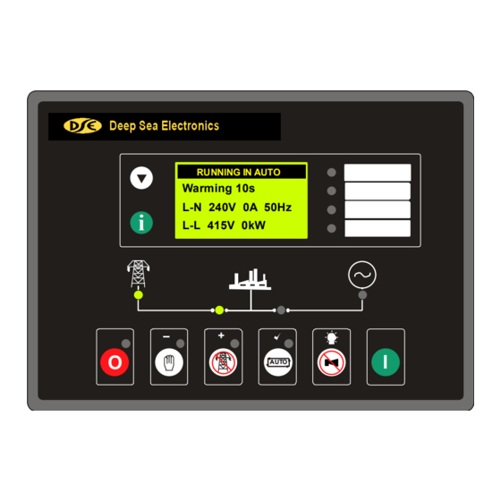
Page 20: Description Of Controls
DSE Model 5320 Automatic Mains Failure & Instrumentation System Operators Manual 5 DESCRIPTION OF CONTROLS The following section details the function and meaning of the various controls on the module. Scroll Down Next page Configurable LEDs Deep Sea Electronics Model 5220 RUNNING IN AUTO Warming 10s L-N 240V 0A 50Hz... - Page 21 DSE Model 5320 Automatic Mains Failure & Instrumentation System Operators Manual Deep Sea Electronics Model 5220 RUNNING IN AUTO Warming 10s L-N 240V 0A 50Hz L-L 415V 0kW AUTO Mains Indication LED. Close Mains Output Close Generator Generator available Lit when The Mains Is LED.
-
Page 22: Typical Lcd Display Screens
DSE Model 5320 Automatic Mains Failure & Instrumentation System Operators Manual 5.1 TYPICAL LCD DISPLAY SCREENS 5.1.1 TYPICAL STATUS DISPLAY Waiting in auto Indicates that the module is in Automatic, and that the mains is on load (closed). The unit will respond to either a mains failure or an Mains on load active remote start. -
Page 23: Typical Event Display
DSE Model 5320 Automatic Mains Failure & Instrumentation System Operators Manual 5.1.4 TYPICAL EVENT DISPLAY Event log 21:15:00 On the 10 September 2005 at 21:15 the unit detected that the oil 10th September 2005 pressure was below the pre-set trip level, and has shutdown the Low oil pressure generator. -
Page 24: Instrument Page Content
DSE Model 5320 Automatic Mains Failure & Instrumentation System Operators Manual 5.2.1 INSTRUMENT PAGE CONTENT • Engine speed • Oil Pressure • Coolant temperature • Engine Hours Run • DC Battery Voltage • Charge alternator voltage • Modem status (GSM) •... -
Page 25: Manually Selecting An Instrument
DSE Model 5320 Automatic Mains Failure & Instrumentation System Operators Manual 5.2.2 MANUALLY SELECTING AN INSTRUMENT Running in auto Default display Generator on load Engine speed Pressing the DOWN button the LCD will then show Engine speed 1500 Oil pressure Pressing the DOWN button the LCD will then show Oil pressure Pressing the... -
Page 26: Gsm Modem Status
DSE Model 5320 Automatic Mains Failure & Instrumentation System Operators Manual 5.2.3 GSM MODEM STATUS When configured and connected to a GSM Modem for cellular network communications, the GSM MODEM STATUS screen shows the following information. Modem Status The modem is reset by the 5300 series controller. Resetting modem Modem Status Modem initialising strings are sent to the modem (as set in the Edit Config | Comms... -
Page 27: Can Error Messages
DSE Model 5320 Automatic Mains Failure & Instrumentation System Operators Manual 5.2.4 CAN ERROR MESSAGES On CAN enabled 53xx controllers connected to a suitable CAN ECU, alarm status messages are transmitted to the 53xx controller and displayed on the alarms page. Alarm Alarm Here the ECU code is interpreted by the module, which... -
Page 28: User Configurable Indicators
DSE Model 5320 Automatic Mains Failure & Instrumentation System Operators Manual 5.4 USER CONFIGURABLE INDICATORS These LEDs can be configured by the user to indicate any one of 100+ different functions based around the following:- • Indications - Monitoring of a digital input and indicating associated functioning user’s equipment - Such as Battery Charger On or Louves Open, etc. -
Page 29: Front Panel Configuration
DSE Model 5320 Automatic Mains Failure & Instrumentation System Operators Manual 6 FRONT PANEL CONFIGURATION This configuration mode allows the operator limited customising of the way the module operates. Operation Detail To enter the ‘configuration mode’ press both the INFO and STOP buttons together. - Page 30 DSE Model 5320 Automatic Mains Failure & Instrumentation System Operators Manual If the module PIN number has been set, the PIN number request is then shown. The configuration cannot be viewed or changed until the PIN number is correctly entered. Enter either the ‘main’...
-
Page 31: Editing A Value
DSE Model 5320 Automatic Mains Failure & Instrumentation System Operators Manual 6.2 EDITING A VALUE Oil pressure pre-alarm Press the Stop/Reset and Info buttons simultaneously. If the module PIN number has been set, the PIN number request is then shown. The configuration cannot be viewed or changed until the PIN number is correctly entered. -
Page 32: List Of Adjustable Parameters In 'Main Configuration Editor
DSE Model 5320 Automatic Mains Failure & Instrumentation System Operators Manual 6.2.1 LIST OF ADJUSTABLE PARAMETERS IN ‘MAIN CONFIGURATION EDITOR’ Section Parameter Display shows Values Low Oil Pressure warning Oil pressure pre-alarm Input settings 0-4bar (1.17bar) Low Oil Pressure shutdown Oil pressure shutdown 0-4bar (1.03bar) High Temperature warning... -
Page 33: List Of Adjustable Parameters In 'Application Editor
DSE Model 5320 Automatic Mains Failure & Instrumentation System Operators Manual 6.2.2 LIST OF ADJUSTABLE PARAMETERS IN ‘APPLICATION EDITOR’ Section Parameter Display shows Values Engine speed selection Application Alternative Frequency Disable, Enable Volts selection Alternative Voltage Disable, Enable AC System Wiring topography 3 phase 4 wire Single phase, 2 wire... -
Page 34: Editing The Current Date And Time
DSE Model 5320 Automatic Mains Failure & Instrumentation System Operators Manual 6.2.3 EDITING THE CURRENT DATE AND TIME The date and time can be set either using the 5xxx series configuration or the front panel configuration editer. NOTE:- The 5320 controller maintains the current date and time so long as it is connected to a DC supply within the operating range. - Page 35 DSE Model 5320 Automatic Mains Failure & Instrumentation System Operators Manual Date and time Press the button to ‘save’ the value, and select the month for adjustment. 19 Sep 2005 10:00 The month will start to flash. – Pressing the buttons will adjust the month to the desired value.
-
Page 36: Installation Instructions
DSE Model 5320 Automatic Mains Failure & Instrumentation System Operators Manual 7 INSTALLATION INSTRUCTIONS The model DSE 5320 Module has been designed for front panel mounting. Fixing is by 4 clips for easy assembly. 7.1 PANEL CUT-OUT 160.00mm (6.3”) 220.00mm (8.7”) FIG 3 Maximum panel thickness –... -
Page 37: Front Panel Layout
DSE Model 5320 Automatic Mains Failure & Instrumentation System Operators Manual 7.4 FRONT PANEL LAYOUT Deep Sea Electronics Model 5220 RUNNING IN AUTO Warming 10s L-N 240V 0A 50Hz L-L 415V 0kW AUTO FIG 5 REAR PANEL LAYOUT FIG 6 Part No. -
Page 38: Electrical Connections
DSE Model 5320 Automatic Mains Failure & Instrumentation System Operators Manual 8 ELECTRICAL CONNECTIONS Connections to the Module are via plug and sockets. 8.1 CONNECTION DETAILS The following describes the connections and recommended cable sizes to the 8 plugs and sockets on the rear of the Module. -
Page 39: Plug "B" 11 Way
DSE Model 5320 Automatic Mains Failure & Instrumentation System Operators Manual 8.1.2 PLUG “B” 11 WAY DESCRIPTION CABLE NOTES SIZE Charge fail / excite 2.5mm² Do not connect to ground (battery –ve) AWG 13 Auxiliary input 1 0.5mm² Switch to Negative AWG 20 Auxiliary input 2 0.5mm²... -
Page 40: Plug "C" 3 Way
DSE Model 5320 Automatic Mains Failure & Instrumentation System Operators Manual 8.1.3 PLUG “C” 3 WAY DESCRIPTION CABLE NOTES SIZE CAN port Common 0.5mm² Use only 120Ω CAN approved cable AWG 20 CAN port H 0.5mm² Use only 120Ω CAN approved cable AWG 20 CAN port L 0.5mm²... -
Page 41: Plug "F" 4 Way
DSE Model 5320 Automatic Mains Failure & Instrumentation System Operators Manual 8.1.6 PLUG “F” 4 WAY DESCRIPTION CABLE NOTES SIZE Generator L1 voltage 1.0mm² Connect to generator L1 output (AC) monitoring input AWG 18 (Recommend 2A fuse) Generator L2 voltage 1.0mm²... -
Page 42: Pc Configuration Interface Connector
DSE Model 5320 Automatic Mains Failure & Instrumentation System Operators Manual 8.1.9 PC CONFIGURATION INTERFACE CONNECTOR 8-way connector allows connection to PC via the 810 configuration interface. Module can then be re-configured utilising the 5xxx series configuration software. 8.1.10 EXPANSION OUTPUT CONNECTOR The expansion connector allows connection to the 157 relay expansion module or to the 548 LED Remote annunciator module. -
Page 43: Connector Function Details
DSE Model 5320 Automatic Mains Failure & Instrumentation System Operators Manual 8.2 CONNECTOR FUNCTION DETAILS The following describes the functions of the 8 connectors on the rear of the module. See rear panel layout FIG 5 . 8.2.1 PLUG “A” 8 WAY DESCRIPTION DC Supply System negative input. -
Page 44: Plug "C" 3 Way
DSE Model 5320 Automatic Mains Failure & Instrumentation System Operators Manual 8.2.3 PLUG “C” 3 WAY DESCRIPTION CAN port Common. Do not connect this terminal to earth. Use only screened 120Ω cable approved specifically for use in CAN applications. CAN port H. Use only screened 120Ω cable approved specifically for use in CAN applications. CAN port L. -
Page 45: Plug "F" 4 Way
DSE Model 5320 Automatic Mains Failure & Instrumentation System Operators Manual 8.2.6 PLUG “F” 4 WAY DESCRIPTION Generator L1 sensing input. Connect to alternator L1 output. Generator L2 sensing input. Connect to alternator L2 output. If using single phase only do not connect this terminal. -
Page 46: Specification
DSE Model 5320 Automatic Mains Failure & Instrumentation System Operators Manual 9 SPECIFICATION DC Supply Continuous voltage rating : 8V to 35V Cranking dip protection : Able to survive 0V for 50mS, providing supply was at least 10V before dropout and supply recovers to 5V. -
Page 47: Commissioning
DSE Model 5320 Automatic Mains Failure & Instrumentation System Operators Manual Electrical Safety BS EN 60950 Safety of information technology equipment, including electrical business equipment /Electromagnetic BS EN 61000-6-2 EMC Generic Emission Standard (Industrial) Compatibility BS EN 61000-6-4 EMC Generic Emission Standard (Industrial) Environmental BS EN 60068-2-1 Cold Temperature -30°C... - Page 48 DSE Model 5320 Automatic Mains Failure & Instrumentation System Operators Manual 10.4. To check the start cycle operation take appropriate measures to prevent the engine from starting (disable the operation of the fuel solenoid). After a visual inspection to ensure it is safe to proceed, connect the battery supply.
-
Page 49: Fault Finding
DSE Model 5320 Automatic Mains Failure & Instrumentation System Operators Manual 11 FAULT FINDING SYMPTOM POSSIBLE REMEDY Unit is inoperative Check the battery and wiring to the unit. Check the DC supply. Check the DC fuse. Unit shuts down Check DC supply voltage is not above 35 Volts or below 9 Volts Check the operating temperature is not above 70 °C. -
Page 50: Factory Default Configuration
DSE Model 5320 Automatic Mains Failure & Instrumentation System Operators Manual 12 FACTORY DEFAULT CONFIGURATION In the tables below, the icon indicates an item that can be adjusted from the module’s front panel editor. Absence of the icon beside an item means that adjustment of this parameter is only possible using the 5xxx series configuration software in conjunction with the P810 interface. - Page 51 DSE Model 5320 Automatic Mains Failure & Instrumentation System Operators Manual Input settings - Digital Value 1 Remote start Close to activate 2 Lamp test Close to activate 3 User configured Close to activate, Warning Active from safety on 4 User configured Close to activate, Shutdown Always active 5 User configured Close to activate, Shutdown Active from safety on...
- Page 52 DSE Model 5320 Automatic Mains Failure & Instrumentation System Operators Manual Timer settings Value Mains transient delay Start delay Pre-heat Cranking time Crank rest time Smoke limit Smoke limit off Safety on delay Overspeed overshoot Warming up time Transfer time 0.7s Breaker close pulse 0.5s...
- Page 53 DSE Model 5320 Automatic Mains Failure & Instrumentation System Operators Manual Engine settings – Crank disconnect Value Crank disconnect on generator frequency 21.0Hz Crank disconnect oil pressure <Disabled> Check oil pressure prior to starting Engine settings – speed Value Underspeed trip 1250 RPM Disabled Underspeed prealarm...
-
Page 54: Typical Wiring Diagram
DSE Model 5320 Automatic Mains Failure & Instrumentation System Operators Manual 13 TYPICAL WIRING DIAGRAM Part No. 057-014 5320 OPERATING MANUAL ISSUE 5.1 18/06/2007 ADM CALL US TODAY REQUEST A QUOTE SHOP ONLINE 1-888-POWER-58 parts@genpowerusa.com www.genpowerusa.com... -
Page 55: Appendix
DSE Model 5320 Automatic Mains Failure & Instrumentation System Operators Manual 14 APPENDIX 14.1 ALTERNATIVE WIRING TOPOLOGIES The 53xx series controllers can support many different wiring topologies (AC systems) to suit the many systems in use worldwide. The ‘Typical connection diagram’ details how to connect the module when used in a 3 phase, 4 wire system (3 phase star connected alternators). -
Page 56: Phase, 2 Wire
DSE Model 5320 Automatic Mains Failure & Instrumentation System Operators Manual 14.1.2 1 PHASE, 2 WIRE Single phase alternator with neutral conductor. 14.1.3 2 PHASE, 3 WIRE ( 2 PHASE CENTRE TAP NEUTRAL) The alternator is 2 phase star connected. The live phases are separated by 180 ° Part No. -
Page 57: Icons And Lcd Identification
DSE Model 5320 Automatic Mains Failure & Instrumentation System Operators Manual 14.2 ICONS AND LCD IDENTIFICATION 14.2.1 PUSH BUTTONS Display Description Display Description Display Description Stop/Reset Page scroll Auto mode Scroll Test mode Start (when in Manual or Test Mute Manual mode mode) 14.2.2 STATUS / MEASUREMENT UNITS... -
Page 58: Idmt Tripping Curves (Typical)
DSE Model 5320 Automatic Mains Failure & Instrumentation System Operators Manual 14.3 5320 IDMT TRIPPING CURVES (TYPICAL) 5320 Delayed over-current protection 1000000 100000 10000 1000 Current as a multiple of the trip-point setting (tripping curve = 36) Part No. 057-014 5320 OPERATING MANUAL ISSUE 5.1 18/06/2007 ADM CALL US TODAY... -
Page 59: Sender Wiring Recommendations
DSE Model 5320 Automatic Mains Failure & Instrumentation System Operators Manual 14.4 SENDER WIRING RECOMMENDATIONS 14.4.1 EARTH RETURN SENDERS Connection Name Terminal Number Oil pressure Sender Coolant temperature sender Fuel level sender Sender common 53xx NOTE:- . It is important that terminal 47 ( sender common ) is soundly connected to an earth point on the ENGINE BLOCK, not within the control panel, and must be a sound electrical connection to the sender bodies. - Page 60 DSE Model 5320 Automatic Mains Failure & Instrumentation System Operators Manual The resistive fuel level senders supported by the 5300 series controllers are devices that translate fuel level into resistance. A change in fuel level translates directly to a change in the resistance of the sender. In the case of a parallel sided fuel tank, an accurate measure of the fuel level can easily be made, however as shown in the example below, this is not the case with non-parallel sided fuel tanks.
-
Page 61: Can Interface
DSE Model 5320 Automatic Mains Failure & Instrumentation System Operators Manual 14.5 CAN INTERFACE Modules are fitted with the CAN interface as standard and are capable of receiving engine data from engine CAN controllers compliant with the CAN standard. CAN enabled engine controllers monitor the engines operating parameters such as engine speed, oil pressure, engine temperature (among others) in order to closely monitor and control the engine. -
Page 62: Communications Option Connections
DSE Model 5320 Automatic Mains Failure & Instrumentation System Operators Manual 14.8 COMMUNICATIONS OPTION CONNECTIONS 14.8.1 DESCRIPTION The 5xxx series configuration software allows the 5320 controller to communicate with a PC. The computer can be connected to the module either directly (P810 shown to the right), via a modem (RS232)* or via an RS485 link**. The operator is then able to remotely control the module, starting or stopping the generator, selecting operating modes, etc. -
Page 63: Rs485 Link To Controller
DSE Model 5320 Automatic Mains Failure & Instrumentation System Operators Manual 14.8.4 RS485 LINK TO CONTROLLER The RS485 enabled 5320 modules are able to communicate with a PC or other RS485 enabled device over a standard RS485 connection. Typical uses of RS485 are: •... -
Page 64: Modbus
NOTE: - The RS485 output uses ‘MODBUS’ protocol. It is possible to use third party software to monitor and control the 5320 module via this protocol. Please refer to Deep Sea Electronics Plc for details. 14.8.5 MODBUS™ The RS485 output uses Modbus™ communications protocol. This uses a master-slave technique to communicate. -
Page 65: Enclosure Classifications
DSE Model 5320 Automatic Mains Failure & Instrumentation System Operators Manual 14.9 ENCLOSURE CLASSIFICATIONS IP CLASSIFICATIONS BS EN 60529 Degrees of protection provided by enclosures First Digit Second digit Protection against contact and ingress of solid objects Protection against ingress of water No protection No protection Protected against ingress solid objects with a... - Page 66 DSE Model 5320 Automatic Mains Failure & Instrumentation System Operators Manual NEMA CLASSIFICATIONS NOTE: - There is no direct equivalence between IP / NEMA ratings. IP figures shown are approximate only. Provides a degree of protection against contact with the enclosure equipment and against a limited amount of falling dirt. IP30 Provides a degree of protection against limited amounts of falling water and dirt.
Need help?
Do you have a question about the DSE5320 and is the answer not in the manual?
Questions and answers