
Related Manuals for Deep Sea Electronics Plc DSE8660 MKII


Summary of Contents for Deep Sea Electronics Plc DSE8660 MKII
- Page 1 DEEP SEA ELECTRONICS PLC DSE8660 MKII Operator Manual Document Number: 057-259 Author: Fady Atallah 057-259 ISSUE: 1...
- Page 2 Deep Sea Electronics PLC. Any reference to trademarked product names used within this publication is owned by their respective companies. Deep Sea Electronics Plc reserves the right to change the contents of this document without prior notice. Amendments Since Last Publication Amd.
-
Page 3: Table Of Contents
DSE8660 MKII Operator Manual TABLE OF CONTENTS Section Page INTRODUCTION ....................7 CLARIFICATION OF NOTATION..................8 GLOSSARY OF TERMS ..................... 8 BIBLIOGRAPHY ....................... 10 1.3.1 INSTALLATION INSTRUCTIONS ................10 1.3.2 MANUALS ........................10 1.3.3 TRAINING GUIDES ....................11 1.3.4 THIRD PARTY DOCUMENTS ..................11 SPECIFICATION .................... - Page 4 DSE8660 MKII Operator Manual 2.14 APPLICABLE STANDARDS ..................36 2.14.1 ENCLOSURE CLASSIFICATIONS ................38 2.14.1.1 IP CLASSIFICATIONS..................38 2.14.1.2 NEMA CLASSIFICATIONS .................. 38 INSTALLATION ....................39 USER CONNECTIONS ..................... 39 CONNECTION DESCRIPTIONS ..................40 3.2.1 DC SUPPLY & DC OUTPUTS ..................40 ®...
- Page 5 UNLOADING GENERATOR BUS ................101 5.5.5 STOPPING SEQUENCE ..................101 MULTIPLE MAINS OPERATION ..................102 5.6.1 8660 PRIORITY ....................... 102 5.6.2 DSE8660 MKII LOAD CT..................103 SCHEDULER ........................104 5.7.1 STOP/RESET MODE ....................104 5.7.2 MANUAL MODE ....................... 104 5.7.3 TEST MODE ......................
- Page 6 DSE8660 MKII Operator Manual 7.1.3 EDITING A PARAMETER ..................123 7.1.4 EXITING THE MAIN CONFIGURATION EDITOR ............. 123 7.1.5 ADJUSTABLE PARAMETERS ................. 124 ‘RUNNING’ CONFIGURATION EDITOR ................. 125 7.2.1 ACCESSING THE ‘RUNNING’ CONFIGURATION EDITOR ........125 7.2.2 ENTERING PIN ......................125 7.2.3...
-
Page 7: Introduction
Introduction 1 INTRODUCTION This document details the installation and operation requirements of the DSE8660 MKII module and is part of the DSEGenset® range of products. The manual forms part of the product and should be kept for the entire life of the product. If the product is passed or supplied to another party, ensure that this document is passed to them for reference purposes. -
Page 8: Clarification Of Notation
DSE86xx MKII DSE8660 MKII DSE8660 MKII module/controller DSE8x10 DSE8610, DSE8610 MKII, DSE8710 and DSE8810 module/controller DSE8x60 DSE8660, DSE8660 MKII, DSE8760 and DSE8860 module/controller DSE8x80 DSE8680 module/controller Controller Area Network Vehicle standard to allow digital devices to communicate to one another. CDMA Code Division Multiple Access. - Page 9 Introduction Term Description Subscriber Identity Module. The small card supplied by the GSM/CDMA provider that is inserted into the cell phone, GSM modem or DSEGateway device to give GSM/GPRS connection. Short Message Service The text messaging service of mobile/cell phones. Suspect Parameter Number A part of DTC that indicates what the failure is, e.g.
-
Page 10: Bibliography
DSE2152 Ratio-metric Output Expansion Manual 057-151 DSE Configuration Suite PC Software Installation & Operation Manual 057-175 PLC Programming Guide For DSE Controllers 057-220 Options for Communications with DSE Controllers 057-257 DSE8660 MKII Configuration Suite PC Software Manual 057-259 ISSUE: 1 Page 10 of 146... -
Page 11: Training Guides
Introduction 1.3.3 TRAINING GUIDES Training guides are provided as ‘hand-out’ sheets on specific subjects during training sessions and contain specific information regarding to that subject. DSE Part Description 056-001 Four Steps To Synchronising 056-005 Using CTs With DSE Products 056-006 Introduction to Comms 056-010 Over Current Protection... -
Page 12: Specification
Specification 2 SPECIFICATION 2.1 OPERATING TEMPERATURE Module Specification DSE86xx MKII -30 ºC +70 ºC (-22 ºF +158 ºF ) Display Heater Variants -40 ºC +70 ºC (-40 ºF +158 ºF ) 2.1.1 SCREEN HEATER OPERATION (WHEN FITTED) Screen Heater Function Specification Turn On When Temperature Falls Below -10 ºC (+14 ºF) -
Page 13: Terminal Specification
Specification 2.3 TERMINAL SPECIFICATION Description Specification Two part connector. Male part fitted to module Connection Type Female part supplied in module packing case - Screw terminal, rising clamp, no internal spring. Minimum Cable Size 0.5 mm² (AWG 24) Example showing cable entry and screw Maximum Cable Size 2.5 mm²... -
Page 14: Voltage & Frequency Sensing
Specification 2.5 VOLTAGE & FREQUENCY SENSING Description Specification Measurement Type True RMS conversion Sample Rate 40 kHz Harmonics Up to 21 or better Input Impedance 300 kΩ phase to neutral 15 V (minimum required for sensing frequency) to 415 V AC (absolute maximum) Phase To Neutral Suitable for 345 V AC nominal... -
Page 15: Va Rating Of The Cts
Specification 2.6.1 VA RATING OF THE CTS NOTE: Details for 4 mm² cables are shown for reference only. The connectors on the DSE modules are only suitable for cables up to 2.5 mm². The VA burden of the module on the CTs is 0.5 VA. However depending upon the type and length of cabling between the CTs and the module, CTs with a greater VA rating than the module are required. -
Page 16: Ct Polarity
Specification 2.6.2 CT POLARITY NOTE: Take care to ensure correct polarity of the CT primary as shown above. If in doubt, check with the CT supplier. Take care to ensure the correct polarity of the CTs. Incorrect CT orientation leads to negative kW readings when the set is supplying power. -
Page 17: Inputs
Specification 2.7 INPUTS 2.7.1 DIGITAL INPUTS Description Specification 12 configurable digital inputs Number (16 when Analogue Inputs are configured as digital inputs) Arrangement Contact between terminal and ground Low Level Threshold 2.1 V minimum High Level Threshold 6.6 V maximum Maximum Input Voltage +50 V DC with respect to plant supply negative Minimum Input Voltage... -
Page 18: Communication Ports
Specification 2.9 COMMUNICATION PORTS NOTE: All communication ports can be used at the same time. Description Specification Type B USB 2.0 USB Slave Port For connection to PC running DSE Configuration Suite Max distance 6 m (20 feet) Type A USB 2.0 USB Host Port Capability to add a maximum of 16 GB USB storage device for data recording only... -
Page 19: Communication Port Usage
NOTE: The DC supply must be connected to the module for configuration by PC. NOTE: For further details of module configuration, refer to DSE Publication: 057-257 DSE8660 MKII Configuration Suite PC Software Manual. The USB port is provided to give a simple means of connection between a PC and the controller. -
Page 20: Rs232 Port
Specification 2.10.2 RS232 PORT NOTE: For direct connection an RS232 null modem (crossover) cable is required. This is rated to a maximum cable length of 15 m. NOTE: For a single module to PC connection and distances up to 6 m (20 feet) the USB connection method is more suitable and provides for a lower cost alternative to RS485 (which is more suited to longer distance connections). -
Page 21: Recommended Pc Rs232 Serial Port Add-Ons
Specification 2.10.2.2 RECOMMENDED PC RS232 SERIAL PORT ADD-ONS NOTE: DSE have no business tie to Brainboxes. Over many years, our own engineers have used these products and are happy to recommend them. NOTE: For further details of setting up the devices below, refer to the manufacture whose details are below. -
Page 22: Rs485 Port
Specification 2.10.3 RS485 PORT NOTE: For a single module to PC connection and distances up to 6 m (20 feet) the USB connection method is more suitable and provides for a lower cost alternative to RS485 (which is more suited to longer distance connections). The RS485 port on the controller supports the MODBUS RTU protocol and is for connection to a single MODBUS master device only. -
Page 23: Recommended Pc Rs485 Serial Port Add-Ons
Specification 2.10.3.2 RECOMMENDED PC RS485 SERIAL PORT ADD-ONS NOTE: DSE have no business tie to Brainboxes. Over many years, our own engineers have used these products and are happy to recommend them. NOTE: For further details of setting up the devices below, refer to the manufacture whose details are below. -
Page 24: Ethernet Port
Specification 2.10.4 ETHERNET PORT The Ethernet port on the controller supports the Modbus TCP protocol and is for connection for up to five Modbus master devices. NOTE: For further details of module configuration, refer to DSE Publication: 057-238 DSE8610 MKII Configuration Suite PC Software Manual. The DSE MODBUS register table for the controller is available upon request from the DSE Technical Support Department. -
Page 25: Direct Pc Connection
Specification 2.10.4.1 DIRECT PC CONNECTION Requirements • Ethernet cable (see below) • PC with Ethernet port Network Cable Ethernet Cable Wiring Detail NOTE: DSE stock 2 m (6.5 feet) Ethernet Cable, DSE Part Number: 016-137. Alternatively they can be purchased from any PC or IT store. Connection 1 (T568A) Connection 2 (T568A) white/green... -
Page 26: Connection To Basic Ethernet
Specification 2.10.4.2 CONNECTION TO BASIC ETHERNET Requirements • Ethernet cable (see below) • Working Ethernet (company or home network) • PC with Ethernet port Ethernet Cable Ethernet Router or ADSL Router Ethernet Cable Wiring Detail NOTE: DSE stock 2 m (6.5 feet) Ethernet Cable, DSE Part Number: 016-137. Alternatively they can be purchased from any PC or IT store. -
Page 27: Connection To Company Infrastructure Ethernet
Specification 2.10.4.3 CONNECTION TO COMPANY INFRASTRUCTURE ETHERNET Requirements • DSE module with the ability to connect to Ethernet • Ethernet cable (see below) • Working Ethernet (company or home network) • PC with Ethernet port PC Network Wall Ethernet Router Connection or ADSL Router Sockets... -
Page 28: Connection To The Internet
Specification 2.10.4.4 CONNECTION TO THE INTERNET Requirements • Ethernet cable (see below) • Working Ethernet (company or home network) • Working Internet connection (ADSL or DSL recommended) DSL or ADSL Router Ethernet INTERNET Cable The DSL/ADSL router routes external network traffic DSL or ADSL Router... -
Page 29: Firewall Configuration For Internet Access
2.10.4.5 FIREWALL CONFIGURATION FOR INTERNET ACCESS NOTE: For further details of module configuration, refer to DSE Publication: 057-257 DSE8660 MKII Configuration Suite PC Software Manual. As modem/routers differ enormously in their configuration, it is not possible for DSE to give a complete guide to their use with the module. -
Page 30: Msc (Multi-Set Communications) Link
2.10.5 MSC (MULTI-SET COMMUNICATIONS) LINK NOTE: For further details of module configuration, refer to DSE Publication: 057-257 DSE8660 MKII Configuration Suite PC Software Manual. NOTE: A termination resistor MUST be fitted to the first and last unit on the MSC link. For connection details, refer to section entitled Typical Arrangement of MSC Link elsewhere in this document. -
Page 31: Can Port
2.10.8 DSENET (EXPANSION MODULES) NOTE: For further details of module configuration, refer to DSE Publication: 057-257 DSE8660 MKII Configuration Suite PC Software Manual. NOTE: As a termination resistor is internally fitted to the controller, the controller must be ® the ‘first’ unit on the DSENet link. -
Page 32: Sounder
Specification 2.11 SOUNDER The module features an internal sounder to draw attention to warning, electrical trip and shutdown alarms. Description Specification Sounder Level 64 db at 1 m 2.11.1 ADDING AN EXTERNAL SOUNDER Should an external alarm or indicator be required, this can be achieved by using the DSE Configuration Suite PC software to configure an auxiliary output for Audible Alarm, and by configuring an auxiliary input for Alarm Mute (if required). -
Page 33: Dimensions And Mounting
Specification 2.13 DIMENSIONS AND MOUNTING 2.13.1 DIMENSIONS 245 mm x 184 mm x 51 mm (9.6 ” x 7.2 ” x 2.0 ”) 2.13.2 PANEL CUTOUT 220 mm x 159 mm (8.7” x 6.3”) 2.13.3 WEIGHT 0.98 kg (2.16 lb) Page 33 of 146 057-259 ISSUE: 1... -
Page 34: Fixing Clips
Specification 2.13.4 FIXING CLIPS NOTE: In conditions of excessive vibration, mount the module on suitable anti-vibration mountings. The module is held into the panel fascia using the supplied fixing clips. Withdraw the fixing clip screw (turn anticlockwise) until only the pointed end is protruding from the clip. Insert the three ‘prongs’... -
Page 35: Cable Tie Fixing Points
Specification 2.13.5 CABLE TIE FIXING POINTS Cable tie fixing points are included on the rear of the module’s case to aid wiring. This additionally provides strain relief to the cable loom by removing the weight of the loom from the screw connectors, reducing the chance of future connection failures. -
Page 36: Applicable Standards
Specification 2.14 APPLICABLE STANDARDS Standard Description BS 4884-1 This document conforms to BS4884-1 1992 Specification for presentation of essential information. BS 4884-2 This document conforms to BS4884-2 1993 Guide to content BS 4884-3 This document conforms to BS4884-3 1993 Guide to presentation BS EN 60068-2-1 -30 °C (-22 °F) (Minimum... - Page 37 Specification Standard Description IEEE C37.2 Continued… (Standard Electrical Power System Device 46 – Reverse-phase or phase-balance current relay Function Numbers and 48 – Incomplete sequence relay Contact Designations) 50 – Instantaneous overcurrent relay 51 – AC time overcurrent relay 52 – AC circuit breaker 55 –...
-
Page 38: Enclosure Classifications
Specification 2.14.1 ENCLOSURE CLASSIFICATIONS 2.14.1.1 IP CLASSIFICATIONS The modules specification under BS EN 60529 Degrees of protection provided by enclosures IP65 (Front of module when module is installed into the control panel with the optional sealing gasket). IP42 (front of module when module is installed into the control panel WITHOUT being sealed to the panel) First Digit Second Digit Protection against contact and ingress of solid objects... -
Page 39: Installation
Installation 3 INSTALLATION The module is designed to be mounted on the panel fascia. For dimension and mounting details, see the section entitled Dimension and Mounting elsewhere in this document. 3.1 USER CONNECTIONS NOTE: Availability of some terminals depends upon module version. Full details are given in the section entitled Terminal Description elsewhere in this manual. -
Page 40: Connection Descriptions
Start output requirements may be different. For further details on connection to electronic engines, refer to DSE Publication: 057-004 Electronic Engines And DSE Wiring NOTE: For further details of module configuration, refer to DSE Publication: 057-257 DSE8660 MKII Configuration Suite PC Software Manual. Cable Description... -
Page 41: Msc & Dsenet
3.2.2 MSC & DSENET NOTE: For further details of module configuration, refer to DSE Publication: 057-257 DSE8660 MKII Configuration Suite PC Software Manual. NOTE: Screened 120 Ω Ω Ω Ω impedance cable specified for use with CAN must be used for the MSC link. -
Page 42: Output C & D & V1 (Mains) Voltage & Frequency Sensing
Installation 3.2.3 OUTPUT C & D & V1 (MAINS) VOLTAGE & FREQUENCY SENSING NOTE: The below table describes connections to a three phase, four wire supply. For alternative wiring topologies, see the section entitled Alternate Topology Wiring Diagrams elsewhere in this document. Cable Description Notes... -
Page 43: Mains Current Transformers
Installation 3.2.5 MAINS CURRENT TRANSFORMERS WARNING!: Do not disconnect this plug when the CTs are carrying current. Disconnection will open circuit the secondary of the C.T.’s and dangerous voltages may then develop. Always ensure the CTs are not carrying current and the CTs are short circuit connected before making or breaking connections to the module. -
Page 44: Bus/Load Current Transformer
Installation 3.2.6 BUS/LOAD CURRENT TRANSFORMER WARNING!: Do not disconnect this plug when the CT is carrying current. Disconnection will open circuit the secondary of the C.T. and dangerous voltages may then develop. Always ensure the CT is not carrying current and the CT is short circuit connected before making or breaking connections to the module. -
Page 45: Digital Inputs
Installation 3.2.7 DIGITAL INPUTS NOTE: For further details of module configuration, refer to DSE Publication: 057-257 DSE8660 MKII Configuration Suite PC Software Manual. Cable Description Notes Size 0.5 mm² Configurable Digital Input A Switch To Negative AWG 20 0.5 mm²... -
Page 46: Rs485
3.2.8 RS485 NOTE: For further details of module configuration, refer to DSE Publication: 057-257 DSE8660 MKII Configuration Suite PC Software Manual. NOTE: A 120 Ω termination resistor must be fitted across terminals A and B if the DSE module is the first or last device on the R485 link. -
Page 47: Rs232
Installation 3.2.9 RS232 NOTE: For further details of module configuration, refer to DSE Publication: 057-257 DSE8660 MKII Configuration Suite PC Software Manual. Description Notes Socket for connection to a modem or PC with DSE Configuration Suite Supports MODBUS RTU protocol or external modem... -
Page 48: Usb Slave (Pc Configuration) Connector
Typically, they extend USB up to 50 m. The supply and support of this type of equipment is outside the scope of Deep Sea Electronics PLC. CAUTION!: Care must be taken not to overload the PCs USB system by connecting more than the recommended number of USB devices to the PC. -
Page 49: Typical Wiring Diagram (3 Phase, 4 Wire Star)
Installation 3.3 TYPICAL WIRING DIAGRAM (3 PHASE, 4 WIRE STAR) NOTE: It is recommended NOT to fit UV coils on the mains breaker. As every system has different requirements, these diagrams show only a typical system and do not intend to show a complete system. Genset manufacturers and panel builders may use these diagrams as a starting point;... -
Page 50: Alternate Topology Wiring Diagrams
Delta L1-N-L2, 3 Phase 4 Wire Delta L1-N-L3 and 3 Phase 4 Wire Delta L2-N-L3. For further details of module configuration to suit these different topologies, refer to DSE Publication: 057-257 DSE8660 MKII Configuration Suite PC Software Manual. 057-259 ISSUE: 1... -
Page 51: Single Phase (L1 & N) 2 Wire
Installation 3.4.2 SINGLE PHASE (L1 & N) 2 WIRE Page 51 of 146 057-259 ISSUE: 1... -
Page 52: Single Phase (L1 & L2) 3 Wire
Installation 3.4.3 SINGLE PHASE (L1 & L2) 3 WIRE 3.4.4 SINGLE PHASE (L1 & L3) 3 WIRE 057-259 ISSUE: 1 Page 52 of 146... -
Page 53: Phase (L1 & L2) 3 Wire
Installation 3.4.5 2 PHASE (L1 & L2) 3 WIRE 3.4.6 2 PHASE (L1 & L3) 3 WIRE Page 53 of 146 057-259 ISSUE: 1... -
Page 54: Bus And Load Current Transformer Position
3.4.7 BUS AND LOAD CURRENT TRANSFORMER POSITION NOTE: Bus/Load CT is NOT REQUIRED in a system including only one mains supply (with one DSE8660 MKII controller). See section below detailing advantages of the Bus/Load CT in a multiple mains (multiple DSE8x60) system. -
Page 55: Phase, 4 Wire With A Load Current Transformer
Installation 3.4.7.2 3 PHASE, 4 WIRE WITH A LOAD CURRENT TRANSFORMER Page 55 of 146 057-259 ISSUE: 1... -
Page 56: Typical Arrangement Of Dsenet
3.5 TYPICAL ARRANGEMENT OF DSENET NOTE: For further details of module configuration, refer to DSE Publication: 057-257 DSE8660 MKII Configuration Suite PC Software Manual. NOTE: Screened 120 Ω Ω Ω Ω impedance cable specified for use with CAN must be used for the ®... -
Page 57: Typical Arrangement Of Msc Link
3.6 TYPICAL ARRANGEMENT OF MSC LINK NOTE: For further details of module configuration, refer to DSE Publication: 057-257 DSE8660 MKII Configuration Suite PC Software Manual. NOTE: Screened 120 Ω Ω Ω Ω impedance cable specified for use with CAN must be used for the ®... -
Page 58: Typical Single Line Application Drawings
Installation 3.7 TYPICAL SINGLE LINE APPLICATION DRAWINGS 3.7.1 MULTI GENERATORS FOR PRIME POWER NOTE: The below diagram is available in a larger scale contact DSE technical support for further information, support@deepseaplc.com. 057-259 ISSUE: 1 Page 58 of 146... -
Page 59: Multi Generators For Prime Power With Bus Couplers
Installation 3.7.2 MULTI GENERATORS FOR PRIME POWER WITH BUS COUPLERS NOTE: The below diagram is available in a larger scale. Contact DSE technical support for further information, support@deepseaplc.com. Page 59 of 146 057-259 ISSUE: 1... -
Page 60: Multi Generators With Single Synchronising Transfer Switch
Installation 3.7.3 MULTI GENERATORS WITH SINGLE SYNCHRONISING TRANSFER SWITCH NOTE: The below diagram is available in a larger scale. Contact DSE technical support for further information, support@deepseaplc.com. 057-259 ISSUE: 1 Page 60 of 146... -
Page 61: Multi Generators With Two Synchronising Transfer Switches
Installation 3.7.4 MULTI GENERATORS WITH TWO SYNCHRONISING TRANSFER SWITCHES NOTE: The below diagram is available in a larger scale. Contact DSE technical support for further information, support@deepseaplc.com. Page 61 of 146 057-259 ISSUE: 1... -
Page 62: Multi Generators & Synchronising Transfer Switches
Installation 3.7.5 MULTI GENERATORS & SYNCHRONISING TRANSFER SWITCHES NOTE: The below diagram is available in a larger scale. Contact DSE technical support for further information, support@deepseaplc.com. 057-259 ISSUE: 1 Page 62 of 146... -
Page 63: Multi Generators & Transfer Switches With Bus Coupler
Installation 3.7.6 MULTI GENERATORS & TRANSFER SWITCHES WITH BUS COUPLER NOTE: The below diagram is available in a larger scale. Contact DSE technical support for further information, support@deepseaplc.com. Page 63 of 146 057-259 ISSUE: 1... -
Page 64: Single Generator Exporting (Base Loading) Power
Installation 3.7.7 SINGLE GENERATOR EXPORTING (BASE LOADING) POWER 057-259 ISSUE: 1 Page 64 of 146... -
Page 65: Multi Generators Exporting (Base Loading) Power
Installation 3.7.8 MULTI GENERATORS EXPORTING (BASE LOADING) POWER NOTE: The below diagram is available in a larger scale contact DSE technical support for further information, support@deepseaplc.com. Page 65 of 146 057-259 ISSUE: 1... -
Page 66: Earth Systems
Installation 3.7.9 EARTH SYSTEMS 3.7.9.1 NEGATIVE EARTH The typical wiring diagrams located within this document show connections for a negative earth system (the battery negative connects to Earth). 3.7.9.2 POSITIVE EARTH When using a DSE module with a Positive Earth System (the battery positive connects to Earth), the following points must be followed: Follow the typical wiring diagram as normal for all sections except the earth points. -
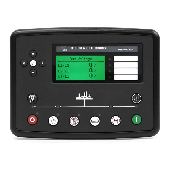
Page 67: Description Of Controls
Description of Controls 4 DESCRIPTION OF CONTROLS CAUTION: The module may instruct an engine start event due to external influences. Therefore, it is possible for the engine to start at any time without warning. Prior to performing any maintenance on the system, it is recommended that steps are taken to remove the battery and isolate supplies. -
Page 68: Control Push Buttons
Description of Controls 4.1 CONTROL PUSH BUTTONS NOTE: For further details, see section entitled Operation elsewhere in this manual. Icon Description Stop / Reset Mode This button places the module into its Stop/Reset Mode . This clears any alarm conditions for which the triggering criteria have been removed. If the generator is running on load and the module is put into Stop/Reset Mode , the module automatically opens the generator bus breaker (‘Close Bus’... - Page 69 Description of Controls NOTE: For further details, see section entitled Operation elsewhere in this manual. Icon Description Auto Mode This button places the module into its Auto Mode . This mode allows the module to control the function of the system automatically. The module monitors various Start Signals and once a start request is made, sends a start request to the DSE8x10 module over the MSC Link.
- Page 70 Description of Controls NOTE: For further details, see section entitled ‘Operation’ elsewhere in this manual. Icon Description Transfer to Mains The Transfer to Mains button control the operation of the mains load switching and is only active in Manual Mode once the generator bus is available.
- Page 71 Description of Controls NOTE: For further details, see section entitled ‘Operation’ elsewhere in this manual. Icon Description Transfer to Generator Bus The Transfer to Generator Bus button control the operation of the mains load switching and is only active in Manual Mode once the generator bus is available.
-
Page 72: Viewing The Instrument
Description of Controls 4.2 VIEWING THE INSTRUMENT PAGES It is possible to scroll to display the different pages of information by repeatedly operating the Next & Previous Page buttons. To view one of the instrument pages towards the end of the list, it may be quicker to scroll left through the pages rather than right! Example... -
Page 73: Status
Configurable Status Screens if configured. For further details of module configuration, refer to DSE Publication: 057-257 DSE8660 MKII Configuration Suite Software Manual. This is the ‘home’ page, the page that is displayed when no other page has been selected, and the page that is automatically displayed after a period of inactivity (LCD Page Timer) of the module control buttons. -
Page 74: Mains
Description of Controls 4.2.2 MAINS Contains electrical values of the mains (utility), measured or derived from the module’s (that controls the mains (utility) switch) voltage and current inputs. Press the Instrumentation Scroll buttons scroll through the Mains parameters. • Mains Voltage (ph-N) •... -
Page 75: Synchroscope Operation
Description of Controls 4.2.2.2 SYNCHROSCOPE OPERATION Note: If the module display is showing the status page when the synchronising process begins, the module automatically switches to the Synchroscope page. The ramp progress will also be displayed on the screen once paralleling has taken place. Initially the synchroscope display shows the difference between the mains and generator bus supplies. -
Page 76: Bus
Description of Controls 4.2.3 BUS Contains electrical values of the bus, measured or derived from the module’s (that controls the generator bus switch) voltage input and MSC link. Press the Instrumentation Scroll buttons scroll through the Bus parameters. • Bus Voltage (ph-N) •... -
Page 77: Commissioning Screens
Description of Controls 4.2.3.1 COMMISSIONING SCREENS NOTE: Some of the items are removed from the commissioning screens if they are not applicable to the module configuration. Commissioning screens are available to both aid the commissioning process and also to give additional information about the synchronising and load sharing process. -
Page 78: Expansion
Description of Controls 4.2.4 EXPANSION NOTE: For further details of module configuration, refer to DSE Publication: 057-257 DSE8660 MKII Configuration Suite Software Manual. Contains measured values from various input expansion modules that are connected to the DSE module. Press the Instrumentation Scroll buttons scroll through the Expansion parameters if configured. -
Page 79: Alarms
Description of Controls 4.2.5 ALARMS When an alarm is active, the Internal Audible Alarm sounds and the Common Alarm LED, if configured, illuminates. The audible alarm is silenced by pressing the Alarm Mute / Lamp Test button. The LCD display jumps from the ‘Information page’ to display the Alarm Page Number of active alarms on Mains Alarms page. -
Page 80: Event Log
Description of Controls 4.2.6 EVENT LOG The module maintains a log of past alarms and/or selected status changes. At the time of writing, the modules log is capable of storing the last 250 log entries. Under default factory settings, the event log is configured to include all possible options; however, this is configurable by the system designer using the DSE Configuration Suite software. -
Page 81: Serial Port
Description of Controls 4.2.7 SERIAL PORT 4.2.7.1 RS232 SERIAL PORT This section is included to give information about the RS232 serial port and external modem (if connected). The items displayed on this page change depending upon configuration of the module. Refer to the system supplier for further details. - Page 82 Description of Controls Connected to an RS232 GSM Modem When the module is powered up, it sends ‘initialisation strings’ to the connected modem. It is important therefore that the modem is already powered, or is powered up at the same time as the module.
- Page 83 Description of Controls Modem Initialisation Sequence The modem attempts to communicate to the module If the Modem and module communicate successfully: In case of communication failure between the modem and module, the modem is automatically reset and initialisation is attempted once more: In the case of a module that is unable to communicate with the modem, the display continuously cycles between ‘Modem Reset’...
- Page 84 Description of Controls Connected to An RS232 MODBUS Master The modules operate as a MODBUS RTU slave device. In a MODBUS system, there is only one Master, typically a PLC, HMI system or PC SCADA system. This master requests for information from the MODBUS slave (The module) and may (in control systems) also send request to change operating modes etc.
-
Page 85: Rs485 Serial Port
Description of Controls 4.2.7.2 RS485 SERIAL PORT This section is included to give information about the currently selected serial port The items displayed on this page change depending upon configuration of the module. Refer to the system supplier for further details. NOTE: Factory Default settings are for the RS485 port to operate at 19200 baud, MODBUS slave address 10. -
Page 86: About
Description of Controls 4.2.8 ABOUT 4.2.8.1 MODULE INFORMATION Contains important information about the module and the firmware versions. This information may be asked for when contacting DSE Technical Support Department for advice. Variant: 86xx MKII About Application Version: The version of the module’s main Variant 8660 MKII firmware file (Updatable using the Firmware Update... -
Page 87: Ethernet
Description of Controls 4.2.8.2 ETHERNET Whilst in the ‘ABOUT’ section, press the Scroll Down button to access more information about the network settings. Network settings change be configured using DSE Configuration Suite Software. The module must be rebooted for the changes to take effect. •... -
Page 88: Data Logging
Description of Controls 4.2.8.3 DATA LOGGING Whilst in the ‘ABOUT’ section, press Scroll Down button to access more information about the data logging settings. Location of logged data. Displays either internal module memory or external USB memory. Data Logging Log to internal memory If data logging is active or inactive Logging active No USB drive present... -
Page 89: User Configurable Indicators
Description of Controls 4.3 USER CONFIGURABLE INDICATORS These LEDs are configured by the user to indicate any one of 100+ different functions based around the following:- Indications - Monitoring of a digital input and indicating associated functioning user’s equipment - Such as Battery Charger On, etc. -
Page 90: Operation
Operation 5 OPERATION NOTE: The following descriptions detail the sequences followed by a module containing the standard ‘factory configuration’. Always refer to your configuration source for the exact sequences and timers observed by any particular module in the field. 5.1 QUICKSTART GUIDE This section provides a quick start guide to the module’s operation. -
Page 91: Stopping The Generator(S)
Operation 5.1.2 STOPPING THE GENERATOR(S) NOTE: For further details, see the section entitled Operation elsewhere in this document. Select Stop/Reset mode. The generator is stopped Page 91 of 146 057-259 ISSUE: 1... -
Page 92: Stop/Reset Mode
Viewing the instruments and event logs is NOT affected by panel lock. NOTE: For further details of module configuration, refer to DSE Publication: 057-257 DSE8660 MKII Configuration Suite Software Manual. Stop/Reset Mode is activated by pressing the Stop/Reset Mode button. -
Page 93: Manual Mode
NOTE: There is no Start Delay in this mode of operation. NOTE: For further details of module configuration, refer to DSE Publication: 057-257 DSE8660 MKII Configuration Suite Software Manual. The starting sequence is controlled in the DSE8x10 module. Page 93 of 146... -
Page 94: Loading Generator Bus
Operation 5.3.2 LOADING GENERATOR BUS Once the generator closes its load switch, the generator bus is seen as available and the generator bus LED illuminates. In Manual Mode , the generator bus load switch is not closed until a ‘loading request’ is made. A loading request can come from a number of sources, synchronising to the Mains if required: •... -
Page 95: Unloading Generator Bus
Operation 5.3.3 UNLOADING GENERATOR BUS Once the generator bus has been placed on load, it is not automatically removed. To manually remove the load either: • Press the Transfer to Mains button • Press the Auto Mode button to return to automatic mode. The module observes all Auto Mode start requests and stopping timers before beginning the Auto Mode Stopping Sequence. -
Page 96: Test Mode
NOTE: There is no Start Delay in this mode of operation. NOTE: For further details of module configuration, refer to DSE Publication: 057-257 DSE8660 MKII Configuration Suite Software Manual. The starting sequence is then controlled in the DSE8x10 module. 057-259 ISSUE: 1... -
Page 97: Loading Generator Bus
, the generator bus load switch is closed automatically when the generator bus is seen as available, synchronising to the Mains if required. Load ramping takes place when appropriate, the DSE8660 MKII controls the generator bus to provide the configured power to the load and or mains supply. -
Page 98: Unloading Generator Bus (From Continuous Parallel)
Operation 5.4.3 UNLOADING GENERATOR BUS (FROM CONTINUOUS PARALLEL) The generator bus load switch is not automatically opened. To manually open the generator bus load switch: • Press the Manual Mode button followed by the Transfer to Mains button • Press the Auto Mode button. -
Page 99: Automatic Mode
Operation 5.5 AUTOMATIC MODE NOTE: If a digital input configured to Panel Lock is active on either module, changing modes on both modules is not possible. Viewing the instruments and event logs is NOT affected by panel lock. Auto Mode is activated by pressing the Auto Mode button. -
Page 100: Generator Bus Available
Operation 5.5.3 GENERATOR BUS AVAILABLE Once the generator closes its load switch, the generator bus is seen as available and the generator bus LED illuminates. In Auto Mode , the generator load switch is closed automatically (if instructed too) when the generator bus is seen as available, synchronising to the Mains if required. -
Page 101: Unloading Generator Bus
Operation 5.5.4 UNLOADING GENERATOR BUS The generator bus load switch is automatically opened. To manually open the generator bus load switch: • Press the Auto Mode button. The module observes all Auto Mode start requests and stopping timers before beginning the Auto Mode Stopping Sequence. •... -
Page 102: Multiple Mains Operation
NOTE: At no time are the generators paralleled with more than one mains supply. Paralleling with mains supplies is always taken in turn. In a multiple mains system, the generator sets are controlled by more than one DSE8660 MKII mains controller and used to provide power to multiple loads. -
Page 103: Dse8660 Mkii Load Ct
Operation 5.6.2 DSE8660 MKII LOAD CT The DSE8660 MKII controller incorporates an optional (but recommended) extra CT measuring the size of the load. Used in conjunction with the CTs measuring the amount of load on the mains supply, this CT allows the 8660 to determine what portion of the load is being supplied by the generators. -
Page 104: Scheduler
Operation 5.7 SCHEDULER The controller contains an inbuilt exercise run scheduler, capable of automatically starting and stopping the set. Up to 16 scheduled start/stop sequences can be configured to repeat on a 7-day or 28-day cycle. Scheduled runs may be island, off load or parallel depending upon module configuration. -
Page 105: Test Mode
Operation 5.7.3 TEST MODE • Scheduled runs do not occur when the module is in Test Mode waiting for a start request. • If a scheduled run configured to ‘Island’ begins when the module is in Manual Mode generator bus is available and in constant parallel, the generator bus is placed in island mode operation. -
Page 106: Msc Compatibility Mode
Description MSC Compatibility NOTE: The DSE5560 and DSE7560 are not compatible with the DSE8660 MKII, only one type of DSExx60 can be connected on the MSC at any time (DSE5560/DSE7560 OR DSE8660 MKII). = The DSE86xx MKII is not be able to communicate with the DSE55xx and DSE75xx series modules on the MSC Link. -
Page 107: Sms Control
Operation 5.9 SMS CONTROL The SMS Control feature (if enabled) allows the user to send control commands to the module via SMS message. There are five control commands that the user is able to send to the module shown in the table below. -
Page 108: Dead Bus Synchronising (Auto Mode)
Synchronising, any number of generators are able to be online and in parallel potentially within 15 seconds, depending upon applications and hardware used. 5.10.2 HARDWARE REQUIREMENTS • DSE8660 MKII controller • DSE8610 MKII controller • DC controlled generator load switch •... -
Page 109: Operation
Operation 5.10.3 OPERATION Before the generator sets are started, their load switches are closed. As there is no AC supply the load switches must be DC controlled. Next, the alternator excitation field is disabled by isolating the supply to the AVRs. The engines are all started at the same time and allowed for the Excitation Delay timer to reach the desired operating speed. -
Page 110: Protections
Protections 6 PROTECTIONS 6.1 ALARMS When an alarm is active, the Internal Audible Alarm sounds and the Common Alarm LED, if configured, illuminates. The audible alarm is silenced by pressing the Alarm Mute / Lamp Test button. The LCD display jumps from the ‘Information page’ to display the Alarm Page Number of active alarms on Mains Alarms page. -
Page 111: Indications
Protections 6.2 INDICATIONS Indications are non-critical and often status conditions. They do not appear on the LCD of the module as a text message. However, an output or LED indicator is configured to draw the operator’s attention to the event. Example •... -
Page 112: Warning Alarms
For further details of module configuration, refer to DSE Publication: 057-257 2130 ID 1 to 4 Analogue Input DSE8660 MKII Configuration Suite PC Software Manual. E to H High The module detected that an analogue input value of a DSE2130 had risen above the Flexible Sensor High Pre-Alarm Trip level. - Page 113 For further details of module configuration, refer to DSE Publication: 057-257 2131 ID 1 to 4 Analogue Input DSE8660 MKII Configuration Suite PC Software Manual. A to J Low The module detected that an analogue input value of a DSE2131 had fallen below the Flexible Sensor Low Pre-Alarm Trip level.
- Page 114 For further details of module configuration, refer to DSE Publication: 057-257 DSE8660 MKII Configuration Suite PC Software Manual. Digital Input A to L The module detected that a digital input configured to create a fault condition became active and the appropriate LCD message is displayed.
- Page 115 Protections Fault Description On start up, If the number of available generators on the MSC link has not achieved the Minimum Number of Sets Not Reached value Minimum Sets Not Reached before the end of the timer, the LCD indicates Minimum Number of Sets Not Reached.
-
Page 116: Electrical Trip Alarms
For further details of module configuration, refer to DSE Publication: 057-257 2130 ID 1 to 4 Analogue Input DSE8660 MKII Configuration Suite PC Software Manual. E to H High The module detected that an analogue input value of a DSE2130 had risen above the Flexible Sensor High Alarm Trip level. - Page 117 For further details of module configuration, refer to DSE Publication: 057-257 2131 ID 1 to 4 Analogue Input DSE8660 MKII Configuration Suite PC Software Manual. A to J High The module detected that an analogue input value of a DSE2131 had risen above the Flexible Sensor High Alarm Trip level.
- Page 118 Protections Fault Description The module detected a bus phase rotation error, an electrical trip is Bus Phase Sequence initiated. The LCD indicates Bus Phase Seq Wrong. The module detected the bus voltage positive sequence had fallen Bus Under Positive Sequence below the configurable Trip level for the configured delay timer.
- Page 119 If the module detects that the mains supply is not sync when the breaker is closed. The LCD indicates Out Of Sync Mains. If the module detects that another DSE8660 MKII shares the same Priority Selection Error priority number, an electrical trip is initiated. The LCD indicates Priority Selection Error.
-
Page 120: Mains Decoupling Alarms
Protections 6.5 MAINS DECOUPLING ALARMS NOTE: These protections only operate only when the mains and generator bus are in parallel, it is disabled at all other times. When the mains (utility) and the generator bus supplies are in parallel, the module monitors for a Mains failure by detecting ROCOF or Vector Shift fault which are set in the module’s configuration. -
Page 121: Front Panel Configuration
Front Panel Configuration 7 FRONT PANEL CONFIGURATION This configuration mode allows the operator to fully configure the module through its display without the use of the DSE Configuration Suite PC Software. Use the module’s facia buttons to traverse the menu and make value changes to the parameters: Next Parameter / Increase Valvue Next... -
Page 122: Main Configuration Edtior
NOTE: More comprehensive module configuration is possible via PC configuration software. For further details of module configuration, refer to DSE Publication: 057- 257 DSE8660 MKII Configuration Suite PC Software Manual. • Ensure the engine is at rest and the module by pressing the Stop/Reset Mode button. -
Page 123: Editing A Parameter
Front Panel Configuration 7.1.3 EDITING A PARAMETER NOTE: Pressing and holding the Menu Navigation buttons provides the auto-repeat functionality. Values can be changed quickly by holding the navigation buttons for a prolonged period of time. • Press the Right or Left buttons to cycle to the section to view/change. -
Page 124: Adjustable Parameters
Front Panel Configuration 7.1.5 ADJUSTABLE PARAMETERS Section Parameter as shown on display Values Display Contrast Language English, Other. Current Date and Time hh:mm Timers LCD Page Timer 0h 0m 0s Scroll Delay 0h 0m 0s Battery Under Voltage Warning Delay 0h 0m 0s Battery Over Voltage Warning Delay 0h 0m 0s... -
Page 125: Running' Configuration Editor
Front Panel Configuration 7.2 ‘RUNNING’ CONFIGURATION EDITOR 7.2.1 ACCESSING THE ‘RUNNING’ CONFIGURATION EDITOR • The Running Editor is enterable whilst the generator is running. All protections remain active when the generator is running while the Running Editor is entered • Press and hold the Tick button to access the Running Editor. -
Page 126: Exiting The 'Running' Configuration Editor
Front Panel Configuration 7.2.4 EXITING THE ‘RUNNING’ CONFIGURATION EDITOR NOTE: The editor automatically exits after 5 minutes of inactivity to ensure security. • Press and hold the Tick button to exit the editor and save the changes. 7.2.5 RUNNING EDITOR PARAMETERS Section Parameter as shown on display Values... -
Page 127: Commissioning
The unit DC supply is fused and connected to the battery and that it is of the correct polarity. Check the operation of the Data Link between the two DSE8660 MKII modules. The Status page displays Module Comms Fail if the Data Link has failed. Ensure one module is configured as the Mains controller and the other as the Bus controller. -
Page 128: Dse 4 Steps To Successful Synchronising
Steps 1, 2, 3 & 4 are to be performed on every DSE8x10 in the system, whereas Steps 2, 3 & 4 are to be performed on every DSE8660 MKII controller. Synchronising and load sharing is often considered to be a complex subject. In fact, it is very simple when broken down into smaller steps. -
Page 129: Control
Commissioning 8.2.1 CONTROL NOTE: Step 1 is only applicable to DSE8x10 controllers. CAUTION!: Failure to perform the Control steps results in poor control over the engine and alternator. This causes long and unstable synchronising as well as unstable kW and kvar load sharing. - Page 130 Commissioning Adjustment of Governor SW2 Increase the setting of the Nominal Frequency by 2.5 Hz (52.5 Hz or 62.5 Hz) Start the generator. With the breaker open the generator will run at setting of SW1 (50 Hz or 60 Hz). 10.
-
Page 131: Determining Connections And Settings For Avrs
Commissioning 8.2.1.2 DETERMINING CONNECTIONS AND SETTINGS FOR AVRS NOTE: Determining the settings of SW1 and SW2 for the AVR MUST only be done once the setup for SW1 and SW2 for the governor has been complete. Changing engine speed affects the level of voltage produced. Setting up the AVR (Adjustment of SW1 and SW2) Before You Start Ensure that the generator is connected to a DEAD BUS BAR WITH NO LOADS connected. - Page 132 Commissioning Adjustment of AVR SW2 Increase the setting of the Nominal Voltage by 10% (230 v to 253 V for example) Start the generator. With the breaker open the generator will run at setting of SW1 (230V for example). 10. Close the generator breaker onto a DEAD BUS BAR WITH NO LOADS connected. The generator voltage shall start to increase towards the new Nominal Voltage setting (253V for example) however it may not achieve this.
-
Page 133: Metering
Commissioning 8.2.2 METERING CAUTION!: Failure to perform the Metering steps results in incorrect power factor and kW calculations leading to problems with kW and kvar load sharing if not corrected. WARNING!: Steps must be taken to ensure that when a CT is open circuit, the system/generator is in a safe state to work around. -
Page 134: Communications
Commissioning 8.2.3 COMMUNICATIONS CAUTION!: Failure to perform the Communications steps results in the controllers being unable to communicate to the other DSE controllers leading to problems during load sharing. NOTE: For further details of module configuration, refer to DSE Publication: 057-238 DSE8610 MKII Configuration Suite PC Software Manual. -
Page 135: Sync Checks
Commissioning 8.2.4 SYNC CHECKS CAUTION!: Failure to perform the Metering steps results in in serious damage to the system (breakers, bus bars, alternators, engines etc) caused by out of sync closures. Check to ensure that all the module’s sensing cables have been connected to the correct phases and that the generator’s load switch has been correctly connected. -
Page 136: Incorrectly Wired Breaker
Commissioning 8.2.4.1 INCORRECTLY WIRED BREAKER When the DSE module’s synchroscope shows the two supplies in sync, if the voltage meter shows a voltage difference the breaker is wired incorrectly. This is shown in the example below. 057-259 ISSUE: 1 Page 136 of 146... -
Page 137: Correctly Wired Breaker
Commissioning 8.2.4.2 CORRECTLY WIRED BREAKER When the DSE module’s synchroscope shows the two supplies in sync, if the voltage meter shows no voltage difference the breaker is wired correctly. This is shown in the example below. Page 137 of 146 057-259 ISSUE: 1... -
Page 138: Fault Finding
Fault Finding 9 FAULT FINDING NOTE: The below fault finding is provided as a guide check-list only. As the module can be configured to provide a wide range of different features, always refer to the source of the module configuration if in doubt. 9.1 STARTING Symptom Possible Remedy... -
Page 139: Instruments
Fault Finding 9.2 INSTRUMENTS Symptom Possible Remedy Check: • That the CT primary, CT secondary and VT ratio settings are correct for the application. • That the CTs are wired correctly with regards to the direction of current flow (p1,p2 and s1,s2) and additionally ensure that CTs are connected to the correct phase (errors occur if CT1 is connected to phase 2). -
Page 140: Communications
Fault Finding 9.4 COMMUNICATIONS Symptom Possible Remedy Check : • RS232 maximum of 15 m is not exceeded • Direct to PC connection requires a Crossover (NULL RS232 connection to PC modem) RS232 cable inoperative • Baud rate of controller and of master device are the same •... -
Page 141: Miscellaneous
Fault Finding 9.5 MISCELLANEOUS Symptom Possible Remedy When editing a configuration using the PC software it is vital that the configuration is first ‘read’ from the controller before editing it. This edited configuration must then be “written” back to the controller for the changes to take effect. -
Page 142: Maintenance, Spares, Repair And Servicing
If you require additional plugs from DSE, please contact our Sales department using the part numbers below. 10.1.1 PACK OF PLUGS Module Type Plug Pack Part Number DSE8660 MKII 007-891 10.1.2 INDIVIDUAL PLUGS Module Terminal Designation Plug Description Part No. -
Page 143: Purchasing Additional Sealing Gasket From Dse
Maintenance, Spares, Repair & Servicing 10.3 PURCHASING ADDITIONAL SEALING GASKET FROM DSE Item Description Part No. Module Silicon Sealing Gasket 020-564 ® 10.4 DSENET EXPANSION MODULES NOTE: A maximum of twenty (20) expansion modules can be connected to the DSE8660 ®... -
Page 144: Warranty
Warranty 11 WARRANTY DSE Provides limited warranty to the equipment purchaser at the point of sale. For full details of any applicable warranty, refer to the original equipment supplier (OEM) 12 DISPOSAL 12.1 WEEE (WASTE ELECTRICAL AND ELECTRONIC EQUIPMENT) If you use electrical and electronic equipment you must store, collect, treat, recycle and dispose of WEEE separately from your other waste 057-259 ISSUE: 1 Page 144 of 146... - Page 145 This Page is Intentionally Blank...
- Page 146 This Page is Intentionally Blank...
Need help?
Do you have a question about the DSE8660 MKII and is the answer not in the manual?
Questions and answers