
Related Manuals for Deep Sea Electronics Plc DSE5520


Summary of Contents for Deep Sea Electronics Plc DSE5520
- Page 1 COMPLEX SOLUTIONS MADE SIMPLE. DEEP SEA ELECTRONICS PLC DSE5520 AUTOMATIC MAINS FAILURE CONTROL MODULE OPERATING MANUAL http://bestgenerator.spb.ru/?page_id=6765...
-
Page 2: Bibliography
Any reference to trademarked product names used within this publication is owned by their respective companies. Deep Sea Electronics Plc reserves the right to change the contents of this document without prior notice. 1 BIBLIOGRAPHY IEEE Std C37.2-1996 IEEE Standard Electrical Power System Device Function Numbers and Contact Designations. -
Page 3: Table Of Contents
DSE Model 5520 Automatic Mains Failure Control and Instrumentation System Operators Manual TABLE OF CONTENTS Section Page BIBLIOGRAPHY ....................2 INTRODUCTION ....................6 CLARIFICATION OF NOTATION USED WITHIN THIS PUBLICATION......7 ICON DESCRIPTIONS ......................7 OPERATION ....................8 CONTROL ..........................8 AUTOMATIC OPERATION .................... - Page 4 DSE Model 5520 Automatic Mains Failure Control and Instrumentation System Operators Manual 9.1.5 PLUG “E” 5 WAY ......................52 9.1.6 PLUG “F” 8 WAY ......................53 9.1.7 PLUG “G” 4 WAY ......................53 9.1.8 PLUG “H” 12 WAY ...................... 53 9.1.9 PC CONFIGURATION INTERFACE CONNECTOR ..........
- Page 5 DSE Model 5520 Automatic Mains Failure Control and Instrumentation System Operators Manual MAINS CT ..........................81 16.6.4 TYPICAL PEAK LOPPING SYSTEM ................82 057-016 5520 OPERATING MANUAL ISSUE 6.1 18/06/07 AM 5 http://bestgenerator.spb.ru/?page_id=6765...
-
Page 6: Introduction
DSE Model 5520 Automatic Mains Failure Control and Instrumentation System Operators Manual 2 INTRODUCTION The DSE 5520 Module has been designed to allow the OEM to meet demand for increased capability within the industry. It has been primarily designed to allow the user to start and stop the generator and if required, transfer the load to the generator either manually or automatically, or in the event of the module detecting a mains failure. -
Page 7: Clarification Of Notation Used Within This Publication
Indicates a procedure or practice which could result in injury to personnel or loss of life if not followed correctly. WARNING! Deep Sea Electronics Plc owns the copyright to this manual, which © cannot be copied, reproduced or disclosed to a third party without prior written permission. -
Page 8: Operation
DSE Model 5520 Automatic Mains Failure Control and Instrumentation System Operators Manual 3 OPERATION 3.1 CONTROL Control of the DSE 5520 module is via push buttons mounted on the front of the module with STOP/RESET, MANUAL, TEST, AUTO, LAMP TEST and ALARM MUTE and START functions. For normal operation, these are the only controls which need to be operated. -
Page 9: Automatic Operation
DSE Model 5520 Automatic Mains Failure Control and Instrumentation System Operators Manual 3.2 AUTOMATIC OPERATION 3.2.1 MAINS FAILURE This mode of operation is used to ensure continuity of supply to critical loads during a mains failure condition. This is the normal mode of operation when installed on a standby generator. NOTE: - If a digital input configured to panel lock is active, changing module modes will not be possible. - Page 10 DSE Model 5520 Automatic Mains Failure Control and Instrumentation System Operators Manual After the starter motor has disengaged, the Safety On timer is activated, allowing Oil Pressure, High Engine Temperature, Under-speed, Charge Fail and any delayed Auxiliary fault inputs to stabilise without triggering the fault.
-
Page 11: Remote Start In Island Mode
DSE Model 5520 Automatic Mains Failure Control and Instrumentation System Operators Manual 3.2.2 REMOTE START IN ISLAND MODE This mode of operation is used to start the set in response to an external start requirement from another device. It may also be used to provide continuity of supply during expected black out events. - Page 12 DSE Model 5520 Automatic Mains Failure Control and Instrumentation System Operators Manual After the starter motor has disengaged, the Safety On timer is activated, allowing Oil Pressure, High Engine Temperature, Under-speed, Charge Fail and any delayed Auxiliary fault inputs to stabilise without triggering the fault.
-
Page 13: Remote Start On Load
DSE Model 5520 Automatic Mains Failure Control and Instrumentation System Operators Manual 3.2.3 REMOTE START ON LOAD This mode of operation is used to start the set in response to rising load levels on the mains supply (if configured). NOTE: - If a digital input configured to panel lock is active, changing module modes will not be possible. - Page 14 DSE Model 5520 Automatic Mains Failure Control and Instrumentation System Operators Manual After the starter motor has disengaged, the Safety On timer is activated, allowing Oil Pressure, High Engine Temperature, Under-speed, Charge Fail and any delayed Auxiliary fault inputs to stabilise without triggering the fault.
-
Page 15: Manual Operation
DSE Model 5520 Automatic Mains Failure Control and Instrumentation System Operators Manual 3.3 MANUAL OPERATION Manual mode is used to allow the operator to control the operation of the generator, and to provide fault finding and diagnostic testing of the various operations normally performed during Automatic mode operation. - Page 16 DSE Model 5520 Automatic Mains Failure Control and Instrumentation System Operators Manual 1. The mains supply fails, 2. A Remote Start on load signal is applied, or an on-load run is configured in the scheduler. 3. The Close Generator button is pressed. If any of the above signals are received, the generator is synchronised and paralleled with the mains supply (if available).
-
Page 17: Test Operation
DSE Model 5520 Automatic Mains Failure Control and Instrumentation System Operators Manual 3.4 TEST OPERATION Test operation is used to perform a full on load test sequence to allow for diagnosis of faults. Alternatively, it may also be used to provide continuity of supply during expected black out events, peak lopping or peak shaving during high tariff periods. - Page 18 DSE Model 5520 Automatic Mains Failure Control and Instrumentation System Operators Manual Once the engine is running, the Warm Up timer, if selected is initiated, allowing the engine to stabilise before accepting the load. After the Warm-up timer has expired then the module will transfer the load from the mains supply to the generator output.
-
Page 19: Protections
DSE Model 5520 Automatic Mains Failure Control and Instrumentation System Operators Manual 4 PROTECTIONS When an alarm is present the Audible Alarm will sound and the Common alarm LED (if configured) will illuminate. The audible alarm can be silenced by pressing the ‘Mute’ button The LCD display will jump from the ‘Information page’... - Page 20 DSE Model 5520 Automatic Mains Failure Control and Instrumentation System Operators Manual Warnings are non-critical alarm conditions and do not affect the operation of the generator system. They draw the operators’ attention to an undesirable condition. In the event of an alarm the LCD will jump to the alarms page and scroll through all active warnings and shutdowns.
- Page 21 DSE Model 5520 Automatic Mains Failure Control and Instrumentation System Operators Manual AUXILIARY INPUTS, auxiliary inputs can be user configured and will display the message as configured in the module. Example Alarm Warning Bearing temp high LOW FUEL LEVEL, will be displayed if the fuel level detected by the fuel level sender falls below the low fuel level setting.
- Page 22 DSE Model 5520 Automatic Mains Failure Control and Instrumentation System Operators Manual Alarm Warning Maintenance Due The following alarms are only applicable if synchronising is enabled: FAILED TO SYNCHRONISE, if the module cannot synchronise within the timer allowed by the Synchronising timer a warning is initiated.
-
Page 23: Analogue Pre-Alarms
DSE Model 5520 Automatic Mains Failure Control and Instrumentation System Operators Manual 4.2 ANALOGUE PRE-ALARMS The following alarms are termed ‘pre-alarms’ as they pre warn the operator of a potentially more serious alarm condition. For instance, if the engine temperature rises past the pre alarm level, a warning condition will occur to notify the operator. - Page 24 DSE Model 5520 Automatic Mains Failure Control and Instrumentation System Operators Manual GENERATOR HIGH FREQUENCY, if the module detects a generator output frequency in excess of the pre-set pre-alarm, a warning is initiated. Alarm Warning High frequency will be displayed, it is an immediate warning.
- Page 25 DSE Model 5520 Automatic Mains Failure Control and Instrumentation System Operators Manual INSUFFICIENT CAPACITY, if the module is configured to limit the import Kw on the mains supply, variations in the load levels will be matched by increasing the Kw on the generator. Should the load level increase to a sufficient demand that the generator is giving 100% of its rating.
-
Page 26: Shutdowns
DSE Model 5520 Automatic Mains Failure Control and Instrumentation System Operators Manual 4.3 SHUTDOWNS Shutdowns are latching and stop the Generator. The alarm must be cleared and the fault removed to reset the module. NOTE:- The alarm condition must be rectified before a reset will take place. If the alarm condition remains it will not be possible to reset the unit (The exception to this is the Low Oil Pressure alarm and similar ‘delayed alarms’, as the oil pressure will be low with the engine at rest). - Page 27 DSE Model 5520 Automatic Mains Failure Control and Instrumentation System Operators Manual OVERSPEED, if the engine speed exceeds the pre-set trip a shutdown is initiated. Alarm Shutdown Overspeed will be displayed. Overspeed is not delayed, it is an immediate shutdown. Alarm Shutdown Overspeed...
- Page 28 DSE Model 5520 Automatic Mains Failure Control and Instrumentation System Operators Manual OIL PRESSURE SENDER OPEN CIRCUIT, if the module detects a loss of signal from the oil pressure sender (open circuit) a shutdown is initiated. Alarm Shutdown Sender Fault will be displayed.
- Page 29 DSE Model 5520 Automatic Mains Failure Control and Instrumentation System Operators Manual CAN ECU FAIL, If the module is configured for CANbus operation and receives a “fail” message from the engine control unit, the engine is shutdown and ‘Can ECU fail” is shown on the module’s display.
-
Page 30: Electrical Trips
DSE Model 5520 Automatic Mains Failure Control and Instrumentation System Operators Manual 4.4 ELECTRICAL TRIPS Electrical trips are latching and stop the Generator but in a controlled manner. On initiation of the electrical trip condition the module will de-energise the ‘Close Generator’ Output to remove the load from the generator. - Page 31 DSE Model 5520 Automatic Mains Failure Control and Instrumentation System Operators Manual MAINS REVERSE POWER, the module will monitor the amount of power being exported to the mains supply. If this is above the setting for the ‘export power level alarm’ then the following will be displayed.
-
Page 32: Rocof / Vector Shift
DSE Model 5520 Automatic Mains Failure Control and Instrumentation System Operators Manual 4.5 ROCOF / VECTOR SHIFT When configured to run in parallel with the mains (utility) supply, the module monitors for ROCOF / Vector shift trips according to the module’s configuration settings. This is included within the module and will detect failure of the mains supply during parallel operation with the generator. -
Page 33: Description Of Controls
DSE Model 5520 Automatic Mains Failure Control and Instrumentation System Operators Manual DESCRIPTION OF CONTROLS The following section details the function and meaning of the various controls on the module. 4.6 TYPICAL LCD DISPLAY SCREENS 4.6.1 TYPICAL STATUS DISPLAY Status Mains available Indicates that the module is in Automatic and that the mains is on load (closed). -
Page 34: Typical Instrument Display
DSE Model 5520 Automatic Mains Failure Control and Instrumentation System Operators Manual 4.6.2 TYPICAL INSTRUMENT DISPLAY Engine oil pressure The display of the engine oil pressure Coolant temperature °C The display of the engine coolant temperature °F Generator Amps The display of all three generator line currents. 4.6.3 TYPICAL ALARM DISPLAY Alarm Warning... -
Page 35: Typical Event Display
DSE Model 5520 Automatic Mains Failure Control and Instrumentation System Operators Manual 4.6.4 TYPICAL EVENT DISPLAY Event log 17 Jan 2005 16:29:49 On the 17 January 2005 at 16:29 the unit detected a mains failure Mains failure condition Event log On the 8 September 2004 at 20:10. -
Page 36: Viewing The Instrument And Event Log
DSE Model 5520 Automatic Mains Failure Control and Instrumentation System Operators Manual 4.6.5 VIEWING THE INSTRUMENT AND EVENT LOG PAGES To view a particular instrument, operate the “Page” button to move to the required page. The LCD will display the page title and then will automatically commence scrolling down the various instruments. -
Page 37: Synchroscope Operation
DSE Model 5520 Automatic Mains Failure Control and Instrumentation System Operators Manual 4.6.6 SYNCHROSCOPE OPERATION (When enabled) Display Detail Initial stage of Synchronising display will only show the difference between the Mains Supply and the V +0.2 Generator Output. Here the display is showing a Hz +2.9 frequency mismatch of +2.9Hz - The genset frequency is too high (indicated by the arrow) and... -
Page 38: Complete Instrumentation List
DSE Model 5520 Automatic Mains Failure Control and Instrumentation System Operators Manual 4.7 COMPLETE INSTRUMENTATION LIST 4.7.1 BASIC INSTRUMENTATION Engine Speed Engine Oil pressure Coolant temperature Fuel level Battery voltage/Charge alt volts Engine run time/Number of starts Next maintenance (if enabled) Generator volts (L1-N, L2-N, L3-N) Generator volts (L1-L2, L2-L3, L3-L1) Generator Hz... -
Page 39: Accessing The Front Panel Configuration Editor
DSE Model 5520 Automatic Mains Failure Control and Instrumentation System Operators Manual 4.8 ACCESSING THE FRONT PANEL CONFIGURATION EDITOR This configuration mode allows the operator limited customising of the way the module operates. Operation Detail To enter the ‘configuration mode’ press both the INFO and STOP buttons together. -
Page 40: Editing Values
DSE Model 5520 Automatic Mains Failure Control and Instrumentation System Operators Manual 4.8.2 EDITING VALUES If the PIN number has not been set, or has been correctly entered : Operation Detail CONFIGURATION The LCD will then display: To view the different configuration functions press the + or - buttons. CONFIGURATION The LCD will then display: Oil Pressure... -
Page 41: List Of Adjustable Parameters (Main Configuration Editor)
DSE Model 5520 Automatic Mains Failure Control and Instrumentation System Operators Manual 4.8.3 LIST OF ADJUSTABLE PARAMETERS (MAIN CONFIGURATION EDITOR) (Factory default settings are shown in bold italicised text) Section Parameter as shown on display Values Oil Pressure Pre Alarm Input settings 0 bar -4bar (1.17bar) Oil Pressure Shutdown... -
Page 42: List Of Adjustable Parameters (Application Editor)
DSE Model 5520 Automatic Mains Failure Control and Instrumentation System Operators Manual 4.8.4 LIST OF ADJUSTABLE PARAMETERS (APPLICATION EDITOR) (Factory default settings are shown in bold italicised text) Section Parameter as shown on display Values ENGLISH , OTHERS Language Display (see note below) Alternative Frequency Enable/Disable... -
Page 43: Display Editor
DSE Model 5520 Automatic Mains Failure Control and Instrumentation System Operators Manual 4.9 DISPLAY EDITOR The Display Editor is user to make changes to display language, contrast and run priority mode. Operation Detail To enter the Display Editor press both the UP and DOWN buttons together. - Page 44 DSE Model 5520 Automatic Mains Failure Control and Instrumentation System Operators Manual CONFIGURATION The LCD will then display: Override starting alarms? Software version x.xx To change the value for the displayed parameter press either the buttons to increase of decrease the value. When “override starting alarms”...
-
Page 45: Led Identification And Front Panel Layout
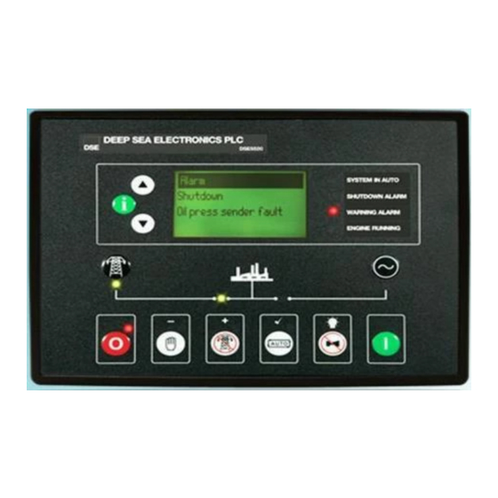
DSE Model 5520 Automatic Mains Failure Control and Instrumentation System Operators Manual 5 LED IDENTIFICATION AND FRONT PANEL LAYOUT 5.1 CONFIGURABLE LED IDENTIFICATION DIAGRAM LED 1 LED 2 LED 3 LED 4 057-016 5520 OPERATING MANUAL ISSUE 6.1 18/06/07 AM 45... -
Page 46: Led Indicators And Logo Insert
DSE Model 5520 Automatic Mains Failure Control and Instrumentation System Operators Manual 6 LED INDICATORS AND LOGO INSERT USER CONFIGURABLE LED’s These LEDs can be configured by the user to indicate any one of 100+ different functions based around the following:- •... -
Page 47: Control Push-Buttons
DSE Model 5520 Automatic Mains Failure Control and Instrumentation System Operators Manual 7 CONTROL PUSH-BUTTONS STOP/RESET This push-button places the module into its Stop/reset mode. This will clear any alarm conditions for which the triggering criteria have been removed. If the engine is running and this push-button is operated, the module will automatically instruct the changeover device to unload the generator (‘Load transfer’... - Page 48 DSE Model 5520 Automatic Mains Failure Control and Instrumentation System Operators Manual TEST This push-button places the module into its ‘Test’ mode. This mode is used to test the function and timing of the generator start and load sequence. The mode is initiated by pressing the ‘Start’ Button and the set will be automatically started and placed on load.
- Page 49 DSE Model 5520 Automatic Mains Failure Control and Instrumentation System Operators Manual TRANSFER TO MAINS This push button is used to control the closure of the mains load switching device and has three modes of operation : 1. Synchronising is NOT enabled. Pressing this button when the generator is running on load and in MANUAL mode, the generator load switch is opened.
-
Page 50: Installation Instructions
DSE Model 5520 Automatic Mains Failure Control and Instrumentation System Operators Manual 8 INSTALLATION INSTRUCTIONS The model DSE 5520 Module has been designed for front panel mounting. Fixing is by 4 clips for easy assembly. 8.1 PANEL CUT-OUT 160.00mm (6.3”) 220.00mm (8.7”) Maximum panel thickness –... -
Page 51: Electrical Connections
DSE Model 5520 Automatic Mains Failure Control and Instrumentation System Operators Manual 9 ELECTRICAL CONNECTIONS Connections to the Module are via plug and sockets. 9.1 CONNECTION DETAILS The following describes the connections and recommended cable sizes to the 8 plugs and sockets on the rear of the Module. -
Page 52: Plug "C" 9 Way
DSE Model 5520 Automatic Mains Failure Control and Instrumentation System Operators Manual 9.1.3 PLUG “C” 9 WAY DESCRIPTION CABLE NOTES SIZE Magnetic pickup screen 0.5mm Connect at module end only! Magnetic pickup 0.5mm Connect to magnetic pickup device Magnetic pickup 0.5mm Connect to magnetic pickup device Electronic Engine ECU... -
Page 53: Plug "F" 8 Way
DSE Model 5520 Automatic Mains Failure Control and Instrumentation System Operators Manual 9.1.6 PLUG “F” 8 WAY DESCRIPTION CABLE NOTES SIZE Mains Loading Relay 2.5mm Connect to mains contactor coil feed supply. Normally Closed Contact Mains Loading Relay 2.5mm Connect to mains contactor coil. Normally Closed Contact Generator Loading Relay 2.5mm... -
Page 54: Pc Configuration Interface Connector
DSE Model 5520 Automatic Mains Failure Control and Instrumentation System Operators Manual 9.1.9 PC CONFIGURATION INTERFACE CONNECTOR 8-way connector allows connection to PC via 810 configuration interface. Module can then be re-configured utilising the 5xxx for Windows™ software. 9.1.10 EXPANSION INTERFACE CONNECTOR 4-way connector allows connection to the 130 input expansion, 157 relay expansion module or 545/548 LED expansion modules. -
Page 55: Connector Function Details
DSE Model 5520 Automatic Mains Failure Control and Instrumentation System Operators Manual 9.2 CONNECTOR FUNCTION DETAILS The following describes the connections and recommended cable sizes to the 8 plugs and sockets on the rear of the Module. 9.2.1 PLUG “A” 8 WAY PIN No DESCRIPTION DC Supply negative. -
Page 56: Plug "C" 9 Way
DSE Model 5520 Automatic Mains Failure Control and Instrumentation System Operators Manual 9.2.3 PLUG “C” 9 WAY DESCRIPTION Magnetic pickup screen Magnetic Input positive. An AC signal from the magnetic pickup positive for speed sensing. Magnetic Input negative. An AC signal from the magnetic pickup negative for speed sensing. -
Page 57: Plug "E" 5 Way
DSE Model 5520 Automatic Mains Failure Control and Instrumentation System Operators Manual 9.2.5 PLUG “E” 5 WAY DESCRIPTION Governor output B. For connection to electronic speed governors for synchronising and load sharing. Governor output A. For connection to electronic speed governors for synchronising and load sharing. -
Page 58: Plug "H" 12 Way
DSE Model 5520 Automatic Mains Failure Control and Instrumentation System Operators Manual 9.2.8 PLUG “H” 12 WAY DESCRIPTION CT Secondary for generator I1 (s2) Used for sensing generator output Current for metering of Amps, KW, KVA and KVAr. CT Secondary for generator I2 (s2) Provides protection for Overcurrent, reverse CT Secondary for generator I3 (s2) power, earth fault and also load sharing. -
Page 59: Engine Control Unit Interface
DSE Model 5520 Automatic Mains Failure Control and Instrumentation System Operators Manual 9.3 ENGINE CONTROL UNIT INTERFACE The module is capable of interfacing with the ECU fitted to electronically injected engines. Different manufacturers engines utilise various different interfaces and protocols. As this is a rapidly developing area we recommend checking with DSE Support as to which engines are currently supported. -
Page 60: Specification
DSE Model 5520 Automatic Mains Failure Control and Instrumentation System Operators Manual 10 SPECIFICATION DC Supply Continuous voltage rating : 8V to 35V Cranking dip protection : Able to survive 0V for 50mS, providing supply was at least 10V before dropout and supply recovers to 5V. - Page 61 DSE Model 5520 Automatic Mains Failure Control and Instrumentation System Operators Manual Dimensions Overall: 240mm x 172 mm x 57mm (9 ½“ x 6 ¾” x 2 ¼”) Panel cut-out: 220mm x 160mm ( 8.7” x 6.3”) Max panel thickness 8mm ( 0.3”) Electrical Safety BS EN 60950 Safety of information technology equipment, including electrical business equipment /Electromagnetic...
-
Page 62: Commissioning
DSE Model 5520 Automatic Mains Failure Control and Instrumentation System Operators Manual 11 COMMISSIONING 11.1.1 PRE-COMMISSIONING Before the system is started, it is recommended that the following checks are made:- 6.1. The module has adequate cooling and all the wiring to the module is of a standard and rating compatible with the system. -
Page 63: Bypassing Alarms At Startup
DSE Model 5520 Automatic Mains Failure Control and Instrumentation System Operators Manual 11.2 BYPASSING ALARMS AT STARTUP When “override starting alarms” is enabled using the Display Editor, it allows alarms to be overridden during the start process by holding the start button. -
Page 64: Fault Finding
DSE Model 5520 Automatic Mains Failure Control and Instrumentation System Operators Manual 12 FAULT FINDING SYMPTOM POSSIBLE REMEDY Unit is inoperative Check the battery and wiring to the unit. Check the DC supply. Check the DC fuse. Unit shuts down Check DC supply voltage is not above 35 Volts or below 9 Volts Check the operating temperature is not above 70 °C. -
Page 65: Typical Wiring Diagram
DSE Model 5520 Automatic Mains Failure Control and Instrumentation System Operators Manual 13 TYPICAL WIRING DIAGRAM NOTE:- When not fitting the ‘neutral CT’, terminal 53 is the CT common and earth. Terminal 52 is not used. 057-016 5520 OPERATING MANUAL ISSUE 6.1 18/06/07 AM 65... -
Page 66: Factory Default Configuration
DSE Model 5520 Automatic Mains Failure Control and Instrumentation System Operators Manual 14 FACTORY DEFAULT CONFIGURATION 057-016 5520 OPERATING MANUAL ISSUE 6.1 18/06/07 AM... - Page 67 DSE Model 5520 Automatic Mains Failure Control and Instrumentation System Operators Manual 057-016 5520 OPERATING MANUAL ISSUE 6.1 18/06/07 AM 67...
- Page 68 DSE Model 5520 Automatic Mains Failure Control and Instrumentation System Operators Manual 057-016 5520 OPERATING MANUAL ISSUE 6.1 18/06/07 AM...
- Page 69 DSE Model 5520 Automatic Mains Failure Control and Instrumentation System Operators Manual 057-016 5520 OPERATING MANUAL ISSUE 6.1 18/06/07 AM 69...
-
Page 70: Sender Wiring Recommendations
DSE Model 5520 Automatic Mains Failure Control and Instrumentation System Operators Manual 15 SENDER WIRING RECOMMENDATIONS 15.1.1 USING EARTH RETURN (SINGLE WIRE) SENDERS. Coolant Fuel level EARTH Pressure temperature NOTE:- . It is important that terminal 60 ( sender common ) is soundly connected to an earth point on the ENGINE BLOCK, not within the control panel and must be a sound electrical connection to the sender bodies. -
Page 71: Using Insulated Return (Two Wire) Senders
DSE Model 5520 Automatic Mains Failure Control and Instrumentation System Operators Manual 15.1.2 USING INSULATED RETURN (TWO WIRE) SENDERS. Fuel Coolant EARTH level Pressure temperature NOTE:- . It is important that terminal 60 (sender common) is soundly connected to an earth point on the ENGINE BLOCK, not within the control panel. -
Page 72: Appendix
DSE Model 5520 Automatic Mains Failure Control and Instrumentation System Operators Manual 16 APPENDIX 16.1 5520 IDMT TRIPPING CURVES (TYPICAL) 16.2 5510 SHORT CIRCUIT TRIPPING CURVES (TYPICAL) 057-016 5520 OPERATING MANUAL ISSUE 6.1 18/06/07 AM... -
Page 73: Accessories
DSE Model 5520 Automatic Mains Failure Control and Instrumentation System Operators Manual 16.3 ACCESSORIES 16.3.1 OUTPUT EXPANSION There are several methods of output expansion available for the 55xx range of modules: - RELAY OUTPUT EXPANSION (157) An expansion module is available, which connects to the configuration socket, and enables the 55xx to use eight additional relays, providing Volt-free contacts for customer connection. -
Page 74: Communications Option
DSE Model 5520 Automatic Mains Failure Control and Instrumentation System Operators Manual 16.4 COMMUNICATIONS OPTION 16.4.1 DESCRIPTION The 5xxx series configuration software allows the 5520 controller to communicate with a PC. The computer can be connected to the module either directly, via a modem (RS232)* or via an RS485 link**. -
Page 75: Rs485 Link To Controller
DSE Model 5520 Automatic Mains Failure Control and Instrumentation System Operators Manual 16.4.4 RS485 LINK TO CONTROLLER The RS485 enabled 5520 modules are able to communicate with a PC or other RS485 enabled device over a standard RS485 connection. Typical uses of RS485 are: •... -
Page 76: Typical Building Management Scheme Using Rs485 Monitoring
NOTE: - The RS485 output uses ‘MODBUS’ protocol. It is possible to use third party software to monitor and control the 5520 module via this protocol. Please refer to Deep Sea Electronics Plc for details. 16.4.5 MODBUS™ The RS485 output uses Modbus™ communications protocol. This uses a master-slave technique to communicate. -
Page 77: Ieee C37.2 Standard Electrical Power System Device Function Numbers
DSE Model 5520 Automatic Mains Failure Control and Instrumentation System Operators Manual 16.5 IEEE C37.2 STANDARD ELECTRICAL POWER SYSTEM DEVICE FUNCTION NUMBERS The DSE 5520 contains many protection devices and functions, which are listed in detail in the following sections. Functions and protections provided corresponding to IEEE C37.2 (1996) system device numbers are listed below. - Page 78 DSE Model 5520 Automatic Mains Failure Control and Instrumentation System Operators Manual A device that is used to close and interrupt an ac power circuit under 52 ac circuit breaker normal conditions or to interrupt this circuit under fault or emergency conditions.
-
Page 79: Enclosure Classifications
DSE Model 5520 Automatic Mains Failure Control and Instrumentation System Operators Manual 16.6 ENCLOSURE CLASSIFICATIONS IP CLASSIFICATIONS BS EN 60529 Degrees of protection provided by enclosures First Digit Second digit Protection against contact and ingress of solid objects Protection against ingress of water No protection No protection Protected against ingress solid objects with a... -
Page 80: Nema Classifications
DSE Model 5520 Automatic Mains Failure Control and Instrumentation System Operators Manual NEMA CLASSIFICATIONS NOTE: - There is no direct equivalence between IP / NEMA ratings. IP figures shown are approximate only. Provides a degree of protection against contact with the enclosure equipment and against a limited amount of falling dirt. -
Page 81: Synchronising Notes
DSE Model 5520 Automatic Mains Failure Control and Instrumentation System Operators Manual 12. SYNCHRONISING NOTES Optionally, the 5520 controller can be configured to synchronise, volts match and parallel with the mains supply. This facility can be used to supply a fixed amount of power to the load and/or mains supply or provide no-break (closed transition) transfers to and from the generator supply. -
Page 82: Http://Bestgenerator.spb.ru/?Page_Id
DSE Model 5520 Automatic Mains Failure Control and Instrumentation System Operators Manual 16.6.4 TYPICAL PEAK LOPPING SYSTEM For further details on this subject, you are referred to the Deep Sea Electronics Guide to Synchronising and Load Sharing Parts 1 and 2. 057-016 5520 OPERATING MANUAL ISSUE 6.1 18/06/07 AM http://bestgenerator.spb.ru/?page_id=6765...
Need help?
Do you have a question about the DSE5520 and is the answer not in the manual?
Questions and answers