Table of Contents
Advertisement
WARNING
Improper installation, adjustment, alteration, service or
maintenance can cause property damage, injury or death.
Read the installation, operating and maintenance
instructions thoroughly before installing or servicing this
equipment.
OWNER
Retain this Manual & ensure available for Service.
Improper installation, adjustment, alteration, service or
maintenance can cause injury, death or property damage.
Read the installation, operation and service instructions
thoroughly before installing or servicing this equipment.
S
E
-T
ERIES
VEN
UBE
Installation, Operation and Service Instructions
INFRARED HEATER
Do not store or use gasoline or other flammable vapors and
liquids in the vicinity of this or any other appliance.
If you smell gas:
Provide Manual to owner upon completion of installation!
Read and thoroughly understand these Instructions before
attempting any installation.
Canada: 563 Barton Street, Stoney Creek, Ontario L8E 5S1
USA: 980 Cobb Place Blvd, NW#100 Kennesaw, GA 30144
www.irenergy.ca
1
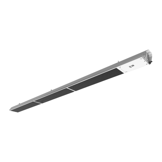
SERIES
Model ETS Infrared Patio Heater
WARNING: FOR OUTDOOR USE ONLY
FOR YOUR SAFETY
1. Open windows
2. Don't touch electrical switches
3. Extinguish any open flame
4. Immediately call your gas supplier
INSTALLER
®
EvenTube
Two-Stage
LT213
10-03-2017
Advertisement
Table of Contents
Troubleshooting

Related Manuals for IR Energy EvenTube ETS


Summary of Contents for IR Energy EvenTube ETS
- Page 1 Installation, Operation and Service Instructions INFRARED HEATER ® SERIES EvenTube Model ETS Infrared Patio Heater Two-Stage WARNING: FOR OUTDOOR USE ONLY WARNING FOR YOUR SAFETY Do not store or use gasoline or other flammable vapors and Improper installation, adjustment, alteration, service or liquids in the vicinity of this or any other appliance.
-
Page 2: Table Of Contents
Table of Contents CAUTION AND GENERAL SAFETY ................................4 AFETY EQUIREMENTS GENERAL ................................. 5 NSTALLATION ODES ............................5 ENERAL NSTALLATION AND ODES ..................................5 UPPLY INES ....................................5 LECTRICAL SPECIFICATIONS : ETS 50 ..............................6 EATER OMPONENTS : ETS 60, 80, 100 ............................. 8 EATER OMPONENTS : ETS 50 .............................. - Page 3 DANGER - CARBON MONOXIDE HAZARD This appliance can produce carbon monoxide which has no odor. Using it in an enclosed space can kill you. Never use this appliance in an enclosed space such as a camper, tent, car or home. WARNING - ELECTRICAL GROUNDING INSTRUCTIONS This heater is equipped with a three-prong (grounding) plug for your protection against shock hazard and should be plugged directly into a properly grounded three-prong receptacle.
-
Page 4: Caution And General Safety
Caution and General Safety CAUTION: FIRE OR BURN INJURY HAZARD At all times maintain clearance to combustible materials as further specified in this manual. Failure to do so can result in serious fire hazard. Never operate heaters in atmosphere containing flammable vapours or combustible dusts. ... -
Page 5: General
General Installation Codes Installations must comply with local building codes, or in their absence, the latest edition of the national regulations and procedures as listed below. General Installation and Gas Codes Heaters must be installed only for use with the type of gas appearing on the rating plate, and the installation must conform to the National Fuel Gas Code, ANSI Z223.1/NFPA 54 in the US and CSA B149.1 Natural Gas &... -
Page 6: Specifications
Specifications Heater Components for ETS 50 5/16 Nut QTY (4) #8-32 x 3/8” Screws 5/16 Lock Washer QTY (55) QTY (4) Gasket QTY (1) Burner Head Grill (with Service Cover) QTY (1) Burner Vent End Cap Hanger Hanger QTY (1) QTY (1) QTY (1) #8 x ½”... - Page 7 Specifications Heater Components for ETS 50 86” Flanged Tube QTY (1) Secondary Reflector QTY (1) Burner Head Reflector QTY (1) 60” Deco Grille QTY (1) Deco Grille Support QTY (1) 30” Deco Grille QTY (1) 42” Baffle QTY (1) 10-03-2017 ERIES...
-
Page 8: Heater Components : Ets 60, 80, 100
Specifications Heater Components for ETS 60, 80, 100 5/16 Nut QTY (4) #8-32 x 3/8” Screws 5/16 Lock Washer QTY (4) QTY (55) Gasket QTY (1) Burner Head Grill (with Service Cover) QTY (1) Burner Middle Vent Hanger Hanger Hanger QTY (1) QTY (1) QTY (1) - Page 9 Specifications Heater Components continued: ETS 60, 80, 100 6’ Baffle 10’ Flanged QTY (1) Tube QTY (1) Primary Reflector QTY (1) 4’ Extension Tube QTY (1) Secondary Reflector QTY (1) Burner Head Reflector QTY (1) Deco-Grille Supports QTY (3) Deco-Grille QTY (3) 10-03-2017 ERIES...
-
Page 10: Dimensional Details : Ets 50
Specifications Dimensional Details: ETS 50 Note: All dimensions are in inches. 10-03-2017 ERIES... -
Page 11: Dimensional Details: Ets 60, 80, 100
Specifications Dimensional Details: ETS 60, 80, 100 Note: All dimensions are in inches. 10-03-2017 ERIES... -
Page 12: Installation Requirements
Installation Requirements Power & Gas Specifications Gas Supply: Rated Input Hi Fire: Low Fire: ETS – 100 100,000 BTU 75,000 BTU ETS – 80 80,000 BTU 60,000 BTU ETS – 60 NG, LP 60,000 BTU 45,000 BTU ETS – 50 50,000 BTU 35,000 BTU Inlet Pressure... -
Page 13: Clearance To Combustibles
Installation Requirements Clearance to Combustibles A general clearance of 18” (0.5 m) in every direction is recommended for servicing around each Burner. This ensures adequate air flow in and around the Heating System. In addition to this it is very important to observe the minimum clearance to combustibles at all times to avoid any possibility of property damage or personal injury. -
Page 14: Heater Mounting
Installation Requirements This heater can be installed Trusses CANNOT be enclosed between wood beams with minimum distances as shown. Wood Beam Air flow MUST NOT be restricted. 1/2" The space above the heater must not be enclosed in order to allow air 1/2"... -
Page 15: Installation / Code Requirements
Installation Requirements Installation / Code Requirements Installation must comply with local building codes and/or, for the USA/National Fuel Gas Code, ANZI Z 223.1 (NFPA 54) and for Canada, CSA B149.1 National Gas and Propane Installation Code (latest editions). Appliance must be electrically grounded in accordance with local codes or, in their absence; the National Electrical Code, ANSI/NFPA 70 in the USA, CSA C22.1 Canadian Electrical Code in Canada. -
Page 16: Installation Instructions
Installation Instructions Installation Sequence: Generally, there is no unique sequence for installation of the burner or heat exchanger. A review of the job site will usually indicate a logical installation order. However, time and expense can be saved if installation is begun at the most critical dimension, watching for interference from overhead beams etc. - Page 17 Installation Instructions Step 2: 10’ Flanged Tube *Face the Tube’s weld-seam downwards, at a 6 o’clock position. Step 3: Burner Hanger 10-03-2017 ERIES...
- Page 18 Installation Instructions Step 4: Middle Hanger Assembly Burner Hanger Step 5: Middle Hanger Burner Hanger 10-03-2017 ERIES...
- Page 19 Installation Instructions Step 6: Coupling Step 7: Torque to 15-25 ft-lbs When installing, orient band-clamp lock bolts to the Extension side at a 3 o’clock or 9 o’clock position to avoid Tube – 4’ contact with reflector. *Face the Tube’s weld-seam downwards, at a 6 o’clock position.
- Page 20 Installation Instructions Step 8: Vent Hanger Step 9: Primary Reflector 10-03-2017 ERIES...
- Page 21 Installation Instructions Step 10: Slide Reflector and Burner Hanger against flange. Step 11: #8-32 x 3/8” screws 10-03-2017 ERIES...
- Page 22 Installation Instructions Step 12: Baffle Bend Baffle tab completely over end of Tube at 6 o’clock position (along the weld seam). Step 13: Vent Terminal #8 x ½” self-drilling screws Slide Vent Terminal over Baffle tab. Secure Vent to Tube using two self-drilling screws.
- Page 23 Installation Instructions Step 14: Secondary Reflector Step 15: #8-32 x 3/8” screws 10-03-2017 ERIES...
- Page 24 Installation Instructions Step 16: Remove Service Cover From Burner Head. Step 17: Burner Head Gasket Note: Ensure Burner Head is properly supported. Use 5/16 washers and nuts to attach burner to flanged tube. 10-03-2017 ERIES...
- Page 25 Installation Instructions Step 18: Slide Burner Head Reflector over Burner Head. Step 19: #8-32 x 3/8” screws 10-03-2017 ERIES...
- Page 26 Installation Instructions Step 20: Attach Grill to Reflector and Burner Head. Step 21: #8-32 x 3/8” screws 10-03-2017 ERIES...
- Page 27 Installation Instructions Step 22: Re-attach Service Door Re-attach Service Cover. (tuck this edge up and in) Step 23: Fasten with acorn nut. 10-03-2017 ERIES...
- Page 28 Installation Instructions Step 24: Before installing the Deco Grilles, bend all the tabs along one long side and both short sides of the Grille for easier fitment. *Gloves recommended! Deco Grille Step 25: 10-03-2017 ERIES...
- Page 29 Installation Instructions Step 26: Deco Grille Step 27: Deco Grille #8-32 x 3/8” screws Install Deco Grille Support first. *Face the tabs of this Support towards the Exhaust! 10-03-2017 ERIES...
- Page 30 Installation Instructions Step 28: You should now have a fully assembled ETS 60/80/100. 10-03-2017 ERIES...
- Page 31 Installation Instructions Installation Sequence ETS 50: Step 1: (ETS 50) Carefully remove the heater from box. Step 2: (ETS 50) Before installing the Deco Grilles, bend all the tabs along one long side and both short sides of the Grille for easier fitment. *Gloves recommended! 30”...
-
Page 32: Installation - Ets 50
Installation Instructions Step 3: (ETS 50) 60” Deco Grille #8-32 x 3/8” screws Install Deco Grille Support first. *Face tabs of this Support towards the exhaust! Step 4: (ETS 50) #8-32 x 3/8” screws End Cap 10-03-2017 ERIES... - Page 33 Installation Instructions You should now have a fully assembled ETS 50. 10-03-2017 ERIES...
-
Page 34: Wiring Diagrams
Wiring Diagrams General Requirements Heaters are normally controlled by line voltage (120V) or low voltage (24V) thermostats. Line voltage thermostats are wired directly while low voltage thermostats use a relay. In all cases, heaters must be grounded in accordance with the National Electric Code, ANSI/NFPA 70 in the US, and the Canadian Electric Code, CSA C22.1 in Canada, and must comply with all local requirements. -
Page 35: External Wiring Options
External Wiring Options Manual Line Switch with Hi-LO wiring diagram Notes: - Using 2 Toggle switchs Hi (on) - Allow Min. contact rating of 1AMP per heater inductive. - Allow 20VA / 24V. transformer Low (On) per heater. Yellow (Hi) Brown (Low) corresponding wires on Patio... -
Page 36: Lighting & Shutdown Instructions
Lighting & Shutdown Instructions Lighting 1. Open manual gas supply valve (ensure gas supply lines have been purged). 2. Turn on switch to energize electric supply. 3. The blower motor will energize. 4. When the motor approaches nominal running RPM, the air-proving switch closes and activates the ignition module. -
Page 37: Maintenance & Trouble Shooting
Maintenance & Trouble Shooting Maintenance For best performance, the certain minimal maintenance procedures should be performed before each heating season: Before performing any services or maintenance, shut off gas and electrical supply to heater. Check condition of forced air blower scroll and motor. Dirt and dust may be blown or vacuumed from the blower. - Page 38 Maintenance & Trouble Shooting Trouble shooting continued… Burner Does Not Light Is spark visible through site glass during ignition trial? If no, further electrical checks by a qualified service person are required. Check to see if gas lines were properly purged of air. ...
-
Page 39: Troubleshooting Chart
Troubleshooting Chart Troubleshooting Chart 10-03-2017 ERIES... -
Page 40: Replacement Parts List
Replacement Parts List Item Part No. Description UG105 Gas Train Assembly for Natural Gas UG106 Gas Train Assembly for Propane CE201 Ignition Module CE202 Wire Harness w/5 pin PLUG to Ignition Module CE011 Blower Motor Assembly w/ 0.26A PSC Motor CE058 Transformer, 115V to 24VAC, 40VA Air Switch w/ Bracket, 0.50”... -
Page 41: Warranty
Warranty SERIES ETS INFRARED HEATERS WARRANTY The manufacturer warrants to the original owner that the product will be free of defects in material and workmanship as described below. Warranty Period Series Component Year Years Years Years Burner & Controls Aluminized Heat Exchanger (Tube) The Manufacturer’s obligation under this warranty is limited to repair or replacement, F.O.B.
Need help?
Do you have a question about the EvenTube ETS and is the answer not in the manual?
Questions and answers