TESTO 310 Instruction Manual
Flue gas analyzer
Hide thumbs
Also See for 310:
- User manual ,
- Instruction manual (36 pages) ,
- Brief instructions (4 pages)
Table of Contents
Advertisement
Advertisement
Table of Contents

Related Manuals for TESTO 310


Summary of Contents for TESTO 310
- Page 1 310 · Flue gas analyzer Instruction manual...
-
Page 3: Table Of Contents
1 Contents Contents Contents ....................3 Safety and the environment ..............5 2.1. About this document ................ 5 2.2. Ensure safety ................... 6 2.3. Protecting the environment .............. 7 Specifications ..................8 3.1. Use ....................8 3.2. Technical data ................. 8 3.2.1. - Page 4 1 Contents Maintaining the product ............... 29 6.1. Cleaning the measuring instrument ..........29 6.2. Cleaning the flue gas probe ............29 6.3. Draining the condensate container ..........29 6.4. Checking / replacing the particle filter ........... 30 Tips and assistance ................31 7.1.
-
Page 5: Safety And The Environment
2 Safety and the environment Safety and the environment 2.1. About this document > Please read this documentation through carefully and familiarize yourself with the product before putting it to use. Pay particular attention to the safety instructions and warning advice in order to prevent injuries and damage to the products. -
Page 6: Ensure Safety
Use only original spare parts from Testo. > Any further or additional work must only be carried out by authorised personnel. Testo will otherwise refuse to accept responsibility for the proper functioning of the measuring instrument after repair and for the validity of certifications. -
Page 7: Protecting The Environment
> Dispose of faulty rechargeable batteries/spent batteries in accordance with the valid legal specifications. > At the end of its useful life, send the product to the separate collection for electric and electronic devices (observe local regulations) or return the product to Testo for disposal. -
Page 8: Specifications
These systems can be adjusted using the testo 310 and checked for compliance with the applicable limit values. The following tasks can also be carried out using the testo 310: • Regulating the O2, CO and CO2 values in combustion plants for the purpose of ensuring optimal operation. -
Page 9: Other Instrument Data
> 8h (pump on, 20°C ambient temperature) battery life EU Directive 2004/108/EC Warranty Measuring instrument, flue gas probe: 24 months Thermocouple: 12 months Sensors O2, CO: 24 months, Rechargeable battery: 12 months Terms of warranty Terms of warranty: see website www.testo.com/warranty... -
Page 10: Product Description
4 Product description Product description 4.1. Measuring instrument 4.1.1. Front view 1 Display 2 Function keys 3 Keypad 4.1.2. Keypad Button Functions Switch measuring instrument on / off [OK] Function key (orange, 3x), relevant function is shown on the display Example [▲] Increase value, select parameter... -
Page 11: Display
4 Product description Button Functions [esc] Back, cancel print process Switch display light on/off Transmit data to the Testo protocol printer. 4.1.3. Display 1 Measurement type (an arrow marks the measurement type that is activated): Icon Measurement Flue gas (icon visible when the instrument is... - Page 12 4 Product description 2 Status: Icon Meaning Measuring gas pump (icon visible when the instrument is switched off) The inner segments light up alternately when the measuring gas pump is running. Error Flashes when an error occurs, an error code is also displayed.
-
Page 13: Connections
4 Product description Icon Possible assignment Right function key: Open configuration menu Switch to the next parameter: 4.1.4. Connections 1 Charging socket for mains unit (Micro USB) 2 Cable to the flue gas probe 3 Gas outlet 4.1.5. Condensate outlet/interface 1 Infrared interface 2 Condensate outlet... -
Page 14: Rear View
4 Product description 4.1.6. Rear view 1 Attachment for carrying strap 2 Condensate trap 3 Magnetic holder 4 Gas outlet 5 Magnetic holder WARNING Magnetic field May be harmful to those with pacemakers. > Keep a minimum distance of 10 cm between pacemaker and instrument. -
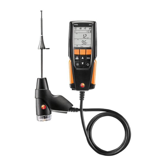
Page 15: Flue Gas Probe
4 Product description 4.2. Flue gas probe 1 Thermocouple 2 Probe shaft 3 Probe handle 4 Connecting cable 5 Removable filter chamber with window, particle filter, and sealing plug for differential pressure measurement 4.3. Area versions The instrument can be configured for 5 area versions. Country- specific calculation formulas, associated measurement parameters and fuels are activated with this setting. - Page 16 4 Product description Area Countries Parameters Fuels version (recom- (ArEA mendation) USA, HU, Line 1: nAt GAS – Natural gas IN, KR O2, T, ProP GAS – Propane P1, P2, FUEL OIL2 – Fuel oil 2 Line 2: Bioh 5 –...
-
Page 17: Reading Display
4 Product description Area Countries Parameters Fuels version (recom- (ArEA mendation) nAt GAS – Natural gas Line1:: O2, T, GPL – Propane uCO, UnI but GAS – Butane Line 2: GAS OIL – Gasoleo A CO, λ, CO2, OIL – Heavy fuel oil Eff gross, T, Wood PELL –... - Page 18 4 Product description Display Measurement parameter Air surplus only when UnI ON Line 1: Measurement period countdown per measuring phase scrolling display/measuring phase display and total measurement period of the UnI measurement display Line 2: Total measurement period of the UnI measurement display Heat of condensation...
-
Page 19: Using The Product
5.1. Mains unit / rechargeable battery The rechargeable battery is permanently installed and can only be changed by a Testo service centre. The measuring instrument is supplied with a partially charged rechargeable battery. > Charge the rechargeable battery fully before using the measuring instrument. -
Page 20: Mains Operation
5 Using the product 5.1.2. Mains operation 1. Connect the plug of the mains unit to the mains unit socket on the measuring instrument. 2. Connect the mains plug of the mains unit to a mains socket. The measuring instrument is powered by the mains unit. If the measuring instrument is switched off, the charging process starts automatically. - Page 21 5 Using the product 3. Make settings: [esc] to revert to the previous parameter at any time. Display / Explanation parameter ArEA (area Selecting the area version activates different version) calculation formulas and associated measurement parameters, see Area versions, page 15. >...
-
Page 22: Measurements Configuration Menu
5 Using the product 5.2.2. Measurements configuration menu This configuration menu enables you to make important settings relating to a measurement. Fuels and measuring units can be set. Press right function key ([set]) after the instrument's initialisation phase. 1. Switch the instrument on: Hold down ], until all segments are shown on the display. -
Page 23: Measuring
5 Using the product 5.3. Measuring 5.3.1. Preparing for measurement 5.3.1.1. Zeroing phases Gas sensors If flue gas measurement ( or ambient CO measurement ( configured, the gas sensors are zeroed when the instrument is switched on (zeroing phase). The flue gas probe must be in the open air during the zeroing phase! Pressure sensor If draught measurement (... -
Page 24: Setting Fuel
5 Using the product Aligning the flue gas probe The flue gas must be able to flow freely past the thermocouple. > Align the probe by turning it as required. The tip of the probe must be in the core current of the flue gas flow. >... -
Page 25: Ambient Co
5 Using the product Carry out measurement (area version 5 with setting To calculate a mean value, a series of measurements is carried out with 3 measuring phases (UnI 1 – UnI 3), each lasting 2 min. and 2 sec. 1. -
Page 26: Draught Measurement
5 Using the product 5.3.4. Draught measurement Do not measure for longer than 5 min, as a drift of the pressure sensor means that the readings could be outside the tolerance limits. Select measurement type > Select → [OK]. Performing the measurement The flue gas probe must be outside the flue. - Page 27 5 Using the product Prepare for measurement 1. Open filter chamber of the flue gas probe: turn it gently anti- clockwise. 2. Remove particle filter (1). 3. Remove the sealing plug (2) in the filter chamber from the holder. 4. Close the gas path with the sealing plug. 5.
- Page 28 5 Using the product CAUTION Hot probe shaft! Risk of burns! > Allow the probe shaft to cool down after a measurement, before touching it! > Only attach the silicone hose to the probe shaft once it has cooled down! 6.
-
Page 29: Maintaining The Product
Mild household cleaning agents and soap suds may be used. Any cleaning of contamination within the probe shaft may only be carried out by Testo Customer Service. 6.3. Draining the condensate container The fill level of the condensate trap can be monitored via the markings on the condensate trap. -
Page 30: Checking / Replacing The Particle Filter
6 Maintaining the product 2. Open the sealing plug of the condensate trap. 3. Let the condensate run out into a sink. 4. Dab off any remaining drops on the condensate outlet with a cloth. 5. Close condensate outlet with sealing plug and press on it firmly. The condensate outlet must be completely closed, other- wise measuring errors could occur if external air gets in. -
Page 31: Tips And Assistance
> Remove the sealing plug and does not shut down. insert the filter. Error message: O2 sensor is worn out > Contact Testo Service Zeroing was carried out in the flue gas duct. > Carry out zeroing in fresh air > Contact Testo Service... - Page 32 > Input/reading in of the company data by Testo Service. For more information, please contact your local dealer or the Testo Customer Service. For contact details, see the back of this document or the website: www.testo.com/service-contact...
-
Page 33: Accessories And Spare Parts
Item no. Mains unit 5V 1A with mini-USB connecting cable 0554 1105 Instrument cleaner (100 ml) 0554 1207 For other accessories and spare parts, please refer to the product catalogues and brochures or look up on the internet at www.testo.com... - Page 34 0970 3100 en 03 V01.00...
Need help?
Do you have a question about the 310 and is the answer not in the manual?
Questions and answers