Table of Contents
Advertisement
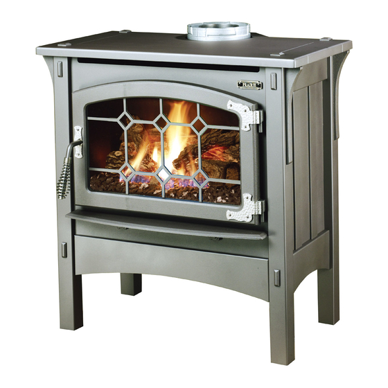
Featuring the
WARNING:
If the information in these instructions is not followed exactly, a fire or explosion
may result causing property damage, personal injury or loss of life.
-
Do not store or use gasoline or other flammable vapors and liquids in the vicinity of this or
any other appliance.
WHAT TO DO IF YOU SMELL GAS
• Do not try to light any appliance.
• Do not touch any electrical switch; do not use any phone in your building.
• Immediately call gas supplier from a neighbor's phone. Follow the gas supplier's instructions.
• If you cannot reach your gas supplier, call the fire department.
-
Installation and service must be performed by a qualified installer, service agency or the gas
supplier.
This appliance may be installed as an OEM installation in a manufactured (mobile) home and
must be installed in accordance with the manufacturer's instructions and the manufactured
home construction and safety standard, Title 24 CFR, Part 3280 or Standard for Installation in
Mobile Homes, CAN/CSA Z240 MH.
This appliance is only for use with the type(s) of gas indicated on the rating plate. A conversion
kit is supplied with the appliance.
Prairie Owner's Manual
Installer:
After installation give this manual to the home-owner
and explain operation of this heater.
Copyright 2007, T.I.
Burner
$10.00
93508115
• Direct Vent Freestanding Stove
• Natural Gas or Propane
• Vent Horizontally or Vertically
• Standard Residential
• Mobile Home Approved
Tested and Listed by
Omni-Test Laboratories, Inc.
Beaverton, Oregon
Report # 028–S–28-5
ANSI Z21.88, CSA 2.33 M9 8, CAN/CGA 2.17-M91
4800 Harbour Pointe Blvd. SW
4050113
Mukilteo, WA 98275
Advertisement
Table of Contents

Related Manuals for Avalon Freestanding Stove


Summary of Contents for Avalon Freestanding Stove
- Page 1 Copyright 2007, T.I. Burner $10.00 93508115 4050113 • Direct Vent Freestanding Stove • Natural Gas or Propane • Vent Horizontally or Vertically • Standard Residential • Mobile Home Approved Tested and Listed by Omni-Test Laboratories, Inc.
-
Page 2: Introduction & Important Information
Introduction and Important Information Introduction We welcome you as a new owner of an Avalon Prairie stove. In purchasing a Prairie you have joined the growing ranks of concerned individuals whose selection of an energy system reflects both a concern for the environment and aesthetics. The Prairie is one of the finest home heaters the world over. -
Page 3: Table Of Contents
Operation Before You Begin ...25 Location of Controls ...25 Starting The Pilot ...26 Starting the Stove for the First Time ...27 Turning the Stove On and Off ...27 Adjusting the Flame Height...27 Adjusting the Blower Speed (optional) ...28 Normal Operating Sounds ...28 Normal Operating Odors ...28... -
Page 4: Safety Precautions
Safety Precautions • IF YOU SMELL GAS: * Do not light any appliance * Extinguish any open flame * Do not touch any electrical switch or plug or unplug anything * Open windows and vacate building * Call gas supplier from neighbor's house, if not reached, call fire •... - Page 5 Safety Precautions • Do not place clothing or other flammable items on or near the heater. Because this heater can be controlled by a thermostat there is a possibility of the heater turning on and igniting any items placed on or near it. •...
-
Page 6: Features & Specifications
This heater is shipped in natural gas (NG) configuration but may be converted to propane (LP) using the included LP conversion kit. The sticker on top of the gas control valve will verify the correct fuel. Travis Industries Installation Options: Freestanding Stove Horizontal or Vertical Vent Residential or Mobile Home Straight or Corner Placement Bedroom Approved The flue collar protrudes 1"... -
Page 7: Installation
Gas-Equipped Recreational Vehicles and Mobile Housing. be installed in Manufactured Housing only after the home is site located. This stove is designed to operate on natural gas or propane (LP). All exhaust gases must be vented outside the structure of the living-area. -
Page 8: Installation Hints
Mobile Home Requirements • When the stove is installed in a mobile home, it must be bolted to the floor and the appliance grounded (use the optional blower with a grounded circuit or other suitable grounding method - current ANSI/NFPA 70 or CSA C22.1). -
Page 9: Heater Placement Requirements
When the stove is installed directly on carpeting, vinyl or other combustible material other than wood flooring or a high pressure laminate wood floor, the stove must be installed on a metal or wood protection panel extending the full width and depth of the heater (Minimum 28”... -
Page 10: Gas Inlet Pressure
Installation Gas Line Installation The gas line must be installed in accordance with all local codes, if any; if not, follow current ANSI Z223.1 or NFPA 54 in the USA and the current CGA B149 in Canada. The heater and gas control valve must be disconnected from the gas supply piping during any pressure testing of that system at test pressures in excess of 1/2 psig (3.45 kPA). -
Page 11: Vent Requirements
Installation Vent Requirements Always maintain the required 1” clearance (air space) to combustible materials to prevent a fire hazard. Do not fill air spaces with insulation. The gas appliance and vent system must be vented directly to the outside of the building, and never be attached to a chimney serving a separate solid fuel or gas-burning appliance. -
Page 12: Approved Vent Configurations
Measuring Vent Lengths Travis Industries (for qualified installers only) To Access the Restrictor Remove the nuts holding the stove top in place (see the illustration Lift the cotter pin out. below). Lift the stove top off the stove. NOTE: The restrictor is shipped in position #1. -
Page 13: Vertical Term. With 0, 2, Or 4 45° Elbows
Installation Approved Venting Configurations for Vertical Terminations with Zero, Two, or Four 45° Elbows • 10’ Minimum System Height (with or without offsets) • 40’ Maximum System Height • 24’ Maximum Offset • The termination must fall within the shaded area shown in the chart. -
Page 14: Hor. Term. With 1 90° Elbow
Installation Approved Venting Configurations with a Horizontal Termination and One 90° Elbow • If using a Snorkel Termination (14” or 36”) add the snorkel height to the vertical height (snorkel terminations are used primarily for basement installations). • The termination must fall within the shaded area shown in the chart. Use the indicated restrictor position. -
Page 15: Hor. Term. With 2 Elbows
Installation Approved Venting Configurations with a Horizontal Termination and Two Elbows ( one 90° vertical and one 90° or 45° horizontal elbow • If using a Snorkel Termination (14” or 36”) add the snorkel height to the vertical height (snorkel terminations are used primarily for basement installations). -
Page 16: Hor. Term. With 3 Elbows
Installation Approved Venting Configurations with a Horizontal Termination and Three 90° Elbows (all vertical) • If using a Snorkel Termination (14” or 36”) add the snorkel height to the vertical height (snorkel terminations are used primarily for basement installations). • The termination must fall within the shaded area shown in the chart. -
Page 17: Vertical Term. With 2 90° Elbows
Installation Approved Venting Configurations for Vertical Terminations with Two 90° Elbows • The termination must fall within the shaded area shown in the chart. Use the indicated restrictor position. 40' (max) 35 feet 30 feet 25 feet 20 feet 15 feet 10' (min) 5 feet 0 feet... -
Page 18: Vertical Term. With 3 Elbows
Installation Approved Venting Configurations for Vertical Terminations with Three 90° Elbows • The termination must fall within the shaded area shown in the chart. Use the indicated restrictor position. 40' (max) 35 feet 30 feet 25 feet 20 feet 15 feet 10' (min) 5 feet 0 feet... -
Page 19: Vent Termination Requirements
Installation Vent Termination Requirements (see illustration below) Venting terminals shall not be recessed into a wall or siding. Minimum 9" clearance from any door or window Minimum 12" above any grade, veranda, porch, deck or balcony Minimum 12" from outside corner walls Minimum 12"... -
Page 20: Finalizing The Installation
Finalizing the Installation Finalizing the Installation Make sure the gas control valve is “OFF” and the heater is cool prior to conducting service. 1 Remove the glass (see page 22) 2 Install the log set and coals (see page 24). We recommend you purge the gas line at this time (with the glass removed). -
Page 21: Air Shutter Adjustment (If Necessary)
Finalizing the Installation If the vent configuration is installed incorrectly the vent may cause the flames inside the heater to lift or “ghost” – a dangerous situation. Inspect the flames after installation to insure proper performance. If the vent configuration is correct, yet the flames are lifting or ghosting, shut off gas to the heater and contact the dealer for information on remedying the problem. -
Page 22: Glass Removal (& Installation)
Make sure the gas control valve is “OFF” and the heater is cool prior to conducting service. Remove the nuts holding the stove top in place (see the illustration below). Lift the stove top off the stove. Unscrew the door handle until it disengages. Swing the door open. - Page 23 Finalizing the Installation Glass Frame Removal and Installation (continued) The spring pin can come loose from the latch assembly. This occurs when it is turned 1/4 turn when it is disengaged. Follow the directions below to re-install the spring pin if it becomes loose. NOTE: The spring pins can be installed with the glass frame in place or...
-
Page 24: Log Installation
Finalizing the Installation Log Installation Make sure the gas control valve is “OFF” and the heater is cool prior to conducting service. Failure to position the parts in accordance with these diagrams or failure to use only parts specifically approved with this appliance may result in property damage or personal injury. NOTE: The burner must be correctly positioned. -
Page 25: Operation
Before You Begin Warning: Read this entire manual before you use your new stove (especially the section "Safety Precautions" on pages 4 & 5). Failure to follow the instructions may result in property damage, bodily injury, or even death. Warning: Do not operate appliance with the glass front removed, cracked or broken. Replacement of the glass should be done by a licensed or qualified service person. -
Page 26: Starting The Pilot
"OFF". However, the pilot will go out if the gas is shut off, the propane tank runs out (or low) or if the stove malfunctions. If the pilot turns off frequently, call your dealer for information. To... -
Page 27: Starting The Stove For The First Time
Adjusting the Flame Height Your stove has an adjustable flame to tailor the look and heat output to your specific needs. It is adjusted by turning the middle dial on the gas control valve. -
Page 28: Adjusting The Blower Speed (Optional)
Adjusting the Blower Speed (optional) The blower helps transfer the heat from the heater into the room. It will not turn on until the heater is up to temperature (approximately 10 minutes after starting). See the illustration below for instructions on adjusting the blower speed. -
Page 29: Maintenance
Painted surfaces should be cleaned with a duster. If scratches occur, lightly sand the area with fine sandpaper. Clean the area and, with the stove cool, apply one or two thin coats of stove paint to the area (mask the area to avoid overspray). -
Page 30: Troubleshooting Table
The pilot light has gone out The gas control valve is turned to "PILOT" or "OFF" ON/OFF switch is turned to "ON" (stove stays on) The remote is too far away from the stove The remote control receiver is turned "Off"... -
Page 31: How This Stove Works
What Turns the Main Burners On and Off This stove uses a millivolt system to control its operation (a millivolt is a very small amount of electricity). The thermopile and thermocouple generate electricity when heated by the pilot flame. This electricity is used to operate the gas valve. -
Page 32: Wiring Diagram
Regulator, Propane Rheostat, Blower w/ Off Position Wiring Harness Travis Industries (for qualified service personnel only) On/Off Switch Brown Black White Molex Green Ground (attached to stove) White Black Brown Blue Blue Part # 93006512 93006514 93006511 93006506 93006507 93006503... -
Page 33: Safety (Listing) Label
The safety (listing) label is on back of the stove. A copy of the safety label is shown below. Report No. 028-S-28-5 Certified for USA & Canada Tested to: ANSI Z21.88b-1999/CSA 2.33-M99 “Vented Gas Fireplace Heater”, CAN/CGA 2.17-M91 “Gas-Fired Appliances for use at High Altitudes”, and UL307b-1995 “Gas Burning Heating Appliances for Manufactured Homes”... -
Page 34: Warranty
Limited 7 Year Warranty To register your TRAVIS INDUSTRIES, INC. 7 Year Warranty, complete the enclosed warranty card and mail it within ten (10) days of the appliance purchase date to: TRAVIS INDUSTRIES, INC., 4800 Harbour Pointe Blvd. SW, Mukilteo, WA 98275. TRAVIS INDUSTRIES, INC. warrants this gas appliance (appliance is defined as the equipment manufactured by Travis Industries, Inc.) to be defect-free in material and workmanship to the original purchaser from the date of purchase as follows: Check with your dealer in advance for any costs to you when arranging a warranty call. -
Page 35: Lp Conversion Instructions
Optional Equipment LP Conversion Instructions Install the conversion kit prior to installing the gas line to ensure proper gas use. Remove the face and glass (see page 22). Remove the log set (if installed - page 24) Remove the burner (see illustration below). Reach into the firebox and lift the burner upwards. - Page 36 Optional Equipment Follow the directions below to remove the natural gas orifice. Apply thread sealant to the LP orifice ( it has ".062" stamped on it) and tighten in place with a 1/2" open end wrench. Replace and secure the mixing tube.
- Page 37 Optional Equipment Remove the pilot orifice following the instructions below. Replace with the propane pilot orifice. The propane conversion kit includes pilot orifice with "35" stamped on it. Replace burner pan. Lift the pilot hood off the pilot assembly. Remove the regulator from the front of the gas control valve.
-
Page 38: Blower
Turn the gas control valve to off and make sure the appliance has fully cooled prior to conducting service. Attach the two black wires at the rear right of the stove to the thermodisk (orientation does not matter). Then slide the thermodisk into the holder underneath the burner pan. - Page 39 Optional Equipment Place the blower near the rear of the stove. Attach the wiring in grommets following the directions below. Route the wires labeled “Valve on/off” and “Solenoid” under the burner pan to a location near the gas control valve.
-
Page 40: Fireback
This allows access to the back of the control box. Phillips Screwdriver Back of Stove Plug the blower in. Let the heater achieve operating temperature and test blower operation. Fireback (Part # 99600220) WARNING: Turn the gas control valve to off and make sure the appliance has fully cooled prior to conducting service. -
Page 41: Installation Addenda
ADDENDUM #1 Class A Chimney Conversion Kit Simpson Duravent provides a conversion kit for those wishing to use an existing wood stove chimney to vent this direct vent stove. The illustration below gives an overview of this type of installation. See the instructions included with the kit for details. -
Page 42: Index
Piping Installation (see Gas Line Install)...10 Restrictor Position ...12 Safety Label...33 Safety Precautions ...4 Starting The Pilot...26 Starting the Stove for the First Time ...27 Thermostat Operation...27 Turning the Stove On and Off...27 Vent Length (see “Vent Config.”)...12 Vent Part Numbers ...11 Vent Requirements ...11...
Need help?
Do you have a question about the Freestanding Stove and is the answer not in the manual?
Questions and answers