Table of Contents
Advertisement
WARNING:
If the information in this manual is not followed exactly, a fire or explosion may result causing
property damage, personal injury or loss of life.
- Do not store or use gasoline or other flammable vapors and liquids in the vicinity of this or any other appliance.
- WHAT TO DO IF YOU SMELL GAS
¥ Do not try to light any appliance.
¥ Do not touch any electrical switch; do not use any phone in your building.
¥ Immediately call gas supplier from a neighborÕs phone. Follow the gas supplierÕs instructions.
¥ If you cannot reach your gas supplier, call the fire department.
- Installation and service must be performed by a qualified installer, service agency or the gas supplier.
10850 117th Place N.E. Kirkland, WA 98033
$10.00
¥
Freestanding Direct Vent
¥
Residential or Mobile Home
¥
Natural Gas or Propane
- - Contact local building or fire
- - Save these instructions
- December, 1999 -
Omni-Test Laboratories, Inc.
93508107
ANSI Z21.88, CSA 2.33 MR 8, CAN/CGA 2.17-M91
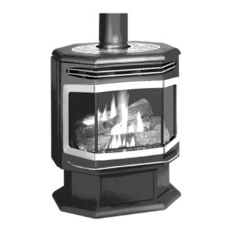
Salish
Gas Stove
officials about restrictions
and installation inspection
requirements in your area.
Tested and Listed by
Beaverton, Oregon
Report # 028 Ð S Ð 19 Ð 1
Advertisement
Table of Contents

Related Manuals for Avalon Salish


Summary of Contents for Avalon Salish
-
Page 1: Introduction
Salish Gas Stove ¥ Freestanding Direct Vent ¥ Residential or Mobile Home ¥ Natural Gas or Propane - - Contact local building or fire officials about restrictions and installation inspection requirements in your area. - - Save these instructions WARNING: If the information in this manual is not followed exactly, a fire or explosion may result causing property damage, personal injury or loss of life. -
Page 2: Safety Precautions
Safety Precautions ¥ IF YOU SMELL GAS: Do not light any appliance Extinguish any open flame Do not touch any electrical switch or plug or unplug anything Open windows and vacate building Call gas supplier from neighborÕs house, if not reached, call fire department ¥... -
Page 3: Safety Precautions
Safety Precautions ¥ Do not place clothing or ¥ Light the heater using the other flammable items on or built-in piezo igniter. Do not near the heater. Because use matches or any other this heater can be controlled external device to light your by a thermostat there is a heater. -
Page 4: Table Of Contents
Table of Contents Introduction Operation Introduction ............1 Safety Notice ............18 Important Information .........1 Location of Controls ...........18 Safety Precautions Starting the Pilot Flame ........19 Starting the Heater for the First Time ......20 Safety Precautions ..........2 Turning the Heater On and Off ......20 Specifications Adjusting the Flame Height........20 Installation Options ..........5... -
Page 5: Specifications
Specifications Installation Options: Features: ¥ Freestanding Stove ¥ Works During Power Outages ¥ Residential or Mobile Home ¥ Realistic ÒWood FireÓ Look ¥ Horizontal or Vertical Vent ¥ Optional Thermostat or Remote Control ¥ Variable-Rate Heat Output ¥ Blower Standard Heating Specifications: Approximate Heating Capacity (in square feet)*..........1,200 to 2,000 Input from Low to High (in BTUÕs per hour) ..........23,000 to 43,000... -
Page 6: Installation
Installation (for qualified installers only) Installation Warnings ! Failure to follow all of the requirements may result in property damage, bodily injury, or even death. ! This heater must be installed by a qualified installer who has gone through a training program for the installation of direct vent gas appliances. -
Page 7: Heater Placement Requirements
Installation (for qualified installers only) Heater Placement Requirements ¥ Heater must be installed on a level surface capable of supporting the heater and vent ¥ Due to the high temperature of the heater, it should be located out of traffic and away from furniture and draperies. -
Page 8: Vent Requirements
Installation (for qualified installers only) Vent Requirements Always maintain the required 1Ó clearance (air space) to combustible materials to prevent a fire hazard. Do not fill air spaces with insulation. The gas appliance and vent system must be vented directly to the outside of the building, and never be attached to a chimney serving a separate solid fuel or gas-burning appliance. -
Page 9: Approved Vent Configurations
Installation (for qualified installers only) Approved Vent Configurations Restrictor Position ¥ A vent restrictor is built into the appliance to The three holes on the control the flow rate of restrictor plate exhaust gases. This correspond to the three ensures proper flames restrictor positions. -
Page 10: Vertical Termõs With (Or Without) 2 45¡ Elbows
Installation (for qualified installers only) Approved Venting Configurations for Vertical Terminations with (or without) Two 45¡ Elbows ¥ 10Õ Minimum System Height (with or without offsets) 35' (max) 35' (max) ¥ 35Õ Maximum System Height ¥ 6Õ Maximum Offset Restrictor Position # 3 30 feet 30 feet... - Page 11 Installation (for qualified installers only) Approved Venting Configurations with a Horizontal Termination ¥ If using a Snorkel Termination (14Ó or 36Ó) add the snorkel height to the vertical height (snorkel terminations are used primarily for basement installations). ¥ The termination must fall within the shaded area shown in the chart. Use restrictor position #1. Natural Gas (NG) Installations NOTE:...
-
Page 12: Vertical Termõs With Two 90¡ Elbows
Installation (for qualified installers only) Approved Venting Configurations for Vertical Terminations with Two 90¡ Elbows ¥ The termination must fall within the shaded area shown in the chart. Use the indicated restrictor position. 35' (max) 35' (max) Restrictor Position # 3 30 feet 30 feet Restrictor... -
Page 13: Termination Requirements
Installation (for qualified installers only) Termination Requirements (see the illustration below) Minimum 9" clearance from any door or window Roof Minimum 12" above any grade, veranda, porch, deck or balcony Surface Minimum 12" from outside corner walls 11Ó Min. Minimum 12" from inside corner walls Roof 6Ó... -
Page 14: Finalizing The Installation
Installation (for qualified installers only) Finalizing the Installation Turn the gas control valve to ÒOFFÓ prior to conducting any service. Open the door (see page 16). Install the log set and coals (see page 17). We recommend you purge the gas line at this time (with the door open). This allows gas to be detected once it enters the firebox, ensuring gas does not build up. - Page 15 Installation (for qualified installers only) Let the heater burn for fifteen minutes. Adjust the air shutter, if necessary, to achieve the correct looking flame (see the illustration below). Loosen this screw two turns. ¥ The air shutter adjusts the amount of air that mixes with the gas before it exits the burner holes.
-
Page 16: Opening The Door
Installation (for qualified installers only) Opening the Door Swing the left panel back. Open both the top and bottom latch. Strike With the pawl free of the strike, the door may be swung open. Pawl Door Frame When securing the door, make sure the pawl fits over the strike before tightening. -
Page 17: Log Set And Coal Installation
Installation (for qualified installers only) Log Set and Coal Installation Preparing the Glowing Embers: The glowing embers come in a single strip. Stretch them as thin as possible (nearly transparent) to form three strips of the following sizes: One Strip Approximately 7-1/2Ó... -
Page 18: Operation
Operation Safety Notice Read this entire manual (especially the ÒSafety PrecautionsÓ on pages 2 and 3) before using this stove. Failure to follow the instructions may result in property damage, bodily injury, or even death. Location of Controls ON/OFF Switch The on/off switch is located on the back of the heater. -
Page 19: Starting The Pilot Flame
Operation Starting The Pilot Flame The pilot flame is required to ignite the main burners (it also plays a safety role). It should be left on once lit. It will stay lit unless the gas control valve is turned to "OFF". However, the pilot will go out if the gas is shut off, the propane tank runs out (or low) or if the stove malfunctions. -
Page 20: Starting The Heater For The First Time
Operation Starting the Heater for the First Time Cleaning Gold Surfaces Fingerprints or other marks left on gold surfaces may become etched in place if they are not wiped clean prior to turning the stove on. With the heater cool, clean gold surfaces with denatured alcohol and a soft cloth. -
Page 21: Adjusting The Blower Speed
Operation Adjusting the Blower Speed The blower helps transfer the heat from the heater into the room. It will not turn on until the heater is up to temperature (approximately 10 minutes after starting). See the illustration below for instructions on adjusting the blower speed. -
Page 22: Maintenance
Maintenance Cleaning Your Heater Warning Fingerprints or other marks left on the optional gold surface may become etched in place if they are not wiped clean prior to turning the stove on. With the heater cool, use denatured alcohol and a soft cloth to clean gold surfaces. Other cleaners may leave a film that may become etched into the gold. -
Page 23: Troubleshooting Steps
Maintenance Start the pilot and turn on the main burner. The flames should be orange/yellow and not touch the top of the firebox. If the pilot or main burners do not burn correctly, contact your dealer for service. Monitor the blower operation. Remove any debris or vegetation near the vent termination. -
Page 24: How This Heater Works
Maintenance How this Heater Works Warning This heater was designed with safety as the primary concern. Many of the components inside this heater are for safety purposes. Therefore, only certified gas service technicians should service this heater. What Turns the Main Burners On and Off This heater uses a millivolt system to control its operation (a millivolt is a very small amount of electricity). -
Page 25: Wiring Diagram
Maintenance Wiring Diagram Thermopile Piezo Igniter Orange Gas Control Valve Thermocouple Brown White terminal Copper Co-Axial Wire Jumper Wire Green On/Off (Manual Switch Operation) Chassis Blower Ground Green Motor Black White 120 Volt Black Grounded A.C. Power Supply Black Optional Remote Optional White... -
Page 26: Safety Label
Safety Label The listing label is shown below for your records. It can be found on the back panel. Salish DVL Stove Listed Gas-Fired Vented Fireplace Heater Report No. 028-S-22-05 February, 1999 Tested and certified by OMNI-Test Laboratories, Inc. to the combustion performance and construction requirements of ANSI Z21.88/CSA 2.33-1998, applicable sections of UL 307b and CAN/CGA 2.17-M91. -
Page 27: Warranty
Warranty To register your TRAVIS INDUSTRIES, INC. 7 Year Warranty, complete the enclosed warranty card and mail it within ten (10) days of the appliance purchase date to: TRAVIS INDUSTRIES, INC., 10850 117th Place N.E., Kirkland, Washington 98033. TRAVIS INDUSTRIES, INC. warrants this gas appliance (appliance is defined as the equipment manufactured by Travis Industries, Inc.) to be defect-free in material and workmanship to the original purchaser from the date of purchase as follows: Years 1 &... -
Page 28: Optional Equipment & Addenda
Optional Equipment LP Conversion Instructions (for qualified technicians only) Install the conversion kit prior to installing the gas line to ensure proper gas use. Open the door (see page 16). Remove the logs, ember strips, and kibbles (if installed - page 17) Remove the burner (see illustration below). - Page 29 Optional Equipment Follow the directions below to remove the natural gas orifice. Apply thread sealant to the LP orifice (#48 - it has "48" stamped on it) and tighten in place with a 1/2" open end wrench. Slide the adjustable shutter back in place over the orifice. Loosen the air shutter Rotate the air control shutter control (see page 15).
- Page 30 Optional Equipment Install the logs and embers. Shut the door. Remove the regulator from the front of the gas control valve. Replace with the propane regulator, using the new gasket and screws included with the regulator. NOTE: Leak test this area after the heater is installed, gas is connected, and the main burner is lit.
-
Page 31: Thermostat
Optional Equipment Thermostat (Part # 99300650) Do not connect 120 VAC to the gas control valve or wiring of this unit. Route the thermostat wire through the back of the right side panel (there is a hole beneath the on/off switch) and attach to the on/off switch (see the illustration below). -
Page 32: Remote Thermostat
Optional Equipment Remote Thermostat (part # 99300653) Do not connect 110-120 VAC to the gas control valve or wiring system of this unit. ¥ Follow the instructions included with the remote thermostat for installation. Using the Remote Thermostat The remote thermostat has a 1 to 2 minute lag time between the time the thermostat is turned up and the heater turns on. -
Page 33: Gold Trivet
Optional Equipment Gold Trivet (part # 93005045) N O T E : The vent must be detached before installing the trivet Ð install this component before installing the vent. Follow the directions below to install the optional gold trivet. Open both side doors. Remove the four screws holding the cast top assembly in place. -
Page 34: Installation Addenda
Installation Addenda ADDENDUM #1 Class A Chimney Conversion Kit Simpson Duravent provides a conversion kit for those wishing to use an existing wood stove chimney to vent this direct vent stove. The illustration below gives an overview of this type of installation. See the instructions included with the kit for details. -
Page 35: Interior Masonry Chimney Conversions
Installation Addenda ADDENDUM #2 Interior Masonry Chimney Conversions ¥ Follow the requirements and use the equipment listed in the illustration to the right to install this appliance into an interior masonry chimney. ¥ Maximum vertical rise is 30' ¥ Minimum vertical rise is 10' ¥... -
Page 36: Index
Index Adjusting the Blower Speed......21 Lifting Flames ..........15 Adjusting the Flame Height ......20 Listing Label (Safety Label) ......26 AFUE............5 Log Installation ...........17 Air Shutter Adjustment........15 Maintaining Your StoveÕs Appearance ..22 Alcoves (see ÒHeater Placement Req.Ó) ..7 Natural Gas Verses Propane......2 Altitude Considerations.......8 On/Off Operation........20 Amperage (of blower)........5...
Need help?
Do you have a question about the Salish and is the answer not in the manual?
Questions and answers